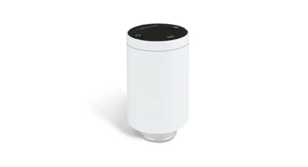
![]() Wireless, thermostatic TRV head
Wireless, thermostatic TRV head
Manual for models: TRV10RFM, TRV10RAM i TRV28RFM
Quick Guide
DISTRIBUTOR OF SALUS CONTROLS:
QL CONTROLS Sp. z o.o., Sp. k.
Rona 4,
43-262 Kobielice,
Poland
Importer:
SALUS Controls Plc
Units 8-10 Northfield Business Park
Forge Way, Parkgate, Rotherham
S60 1SD, United Kingdom

www.salus-controls.eu
SALUS Controls is a member of the Computime Group Maintaining a policy of continuous product development SALUS Controls plc reserves the right to change specification, design and materials of products listed in this brochure without prior notice.

Introduction
The TRV thermostatic head is controlled through wireless ZigBee communication protocol. It can replace a classic, manual thermostatic head in a very quick and easy way. For proper operation of the TRV head it is necessary to synchronize it correctly with a wireless thermostat using the CO10RF coordinator or UGE600 Internet gateway (all devices are sold separately). TRV head paired with the iT600RF series digital thermostats (e.g. VS10RF / VS20RF / HTRS-RF (30) / HTRP-RF (50) / TS600) provides comfort within the whole room, not just in the radiator area.
Product Compliance
This product complies with the essential requirements and other relevant provisions of Directives 2014/53/EU, 2014/30/EU, 2011/65/EU. The full text of the EU Declaration of Conformity is available at the following internet address: www.saluslegal.com.
 Safety Information
Use in accordance to national and EU regulations. Use the device as intended, keeping it in dry condition. Product for indoor use only. Installation must be carried out by a qualified person in accordance to national and EU regulations.
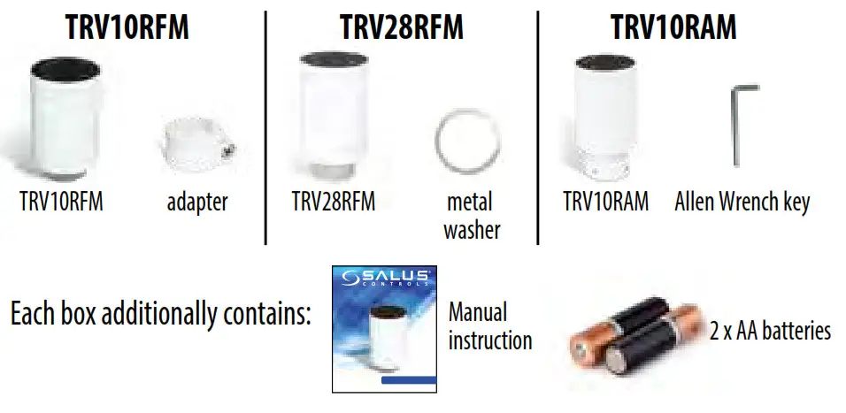
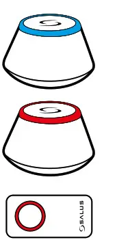
Box Content
General information
The TRV head is a modulating device. This means that the valve can be gradually closed or opened, depending on the current room temperature measured by a thermostat and the setpoint temperature.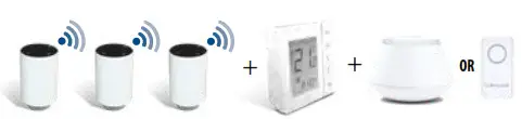
Note: One thermostat can control up to 6 TRV heads within one room. To achieve the best possible results in cooperation between the thermostat and the heating source, it is recommended to use the RX10RF receiver. RX10RF turns on the heat source depending on the demand signal sent by a thermostat. More information about the RX10RF receiver is included in its user manual.
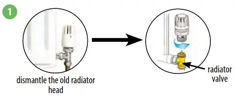
Checking compatibility with the heating system
- TRV head is compatible with most of the thermostatic valves available on the market, however, before installation, please check whether the valve is suitable for use with the TRV head.

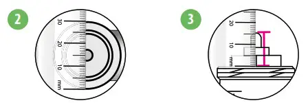
Note: If all valve dimensions are consistent with those given below, then the TRV head will be compatible. If there are dimension differences, contact us or the installer to find a replacement for the valve. - Measure the thread diameter. Thread for the TRV10RFM must have a diameter of 30 mm, and for the TRV28RFM – 28 mm.

- Measure the height of the valve’s pin when it is in the open position. For TRV10RFM valve’s pin height should be 13-15 mm, while for TRV28RFM 10-11 mm.
TRV28RFM head installation
For MMA or Herz M28x1,5 thermostatic valves make sure you have a metal washer as shown in the picture.
NOTE: For the Comap valve with M28 thread you do not need to mount a metal washer.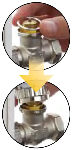
TRV10RFM head installation
For a standard thermostatic valve with M30x1,5 thread (e.g. Oventrop, Honeywell, TA, Heimeier) TRV10RFM head installation looks like as shown in the picture.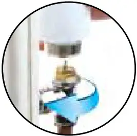
TRV head installation on the Danfoss RA valve
When mounting the TRV10RFM head on the Danfoss RA valve (see picture), please use the RA adapter included with the head. However, to install the TRV10RAM head it is necessary to use the Allen Wrench key.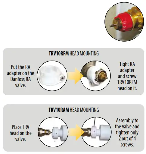
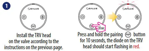
TRV head setup
- Remove the battery cover located on the side of the device.

- Insert the batteries according to the markings and close the battery cover.
- The LED will start blinking green/red informing about the software version.

- When the LED diode lights up continuously with a red color, screw the TRV on the valve.
- Press any button to start the adaptation process of TRV head with a thermostatic valve. The process takes up to 5 minutes.

- When the LED goes out and the TRV head does not make any sounds, the adaptation process is finished. Equipment is ready for pairing with the thermostat.


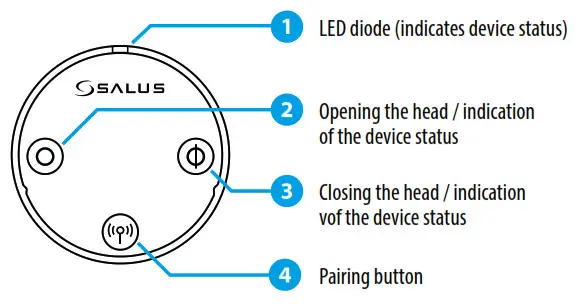
User interface
Note: Buttons lock themselves automatically after 5 minutes from the last one keystroke.
| To do this… | Press the… |
| …pair with thermostat | …pairing button |
| …lock/unkxk the buttons | …pairing |
| …manually open the valve | …opening button Ø for 5 seconds. |
| …manually close the valve | …closing button |
| …enter the automatic mode | …shortly pairing button st I |
| …remove the head from the ZigBee network | …pairing button |
| …restore factory default settings | …Open O, pairing |
Choose the type of coordinator for ZigBee network
Choose one type of ZigBee network coordinator and prepare it for work with iT600 series devices:
- Online – the system is connected to the Internet via an Internet gateway UGE600 or
- Offline – with an option of connecting the system to the Internet using a gateway UGE600 or
- Offline – by using CO10RF coordinator – no possible to connect system to the Internet

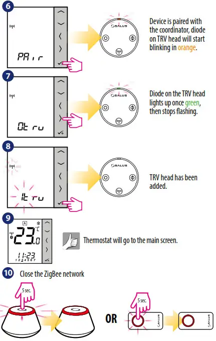
Thermostat pairing with the TRV head in Online mode
 WARNING! You can connect up to 6 TRV heads to one regulator.
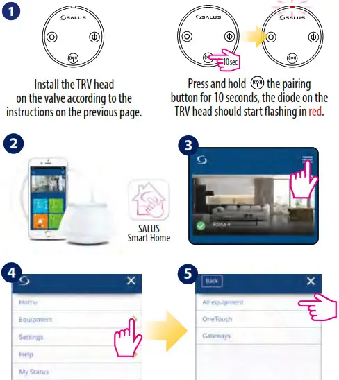
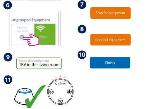
LED diode on TRV head flashes in orange. Now TRV head need to be paired with a thermostat.
NOTE: TRV head and thermostat must be in the same heating zone! 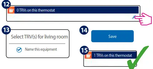
Thermostat pairing with the TRV head in Offline mode
WARNING! You can connect up to 6 TRV heads to one regulator.
 Note: The following example shows the pairing process with the VS10/20..RF thermostat. For HTRS-RF(30) and HTRP-RF(50) thermostats, the pairing process shall be done in the same way.
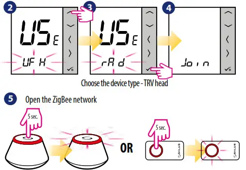
LED diode indications
| When… | TRY Status | LED diode… | Valve |
| …power supplied | TRV head indicates the software version | …alternately flashes red / green indicating the software version. A more detailed description is in ; IRV head setup” section on the previous page. | |
| …TRV head adapts to the valve | … flashes in green, then red and it switches off when the adaptation process has been done. When the LED will continue to flash red it means that the adaptation process failed. | ||
| …TRV head has been added to the network. | … flashes in orange (has been added to the network). TRV head should be paired now with the thermostat. | dosed | |
| .. TRV head is added to the network, but it is not paired with a thermostat | Auto mode | …flashes in orange | closed |
| TRV head is open in manual mode | …flashes twice in green when pressing the opening or closing button. | 100% open | |
| TRV head is closed in manual mode | …flashes once in green after a short press of the opening or closing button. | closed | |
| … TRV head is in normal operating mode | Auto mode | …flashes once in green after a short press of the opening or dosing button. | open in range from 1% up to 100% |
| Auto mode | …flashes once in red after short press of the opening or closing button. | closed | |
| TRV head is open in manual mode | ….flashes twice in green after short press of the opening or closing button. | 100% open | |
| TRV head is closed in manual mode | …flashes twice in red after short press of the opening or closing button. | closed | |
| The Window Open function is active | …flashes in green and red 2 times every 10 seconds. | closed | |
| …TRV head is paired with the thermostat. | Auto mode | …does not light up. |
| …TRV head is removed from the network. | …flashes once in orange (TRV head is removed from the coordinator’s memory) and then flashes in red. | ||
| …identification of the TRV head is tumed on | …flashes in green for a maximum of 10 minutes. | ||
| … wireless communication with the TRV head is lost | Auto mode | _flashing alternately in green and red after a short press of the opening or dosing button. | |
| TRV head is open in manual mode | …flashes twice in green after a short press of the opening or closing button. | 100% open | |
| TRV head is closed in manual mode | …flashes twice in red after a short press of the opening or closing button.. | dosed | |
| …when battery power is too low | _flashesthreetimes in red every 10 seconds (or less often if the batteries in the TRV head are very weak). | 25% open | |
| …an error occurred during TRV head assembly | … flashes alternately in red and green. |
Additional functions:
Frost protection mode
When the valve is manually closed, the TRV head automatically activates frost protection mode. The setpoint temperature of the frost protection mode is set on the thermostat. This function is activated when the room temperature drops below the frost protection setpoint temperature set on the thermostat. TRV head automatically maintains setpoint temperature if there is communication between TRV head and thermostat.
Open window function
TRV head checks the speed of temperature drop in the room. If the temperature drop is fast, it is assumed that in the room has been opened window. The function is active when the TRV head communicates with the thermostat, is in automatic mode and the batteries are not discharged.
Protection against scale deposits
Do not leave the valve open for a long time because it can cause scale deposits on it. TRV head has a protection function against scale deposits. It starts to opening automatically once every 14 days if no valve movement is detected. Protection will also work no matter if TRV head is in auto mode or manual mode
Manual mode
To open or close the TRV head in manual mode, follow the procedure described below. If the steps described below do not bring any results it means that probably the TRV head buttons are locked and they should be unlocked first.
To open the valve manually, press and hold the opening button. The green LED diode flashes once and the TRV head will start to open the valve. 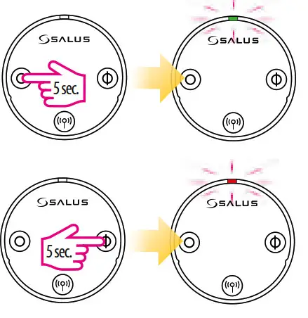 To close the valve manually, press and hold the closing button. The red LED diode flashes once and the TRV head will start closing the valve.
Note: To exit the manual mode and go back to auto mode – press once the pairing button (antenna). The red LED diode will flash once, indicating return to auto mode.
Technical Information
| Model | TRV10RFM / TRV28RFM / TRV10RAM |
| Type | Wireless, thermostatic TRV head M30 x 1.5 / M28 x 1.5 |
| LED signaling | Tri-color LED (red/green/orange) |
| Adaptation with a valve | Automatic |
| Power supply | 2 x AA batteries |
| Control method | Modulation |
| Communication | Wireless, ZigBee 2.4 GHz |
| Operating temperature | 0 to 45°C |
| Storage temperature | -20 to 60°C |
| Ambient humidity | 5 to 95% RH |
| IP protection level | IP30 |
| Dimensions [mm] | H=88.6, Ø=51 |
Warranty
SALUS Controls warrants that this product will be free from any defect in materials or workmanship, and shall perform in accordance with its specification, for a period of two years from the date of installation. SALUS Controls sole liability for breach of this warranty will be (at its option) to repair or replace the defective product.
Customer Name: ……………………………………………………………………….
Customer Address: …………………………………………………
Post Code:………………………………………………………………………………………..
Tel No: ……………………………………………………………………………………………….
Email: ………………………………………………………………………………………………..
Engineers Company: …………………………………………………………………………….
Tel No: ……………………………………………………………………………………………….
Email: ………………………………………………………………………………………………..
Installation Date: ………………………………………………………………………………….
Engineers Name: ………………………………………………………………………
Engineers Signature: …………………………………………………………………………….


 Thermostat User Guide")
 Wireless Digital Thermostat User Manual")


 Wireless Digital Thermostat User Manual")

 Wireless Digital Thermostat User Manual")


 Wireless Room Thermostat User Guide")