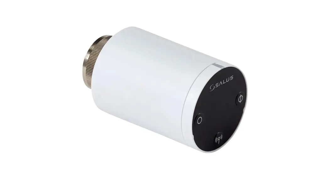
![]() TRV10RFM Smart Radiator Control
TRV10RFM Smart Radiator Control
User Guide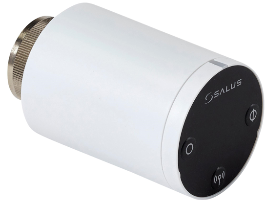 Wireless Radiator Controller
Model: TRV10RFM
INSTRUCTION MANUAL
TRV10RFM Smart Radiator Control User Guide
Contents of the box
Icons used in this manual: Safety
![]() Important info
Important info
Box Contents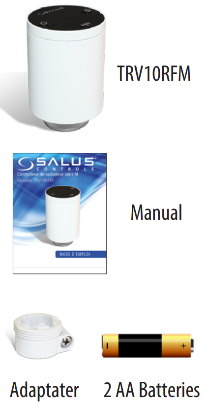 For the latest PFD Instruction Manual, go to www.salus-controls.com
System Overview
To achieve the best control from the unit and thermostat, we recommend they are used with the SALUS system receiver configured to RX1. The system receiver will turn the boiler on or off when requested by the thermostat. See your boiler receiver manual for more information about the RX1 configuration.![]() The unit is modulating, which means it opens or closes partially or 100% depending on the relationship between the actual room temperature and the required room temperature measured by the VS10/20RF.
The unit is modulating, which means it opens or closes partially or 100% depending on the relationship between the actual room temperature and the required room temperature measured by the VS10/20RF.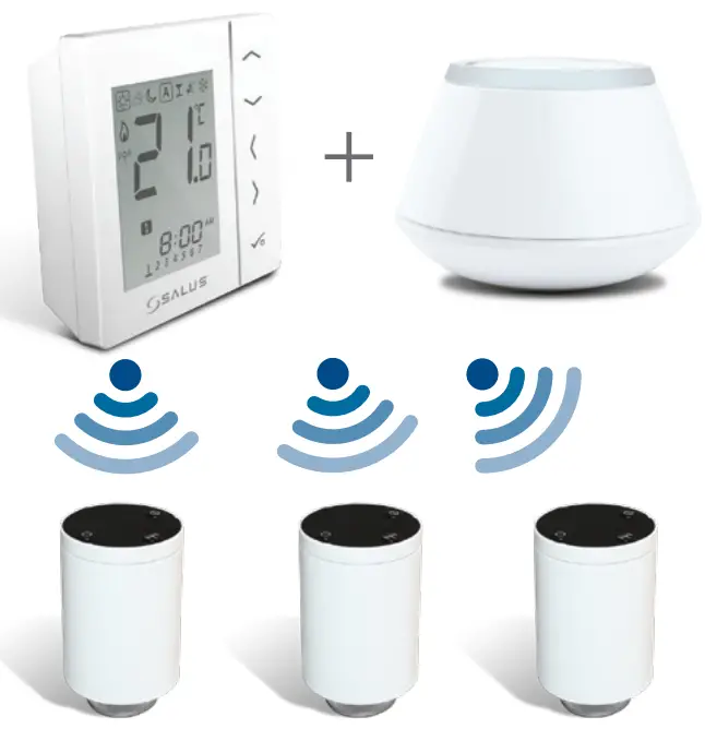
![]() Up to 6 units can be connected to a VS10RF/VS20RF.
Up to 6 units can be connected to a VS10RF/VS20RF.
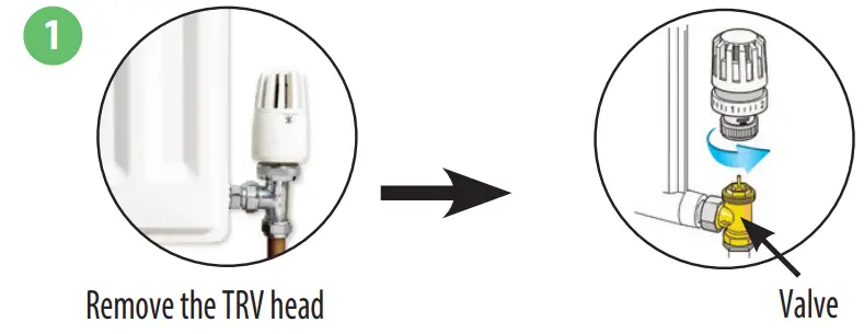
Checking the compatibility of your heating system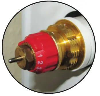 If you can not see any thread on the valve and it looks like this picture, you may be able to use the RA adapter supplied.
TRV10 fits 30×1,5 mm thread.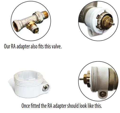
Preparing to Pair the Unit
- Press and hold the button on the Universal Gateway for five seconds. This puts the Universal Gateway in pairing mode. See your Universal Gateway manual for more information.

- Ensure the wireless thermostat is powered up and ready for pairing. See your thermostat manual for more information.
- If you are using the optional RX10RF wireless boiler receiver configured for remote boiler switching, ensure this has been powered up and the red LED has gone from flashing to steady. See your boiler receiver manual for more information.
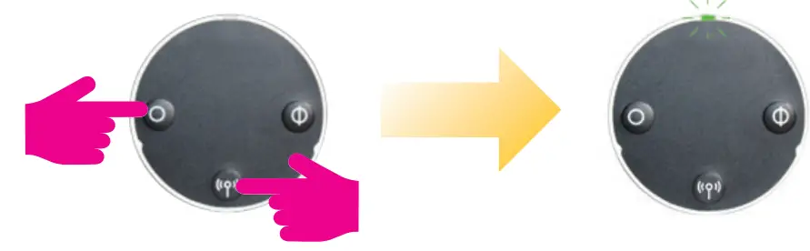
Pairing the Unit
Press and hold the pairing button for 10 seconds. You can pair up to 6 units with one thermostat. Pair the units room by room.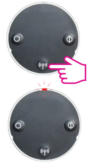 You have paired the unit to the thermostat when the unit LED goes off. Once paired, the unit operates in automatic mode and receives room temperatures from the thermostat.
Product Compliance & Safety Information
INTRODUCTION
The TRV10RFM is a battery-powered, mini-size thermostatic radiator valve (TRV) controller using ZigBee wireless communication. Simply replace the existing, passive head on the standard radiator valve with the TRV10RFM (referred to from now on as the unit). Use the unit with the VS10RF or VS20RF series of wireless thermostats and a Universal Gateway. 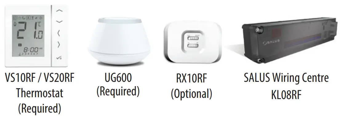
The SALUS TRV10RFM is compatible with the majority of thermostatic radiator valves. Before fitting, please check your valve is suitable for use with the SALUS TRV.
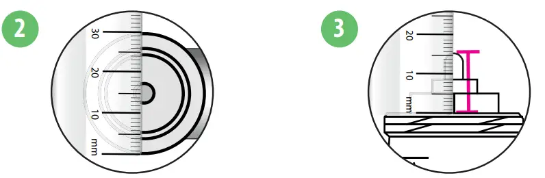 | |
| Measure the thread diameter (must measure 30mm) | Measure the pin length of the valve when it is in the open position. (must measure between 13-16mm) |
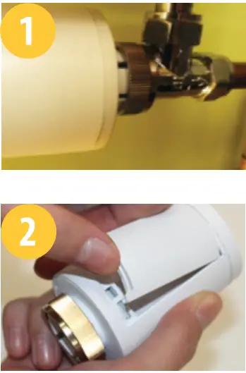
Installing the Unit
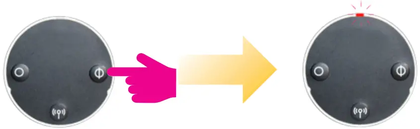
- Screw the units nut (finger tight) to the radiator valve and check that the LED is solid red.

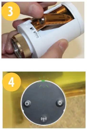
- Remove the battery door on the side of the unit.
- Insert the batteries, ensuring correct orientation.

- The LED on the unit flashes green then flashes red before changing to solid red. When it is solid red, place the unit over the radiator valve using the mounting ring if needed:
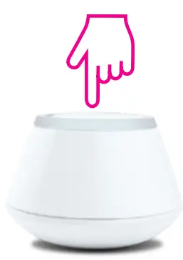
- Press any button on the unit to adapt it to the radiator valve. Once all adaptation noise and LED activity has stopped, the unit is ready to pair with your wireless thermostat.

- The unit is now ready for pairing to the SALUS thermostat. You may now start the pairing process.
Leaving the Network
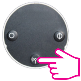
Once paired to a thermostat, press and hold the pairing button on the unit for 10 seconds.
The red LED come on together for one second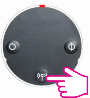 Note: After you have deleted the unit from the wireless network, you must reinstall the TRV see Installing the unit.
Using the Unit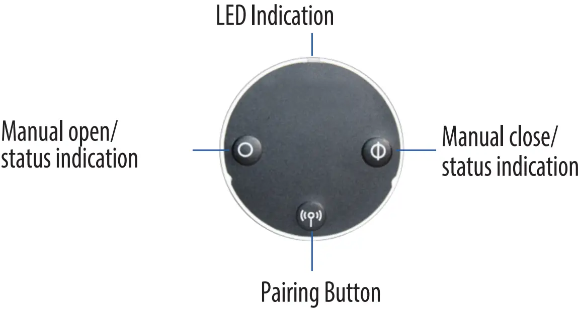 Using the Unit
Auto Lock Function
Auto lock function is disabled until you have gone through the pairing process. After pairing, the TRV will auto lock after 5 minute if no buttons have been pressed.
Unlocking the Buttons
To unlock the buttons, press the pairing and close buttons together for 3 seconds.
Opening the Valve Manually
Press the open button for 3 seconds. The LED flashes green once and the valve opens.
Closing the Valve Manually
Press the close button for 3 seconds. The LED flashes red once and the valve closes.
Entering Fail Safe Mode
In fail safe mode, the unit opens the valve 25% for water flow to maintain room temperature.
To enter fail safe mode, press and hold the open and close buttons together for 3 seconds.
To exit fail safe mode, press the:
- Pairing button to put the unit in automatic mode
- Open button for 3 seconds to open the valve
- Close button for 3 seconds to close the valve
Restoring Factory Default Settingse
Press the pairing, open, and close buttons together for 10 seconds.
Protecting against Frost
When you have manually closed the valve, the unit automatically enables frost protection. Frost protection starts only when the temperature in the room drops below the frost temperature setpoint. The unit does all this automatically when connected to a thermostat and you don’t have to do anything.
Detecting Open Windows
The unit checks the rate of temperature drop in the room in which it is located. If the drop is rapid, it assumes a window in the room has been opened. This only works if the unit is paired to the thermostat and is in automatic mode and the battery in the unit is not low. The unit does all this automatically when connected to a thermostat and you don’t have to do anything. It works between 0 and 40⁰C.
Protecting against Lime Scale
Do not leave a valve open for a long time because this could cause a build up of lime scale. The unit has a lime-scale protection feature to prevent against this. The valve motor automatically starts once a week if no valve movement has been detected within a 14- day period. Lime-scale protection will continue to operate in automatic, manual open, and manual close modes and you don’t have to do anything.
Auto Adaptation
Once the batteries are inserted into the unit, the red light will appear. If no keys are pressed it will auto adapt to the valv
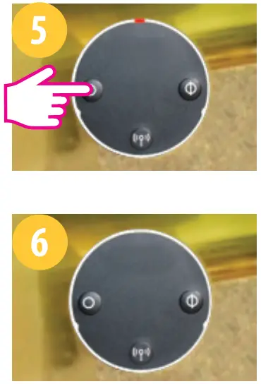
LED Indicators
| When… | The LEDs… | Valve | |
| Power switched on or after reset | Software Version indication | A sequence of red and green LEDs flashing displayed indicates the software version | |
| Unit adapting to valve | Red flashes then goes steady. Green flashes (or red flasheson failure to adapt). Green steady. Green and red flash (or red flashes on failure to adapt) | ||
| Unit has not joined network or has not paired to thermostat | Auto mode | Green and red flash alternately after short press on open or dose button | 25% open |
| Manual open | Green flashes twice after short press on open or dose button | 100% open | |
| Manual dose | Red flashes twice after short press on open or close button | 016open | |
| Unit paired to thermostat and in auto mode | No LED | ||
| Leaving network | Red and green on together for one second | ||
| Identifying the network | Green flashes for up to 10 minutes | ||
| Wireless link to thermostat lost | Auto mode | Green and red flash alternately after short press on open or dose button | |
| Manual open | Green flashes twice after short press on open or dose button | 100’36 open | |
| Manual dose | Red flashes twice after short press on open or dose button | 0% open | |
| Normal operation | Auto mode | Green flashes once after short press on open or dose button | 1 to 100% open |
| Auto mode Red flashes once after short press on open or close button | 0% open | ||
| Manual open | Green flashes twice after short press on open or dose button | 100’36 open | |
| Manual close | Red flashes twice after short press on open or dose button | 0% open | |
| Window open mode active | Green and red flash twice every 10 seconds | 10096 open | |
| Battery low | Red flashes three times every 10 seconds (less if the battery is low) | 25% open | |
| Error installing | Green and red flash alternately | ||
Technical Detail
| Model | TRV10RFM |
| Type | Hydraulic Radiator Valve DC Motor M30 x 1.5 |
| Input | Three push buttons: • Manual open/status indication • Manual close/status indication • Pairing |
| LED Indicator | Bi-Colour, Red/Green |
| Valve Adaptation | Automatic |
| Power Source | 2x AA Batteries |
| Battery Life | 14 Months (low battery indication) |
| Control Method | Modulating |
| Communication | 2.4GHz ZigBee wireless |
| Operating Temperature | 0 to 45ºC |
| Storage Temperature | -20 to 60ºC |
| Operating Humidity | 5 to 95”RH |
| IP30 | |
| H 88.6, W 51 |
| To do this… | Press the… |
| Leave the network | Pairing button for 10 seconds (when unit already in network) |
| Pair with thermostat | Pairing button for 10 seconds |
| Put unit in automatic mode | Short press Pairing button |
| Fully open the valve | Open button for 3 seconds |
| Fully close the valve | Close button for 3 seconds |
| Restore factory default settings | Open, pairing, and close buttons together for 3 seconds |
| Lock and unlock the buttons | Pairing and close buttons together for 3 seconds |
Manual Override
To remove the unit from auto mode, follow the steps below. If the buttons are locked, unlock them by pressing the pairing and close buttons together for 3 seconds.
 | |
| Press for 3 seconds to manually open | LED flashes green once and then goes out. To check status refer to table above. |
 | |
| Press for 3 seconds to manually close | LED flashes red once and then goes out. To check status refer to refer to table above. |
 | Short press to return to Auto mode. Red LED will flash once to confirm that the unit is in AUTO |
Warranty
SALUS Controls warrants that this product will be free from any defect in materials or workmanship, and shall perform in accordance with its specification, for a period of
five years from the date of installation. SALUS Controls sole liability for breach of this warranty will be (at its option) to repair or replace the defective product.
Customer Name: ……………..
Customer Address: ……………….
Post Code: ………………………………
Tel No: ………………………….
Email: …………………………………..
Engineers Company: ……………
Tel No: ……………………………….
Email: ……………………………….
Instalation Date: ………………..
Engineers Name: ……………………
Engineers Signature: …………
SALUS Controls
Units 8-10……………………
Northfield Business Park…………..
Forge Way…………………………
Parkgate…………………………
Rotherham………………………….
S60 1SD…………………………….
SALES:
T: +44 (0) 1226 323961
E: [email protected]
TECHNICAL:
T: +44 (0) 1226 323961
E: [email protected]
![]() SALUS Controls is a member of the Computime Group
SALUS Controls is a member of the Computime Group
Maintaining a policy of continuous product development
SALUS Controls plc reserves the right to change specification,
Design and materials of products listed in this brochure without prior notice.
Issue Date: Dec 201400086/2
www.salus-controls.com For PDF Instruction Manual go to www.salus.controls.com