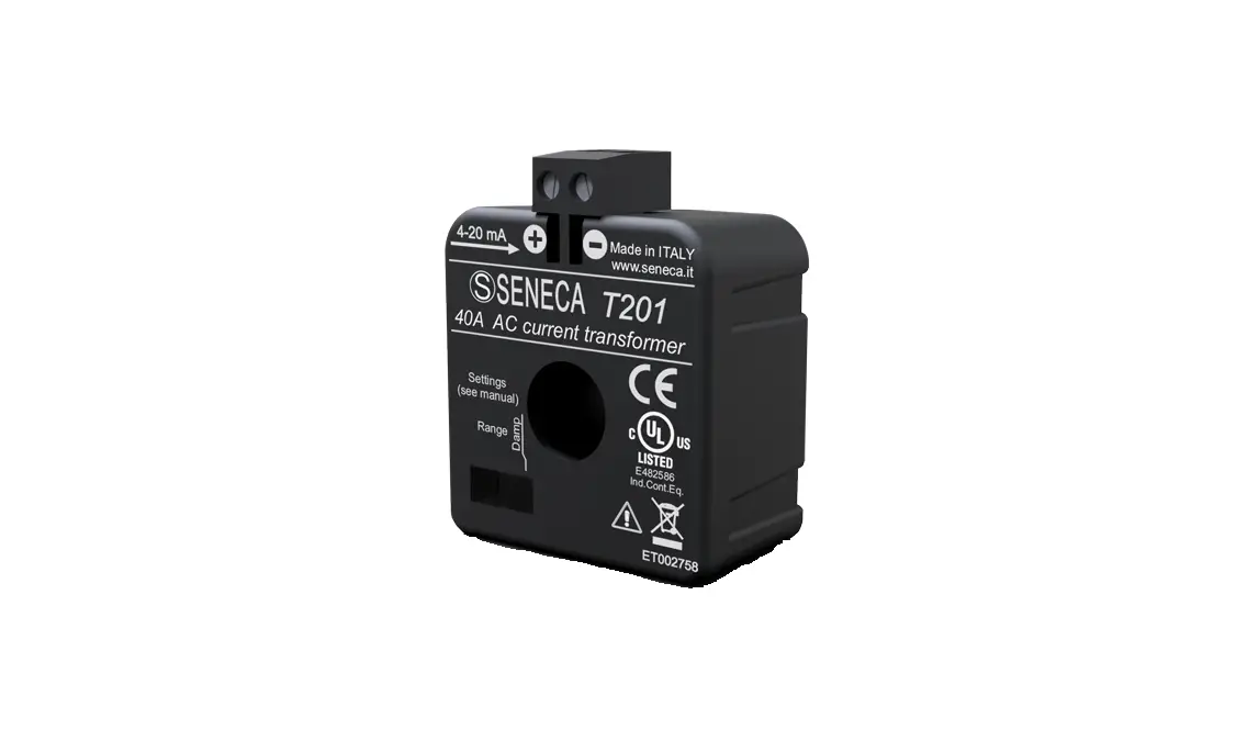
SENECA T201 2 Wire – Loop Alternated Current Transducer Instruction Manual
General Specifications
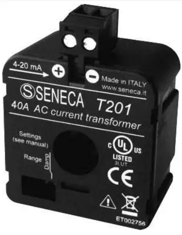
- The T201 instrument is an AC current transducer (CT) for 4 – 20 mA current loops (loop powered 2 wires technology).
- High precision.
- Extremely compact size.
- Wide configurability: eight pre-calibrated ranges, DIP-switch selected.
- Extremely low consumption.
- Low output ripple and quick response to variations.
- Damping filter (DIP-switches activable) to reduce the response time (damping starts, unstable loads, etc.).
Technical features
INPUT | ||
| Measure type | AC rectified average | |
| Range | 5 A, 10 A, 15 A, 20 A, 25 A, 30 A, 35 A, 40 A (DIP-switch selected). | |
| Peak factor | 2 | |
| Bandwidth | 20 – 1000 Hz | |
| Insulation | When a sheathed wire is used, the insulation voltage is set by sheath properties. On a bare wire, it’s stated 3 kV A. | |
| Over-current | 800 A permanent | |
OUTPUT AND POWER SUPPLY | ||
| Type | 4 – 20 mA, max. load R =600 Ω.Screw terminals: p and m. | |
| Terminals | Screw terminal pitch 5.08mm for max 2.5 mm² cables | |
| Hole diameter | 12.3 mm | |
| Power supply | 5 – 28 VC (between p and m.) | |
| Protections | – Polarity reversal – Over-Voltage | |
| Max. indication | < 28 mA | |
| ACCURACY (1) | ||
| Frequency: 40 – 400 Hz | Frequency: 20 – 1000 Hz | |
| Range < 5 A | 0.1 % o.m. + 0.1 % o.t.s. | 0.1 % o.m. + 0.3 % o.t.s. |
| Range > 5 A | 0.2 % o.m. + 0.1 % o.t.s. | 0.2 % o.m. + 0.3 % o.t..s. |
| Resolution | Infinity | |
| Temperature coefficient | < 150 ppm/°C. | |
| Error due to EMI | < 40 mA | |
| Response time | – Filter «fast»: 100 ms – Filter «slow»: 2500 ms | |
| Residue ripple | < 10 µA rms @ 20mA and 50 Hz | |
| Self-Consumption | < 50 mW | |
| Notes (1) | These acronyms apply: o.m. = of measurement, o.t.s. = of the scale. | |
OVERVOLTAGE CATEGORY | ||
| Bare conductor | CAT. III 300V | |
| Insulated conductor | CAT. III 600V | |
OPERATING CONDITION | ||
| Protection degree | IP20. | |
| Operating temperature | -20 – +70 °C. | |
| Storage Temperature | – 40 – +85 °C. | |
| Humidity | 10 – 90 % non-condensing | |
| Altitude | Up to 2000 m a.s.l. | |
CASE | ||
| Weight | 47 g. | |
| Overall dimensions | 41 x 44 x 26 mm (without terminals). | |
| Box material | PA6, black. | |
DIP-switches
Input Range | Filter (*) | |||||||||||
| SW 1 | 1 | 2 | 3 | Range | SW 1 | 1 | 2 | 3 | Range | SW 1 | 4 | |
| 5 A | 25A | Presen | ||||||||||
| 10A | 30A | Absent | ||||||||||
| 15A | 35A | |||||||||||
| 20A | 40A | |||||||||||
In the table the symbol ![]() corresponds to the switch in the ON position. The instrument is factory delivered with range 5A, 100ms filter. (*)The input filter slows down the response time to about 2.5 s and stabilizes the measurement.
corresponds to the switch in the ON position. The instrument is factory delivered with range 5A, 100ms filter. (*)The input filter slows down the response time to about 2.5 s and stabilizes the measurement.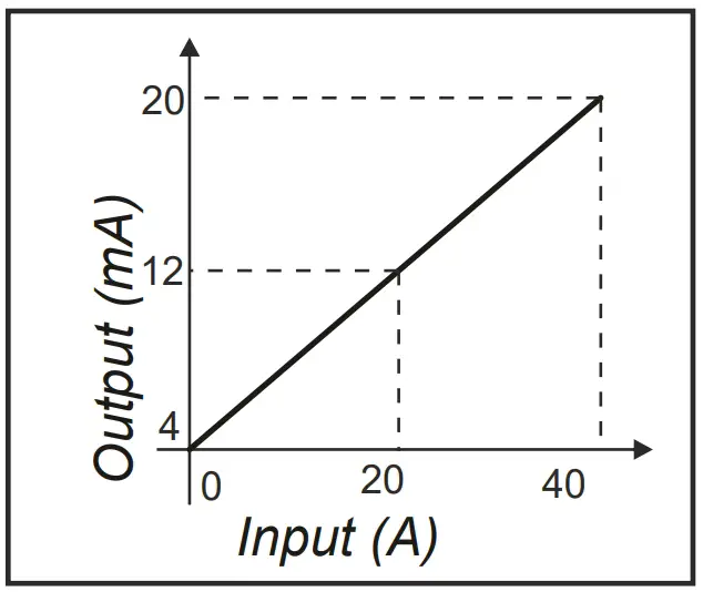
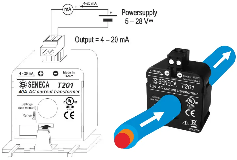
Mounting
The device can be located in any position and place, in accordance with the operating conditions above stated. Use the included holder bracket when fixing it to a DIN rail.
WARNING: High-strength magnetic fields may change the output value. Avoid closeness to permanent magnets, electromagnets or iron bulks that cause such a modification of the surrounding magnetic field; try a different arrangement or orientation if zero error was greater than expected.
Multi-turn primary winding to improve sensibility
You can increase the sensibility of the device simply passing several times in the hole with the measuring current, realizing turns with multiplicative effect: for example, passing 5 times in the hole, as to see 4 turns, choosing a 40 A range, you get an equivalent sensibility of 8 A full-scale. When you make this, let dispose the turns with symmetry in order to preserve accuracy: use diametric contraposition with 2 turns, cross disposition with 4 turns, 60° with 6 turns, and so on.
 Disposal of electrical & electronic equipment (applicable throughout the EU and other countries wit separate collection programs). This symbol, found on your product or on its packaging, indicates that this product should not be treated as household waste when you wish to dispose of it. Instead, it should be handed over to an applicable collection point for the recycling of electrical and electronic equipment. By ensuring this product is disposed of correctly, you will help prevent potential negative consequences to the environment and human health, which could otherwise be caused by inappropriate disposal of it. The recycling of materials will help to conserve natural resources. For more detailed information about the recycling of this product, please contact your local city office, waste disposal service or the retail store where you purchased this product.
Support
SENECA s.r.l.
Via Austria, 26 – 35127 – PADOVA – ITALY
Tel. +39.049.8705355 – 8705359
Fax +39.049.8706287
Manuals and configuration software are available at website: www.seneca.it/products/t201
Technical support: [email protected]
Product Information: [email protected]
This document is property of SENECA Srl. Duplication and reproduction are forbidden, if not authorized. Contents of the present documentation refers to products and technologies described in it. All technical data contained in the document may be modified without prior notice.Content of this documentation is subject to periodical revision.