![]() T201DCH50-M AC-DC Contactless TRMS Current Transducer
T201DCH50-M AC-DC Contactless TRMS Current Transducer
User Manual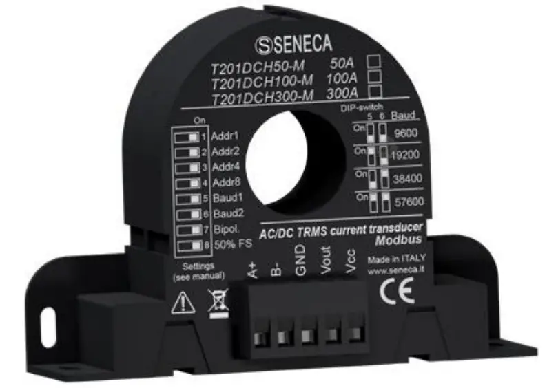
T201DCH50-M AC-DC Contactless TRMS Current Transducer
USER MANUAL
T201DCH50-M T201DCH100-M T201DCH300-M
AC/DC TRUE RMS or DC BIPOLAR CURRENT TRANSFORMER WITH RS485 PORT AND MODBUS RTU PROTOCOL
SENECA S.r.l. Via Austria 26 35127
Z.I. – PADOVA (PD) – ITALY
Tel. +39.049.8705355 8705355
Fax +39 049.8706287
ORIGINAL INSTRUCTIONS
Introduction
Contents of the present documentation refer to products and technologies described in it.
All technical data contained in the document may be modified without prior notice.
The content of this documentation is subject to periodical revision.
To use the product safely and effectively, read carefully the following instructions before use. The product must be used only for the use for which it was designed and built: any other use must be considered with full responsibility of the user.
The installation, programming, and set-up are allowed only to authorized operators, physically and intellectually suitable.
Set-up shall be performed only after a correct installation and the user shall perform every operation described in the installation manual carefully.
Seneca is not considered liable for failure, breakdown, or accident caused because of ignorance or failure to apply the indicated requirements.
Seneca is not considered liable for any unauthorized changes.
Seneca reserves the right to modify the device, for any commercial or construction requirements, without the obligation to promptly update the reference manuals.
No liability for the contents of these documents can be accepted.
Use the concepts, examples, and other content at your own risk.
There may be errors and inaccuracies in this document that may of course be damaging to your system.
Proceed with caution, and although this is highly unlikely, the author(s) do not take any responsibility for that.
Technical features are subject to change without notice.
| CONTACT US | |
| Technical support | [email protected] |
| Product information | [email protected] |
Document revisions
| DATE | REVISION | NOTES |
| 19/07/2017 | 1.0.0 | First revision. |
| 26/10/2017 | 1.0.1 | Added info for Reset Imin/imax commands. |
| 22/01/2018 | 1.0.2 | Changed Accuracy info. |
This document is property of SENECA srl. Duplication and reproduction are forbidden, if not authorized.
DEVICE DESCRIPTION AND INTENDED USE
![]() WARNING!
WARNING!
This User Manual extends the information from the Installation Manual about the device configuration. Use the Installation Manual for more info.![]() WARNING!
WARNING!
Under any circumstances, SENECA s.r.l. or its suppliers shall not be responsible for loss of recording data/incomes or for consequential or incidental damage due to neglect or reckless mishandling of the device, even though SENECA is well aware of these possible damages. SENECA, its subsidiaries, affiliates, companies of the group, its suppliers, and retailers shall not guarantee that the functions will satisfy completely customer’s expectations or that the device, the firmware, and the software shall have no errors or work continuously.
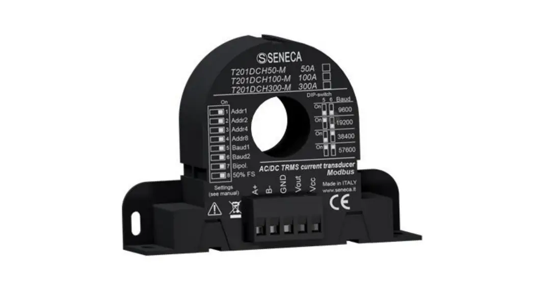
1.1. Description
The T201DCH50/100/300-M is an isolated, contactless loop-powered AC/DC current transducer. The look and device’s function are very similar to those of an active standard Current Transformer, but with the remarkable feature of measuring the DC and AC components. For its electrical endurance, ease of use, and compact dimensions, the T201DCH50-M, T201DCH100-M, and T201DCH300-M fit every kind of current measurement: up to 50 Adc/Aac, 100 Adc/Aac, and 300 Adc/Aac (respectively). An RS485 port with a standard Modus RTU protocol is also available.
The device can measure a current in 2 different modes (using dip switches or the Easy Setup Software):
- TRUE RMS AC/DC CURRENT MEASURE
- DC BIPOLAR CURRENT MEASURE (used also for obtaining the sign +/- of a DC current)
1.2. Features
- Similar usage to a standard alternating current active C.T.
- No shunt, no wasted power from the measuring circuit
- High accuracy rating (>2% FS): 0.3% for 50A and 100A models / 0.5% for 300A model.
- Suitable for use with all Seneca modules that allow to power the device with at least 12 Vdc and have a 0 10Vdc input
- Simple configurable with dip switches or with the free Easy Setup software
- Two ranges, dip-switch selectable
- Damping filter availability to improve stable reading
- Modbus RTU protocol by RS485 port
- Modbus Address/Baud Rate/Range/Mode configurable also from dip switch
- Suitable for batteries, battery chargers, solar panels, power units and generic dc and ac loads.
- Compact size: overall dimensions less than 96,5 x 68 x 26 mm
- Baud rate for Modbus RTU: from 1200 baud up to 115200 baud
- Start/Stop Input/Output Values configurable with Easy Setup software
- I Max/Min Resettable Modbus RTU registers available
- Quick installation on DIN 46277 rail
Refer to the installation manual for more information.
1.3. Technical specifications
| GENERAL SPECIFICATIONS | |
| Power supply | 11.5 – 28Vdc (between Vcc and GND) |
| Absorption max | 21mA (with no load) |
| BOX | |
| Dimensions | 96,5 x 68 x 26 mm |
| Hole Diameter | 20.8 mm |
| Box, protection degree | Black, PA6, IP20 |
| RS485 COMMUNICATION PORTS | |
| Number | 1 |
| Port | Modbus RTU Slave |
| Baudrate | 1200..115200 configurable |
| ENVIRONMENTAL CONDITIONS | |
| Temperature | -20°C ÷ +70°C |
| Humidity | 10 ÷ 90% no condensing |
| Storage temperature | -40°C ÷ +85°C |
| REFERENCE STANDARDS | |
| EN 61000-6-4 | Emission, industrial environmental |
| EN 61000-6-2 | Immunity, industrial environmental |
| EN 61010-1 | Safety |
Refer to the installation manual for more information.
CONFIGURING THE DEVICE
- The Device can be configured in two ways:
- A configuration from dip switches A full configuration from flash (using Easy Setup Software)
![]() WARNING!
WARNING!
Dip switches configuration are active only after a reboot!![]() WARNING!
WARNING!
The Dip Switch setting will overwrite the Flash setting so, if you need to use the flash configuration you MUST set ALL dip switches to “OFF”.
DIP SWITCH CONFIGURATION
3.1. Loading configuration from flash
If ALL Dip Switch 1…8 are OFF, the device uses the Flash configuration (you must use the Easy Setup Software for configuration)
| Load Configuration | DIP1 | DIP2 | DIP3 | DIP4 | DIP5 | DIP6 | DIP7 | DIP8 |
| FROM FLASH | OFF | OFF | OFF | OFF | OFF | OFF | OFF | OFF |
3.2. Setting the Modbus RTU Station Address
Dip Switch 1..4 are used for configuring the Modbus RTU Station Address:
Modbus RTU Address | DIP1 | DIP2 | DIP3 | DIP4 |
| 1 | ON | OFF | OFF | OFF |
| 2 | OFF | ON | OFF | OFF |
| 3 | ON | ON | OFF | OFF |
| 4 | OFF | OFF | ON | OFF |
| 5 | ON | OFF | ON | OFF |
| 6 | OFF | ON | ON | OFF |
| 7 | ON | ON | ON | OFF |
| 8 | OFF | OFF | OFF | ON |
| 9 | ON | OFF | OFF | ON |
| 10 | OFF | ON | OFF | ON |
| 11 | ON | ON | OFF | ON |
| 12 | OFF | OFF | ON | ON |
| 13 | ON | OFF | ON | ON |
| 14 | OFF | ON | ON | ON |
| 15 | ON | ON | ON | ON |
3.3. Setting the RS485 Baud rate
Dip Switch 5..6 are used for setting the Baud Rate
| Baud Rate | DIP5 | DIP6 |
| 9600 | OFF | OFF |
| 19200 | ON | OFF |
| 38400 | OFF | ON |
| 57600 | ON | ON |
![]() WARNING!
WARNING!
The Parity bit can not be configured with the dip switches configuration but only from the Easy Setup software. By setting the dip switches the parity is always set to “None” (8, N,1).
3.4. Setting the RMS/Bipolar mode and 50% – 100% full scale
Dip Switch 7: Select from True RMS Measure / Bipolar DC Measure Dip Switch 8: Select 50% of the full scale
The following figure is related to the RMS measure (“Bipol” dip switch 7 = OFF):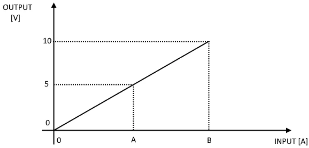
| MODEL | BIOL DIP7 SWITCH | 50% FS DIP8 SWITCH | A | B |
| T201DCH50-M | OFF | OFF | 25 A | 50 A |
| T201DCH50-M | OFF | ON | 12,5 A | 25 A |
| T201DCH100-M | OFF | OFF | 50 A | 100 A |
| T201DCH100-M | OFF | ON | 25 A | 50 A |
| T201DCH300-M | OFF | OFF | 150 A | 300 A |
| T201DCH300-M | OFF | ON | 75 A | 150 A |
The following figure is related to the Bipolar measure (“Bipol” dip switch 7 = ON):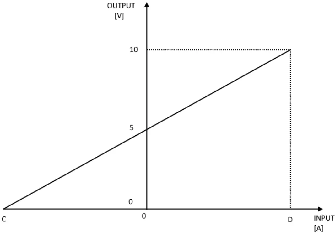
| MODEL | BIOL DIP7 SWITCH | 50%FS DIP8 SWITCH | C | D |
| T201DCH50-M | ON | OFF | -50 A | +50 A |
| T201DCH50-M | ON | ON | -25 A | +25 A |
| T201DCH100-M | ON | OFF | -100 A | +100 A |
| T201DCH100-M | ON | ON | -50 A | +50 A |
| T201DCH300-M | ON | OFF | -300 A | +300 A |
| T201DCH300-M | ON | ON | -150 A | +150 A |
![]() WARNING!
WARNING!
The dip switches configuration is active only after a reboot!
So, for example, using the RMS measure with 0 A input the Output voltage is 0V but using the Bipolar measure with 0 A input the Output voltage is 5V.
MODBUS RTU PROTOCOL
The Modbus protocol supported by the T201DCH50-100-300 is: Modbus RTU Slave For more information about these protocols, please refer to the Modbus specification website: http://www.modbus.org/specs.php.
4.1. Modbus RTU function code supported The following Modbus RTU functions are supported:
- Read Holding Register……….. (function 3) Max 5 Registers
- Write Single Register………………. (function 6)
- Write Multiple registers…………………….. (function 16) Max 2 Registers
![]() WARNING!
WARNING!
All 32 bits values are stored into 2 consecutive registers![]() WARNING!
WARNING!
You can Read a Maximum of 5 Modbus Registers with the Read Holding Register function (function 3)![]() WARNING!
WARNING!
You can Write a Maximum of 2 Modbus Registers with the Write Multiple Register function (function 16)
MODBUS REGISTERS TABLE
In the following table these abbreviations are used:
MS = Most significant
LS = Less significant
MSW = Most significant Word (16 bits)
LSW = Less significant Word (16 bits)
R = Read-only register
RW = Read and writeable register
RW* = Read and writeable register, the value can be stored in flash by using the store flash command
Unsigned 16 bits = Unsigned 16 bits register (from 0 to 65535)
Signed 16 bits = 16 bits register with sign (from -32768 to +32767)
Float 32 bits = Floating point single precision 32 bits (IEEE 754)
register 0x = Hexadecimal Value
| Register Name | Comment | Register Type | R/W | Default value or Start Value | Modbus Address | Register Offset |
| Machine ID | Module ID code | Unsigned 16 bits | R | – | 40001 | 0 |
| Firmware Revision | Firmware Revision Code | Unsigned 16 bits | R | – | 40002 | 1 |
| Command | This register is used for sending commands to the device. The following commands are supported: 49600 Store configuration in Flash 49568 Reset the Module | Unsigned | R/W | 0 | 40006 | 5 |
| 49920 Reset I max Value 49921 Reset I min Value After the command is xecuted the register will return to 0 value | ||||||
| Modbus Station Address | Modbus RTU station address | Unsigned 16 bits | RW* | 1 | 40033 | 32 |
| Baud Rate | RS485 Port Baud rate 0 = 4800 baud 1 = 9600 baud 2 = 19200 baud 3 = 38400 baud 4 = 57600 baud 5 = 115200 baud 6 = 1200 baud 7 = 2400 baud | Unsigned 16 bits | RW* | 3 | 40034 | 33 |
| Parity | Communication Parity Bit 0 = None (8,N,1) 1 = Even (8,E,1) 2 = Odd (8,O,1) | Unsigned 16 bits | RW* | 0 | 40035 | 34 |
| True RMS/Bipolar Mode | Select from True RMS or Bipolar DC measurement mode 0 = True RMS 1 = Bipolar DC | Unsigned 16 bits | RW* | 0 | 40036 | 35 |
| Filter | Select Filter level 0 = LOW RMS =1400 ms Response Time BIPOLAR = 78 ms Response Time 1 = HIGH RMS = 2900 ms response time BIPOLAR = 650 ms response Time | Unsigned 16 bits | RW* | 0 | 40038 | 37 |
| Model | Select the model | Unsigned 16 bits | RW* | 0 or 1 or 2 According to | 40039 | 38 |
| 0 = T201DCHSO-M 1 = T201DCH100-M 2 = T201DCH300-M | the model | |||||
| Start Input Scale | Select the Start Input Scale | Float32 | 0 A | 40041 (LSW) 40042 (MSW) | 40-41 | |
| Stop Input Scale | Select the Stop Input Scale | Float32 | 100.0 A | 40043 (LSW) 40044 (MSW) | 42-43 | |
| Start output Scale | Select the Start output Scale | Float32 | RIM’ | 0 V | 40045 (LSW) 40046 (MSW) | 44-45 |
| Stop output Scale | Select the Stop output Scale | Float32 | 10.0 V | 40047 (LSW) 40048 (MSW) | 46-47 | |
| Float Current Value [A] | Current Measure Value in floating point LSW-MSW [A] | Float32 | Cr | – | 40049 (LSW) 40050 (MSW) | 48-49 |
| Integer Current Value [A x100] | Current Measure Value in signed integer [A x100] For example: 18534 = 185.34 A -2500 = -25.00 A | Signed 1€ Bits | Cr | – | 40051 | 50 |
| Current MIN [A] | Minimum Current Value (use register Command for resetting the value) The value is set to 0 at the startup | Float32 | R | – | 40059 (LSW) 40060 (MSW) | 58-59 |
| Current MAX [A] | Maximum Current Value (use register Command to reset the value) The value is set to 0 at startup | Float32 | R | – | 40061 (LSW) 40062 (MSW) | 60-61 |
| Output Voltage [V) | Output Voltage | Float32 | R | – | 40063 (LSW) 40064 (MSW) | 62-63 |
| Inverse Float Current Value [A] | Current Measure Value in floating point MSW-LSW [A] Copy of Float Current Value Registers with Inverse (MSW-LSW) Floating Point | Float32 | R | – | 40065 (MSW) 40066 (LSW) | 64-65 |
FULL CONFIGURATION WITH EASY SETUP
To configure all the device parameters you must use the RS485 Port and the Easy T201DCH-M software included in the Easy Setup Suite. You can download the Easy Setup software for free from: www.seneca.it
6.1.Easy Setup Menu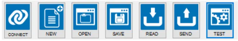 Connect: Use the connect icon to connect the PC to the Device. Note that you need an RS485 to USB converter like Seneca S117P1 or S107USB to connect the device to a PC. New: Load the default parameters in the actual project
Open: Open a stored project Save: Save the actual project
Read: Read the actual configuration from the device (if the dip switches are not ALL of the configurations is read from dip switches)![]() WARNING!
WARNING!
If you read a configuration from the device with at least one dip switch to “ON” the software will read the dip switch configuration because overwriting the flash configuration.
Send: Send the project configuration (if the dip switches are not ALL of the devices use the dip switch configuration and NOT the sent configuration)
Test: Start a Registers read, you can also reset the MIN/MAX values and start/stop a Datalogger
6.2. Creating a Project Configuration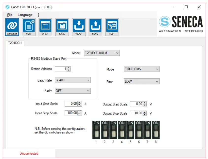
![]() WARNING!
WARNING!
You must set all dip switches to OFF before sending the configuration to the device or the actual configuration will be overwritten from the dip switches configuration!
The parameters that can be configured are:
Model: Select between the T201DCH50-M, T201DCH100-M, or T201DCH300-M model.
Station Address: Select The Modbus RTU station address
Baud Rate: Select the Baud rate from 1200 to 115200 baud
Parity: Select NONE, ODD, or EVEN
Mode: Select the current measure mode: True RMS or DC
Bipolar Filter: Select between LOW or HIGH:
| FILTER | RMS RESPONSE TIME (10%-90% F.S.) | BIPOLAR DC RESPONSE TIME (10%-90% F.S.) |
| LOW | 1400 ms | 78 ms |
| HIGH | 2900 ms | 650 ms |
Input Start/Stop Scale and Output Start/Stop Scale: Select the Start/Stop input and Output Start/Stop scale see figure: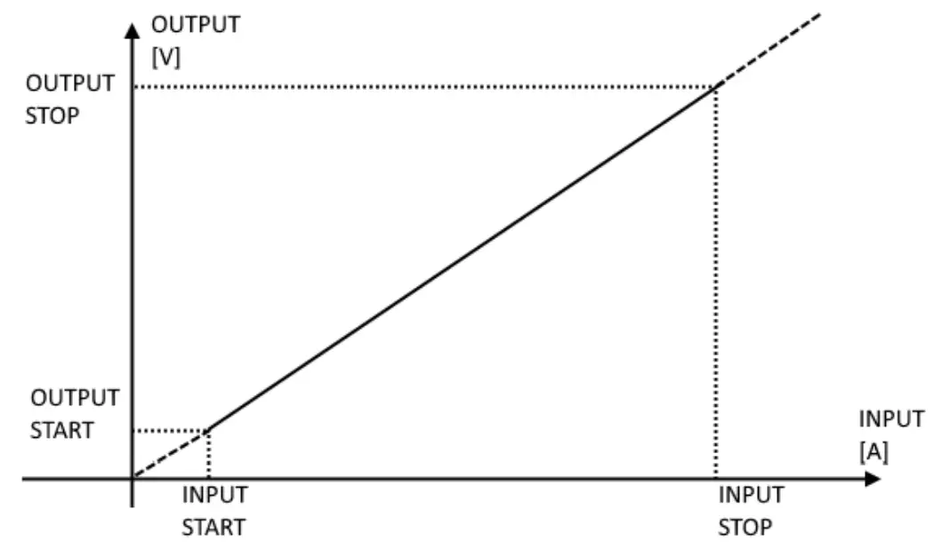 For example:
INPUT START = 20 A
INPUT STOP = 80 A
OUTPUT START = 2 V
OUTPUT STOP = 6 V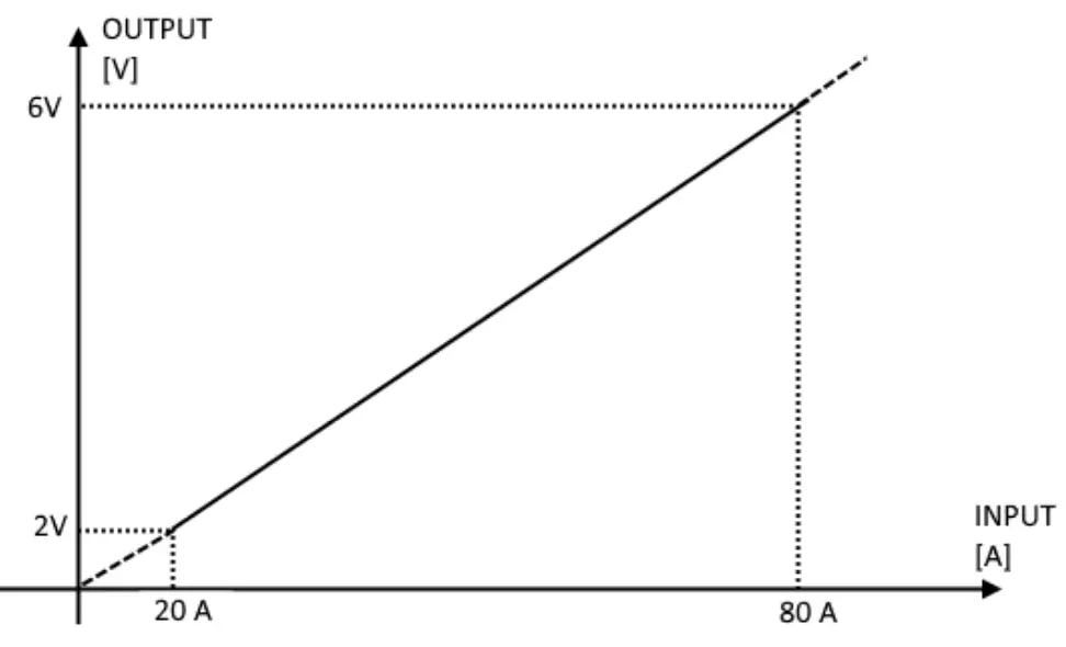 Note that with an input of 0 A the output is 0 V and over 80 A the output is over 6V (6V and 2V are not a limit).
![]() WARNING!
WARNING!
The Output Voltage is limited to about 10.8V
6.3. Testing the Device
When the configuration is sent to the device you can test the actual configuration by using the![]() icon:
icon: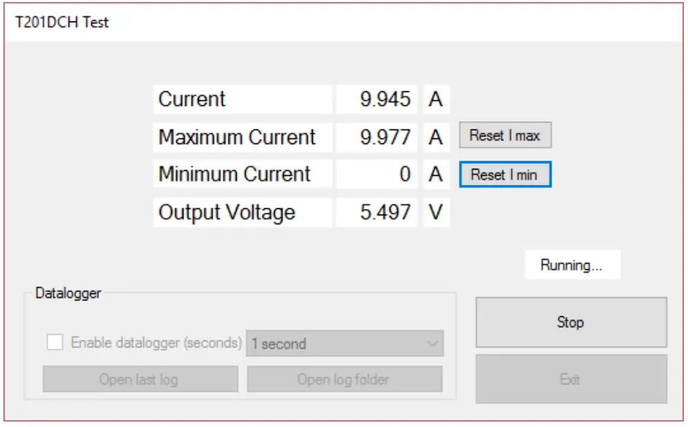 The test configuration will acquire the measure from the Modbus registers, you can also reset the MIN/MAX values.
6.3.1. The datalogger
The data logger can be used for acquiring data that can be used with external software (for example Microsoft Excel TM). It is possible to set how much time to acquire the samples (minimum 1 second):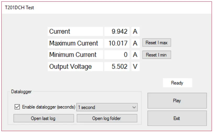
The data logger will create a file in a standard .csv format that can be opened with external tools: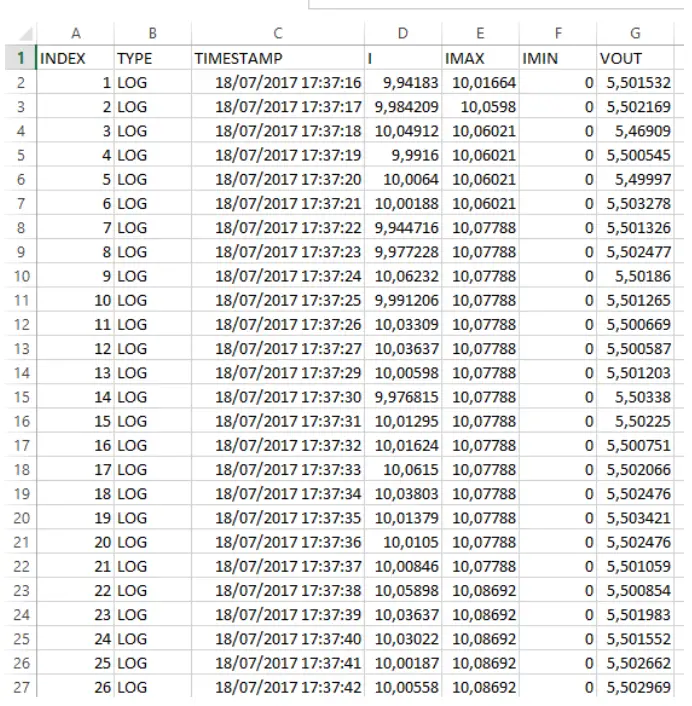 The file can also be opened with a text editor:
INDEX; TYPE; TIMESTAMP;I; IMAX; IMIN; VOUT
- ;LOG;18/07/2017 17:37:16;9,94182968139648;10,0166397094727;0;5,50153207778931
- ;LOG;18/07/2017 17:37:17;9,98420906066895;10,0598001480103;0;5,50216913223267
- ;LOG;18/07/2017 17:37:18;10,0491199493408;10,0602102279663;0;5,4690899848938
- ;LOG;18/07/201717:37:19;9,99160003662109;10,0602102279663;0;5,50054502487183
- ;LOG;18/07/2017 17:37:20;10,0064001083374;10,0602102279663;0;5,49996995925903
- ;LOG;18/07/2017 17:37:21;10,0018796920776;10,0602102279663;0;5,50327777862549
- ;LOG;18/07/2017 17:37:22;9,94471645355225;10,0778799057007;0;5,50132608413696
- ;LOG;18/07/2017 17:37:23;9,97722816467285;10,0778799057007;0;5,50247716903687
- ;LOG;18/07/2017 17:37:24;10,0623197555542;10,0778799057007;0;5,50186014175415
- ;LOG;18/07/2017 17:37:25;9,99120616912842;10,0778799057007;0;5,50126504898071
- ;LOG;18/07/2017 17:37:26;10,0330896377563;10,0778799057007;0;5,50066900253296
- ;LOG;18/07/2017 17:37:27;10,0363702774048;10,0778799057007;0;5,50058698654175
- ;LOG;18/07/2017 17:37:29;10,0059795379639;10,0778799057007;0;5,50120306015015
- ;LOG;18/07/2017 17:37:30;9,97681522369385;10,0778799057007;0;5,50337982177734
- ;LOG;18/07/2017 17:37:31;10,0129499435425;10,0778799057007;0;5,50225019454956
- ;LOG;18/07/2017 17:37:32;10,0162401199341;10,0778799057007;0;5,50075101852417
- ;LOG;18/07/2017 17:37:33;10,0614995956421;10,0778799057007;0;5,50206613540649
ACCESSORIES
For connecting T201DCH50-100-300-M to a PC you need an RS485 to USB converter. The RS485 to USB converters are:
7.1. Seneca S107USB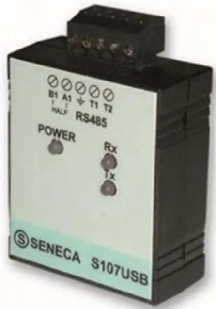 S107USB is an interface able to implement an RS485 serial port by using a PC USB port. The available drivers will recognize the serial interface as a standard serial port; so the use of the product is directly allowed through any software able to communicate with the standard serial ports of the operating system (COM1, COM2, etc). RS485 and USB ports are isolated from each other at 1500 V.
You can buy the Seneca S107USB also from our online store:
https://www.seneca.it/en/linee-di-prodotto/acquisizione-dati-e-automazione/moduli-dicomunicazione/convertitori-seriali-usb/s107usb
7.2. Seneca S117P1
S117P1 is a converter that realizes a serial connection via RS232, RS485, or TTL, using a USB port on the PC.
Through the drivers the operating system treats the serial interface like a standard serial port, allowing the use of the converter through any software that can communicate with the standard serial ports present in the operating system (COM1, COM2, etc.). RS232, RS485, and TTL ports are electrically isolated from the USB avoiding most of the problems of electrical noises. The package of the product includes a USB-miniUSB cable, serial cable Jack-DB9F, and programming cable RJ10-AMP
You can buy the Seneca S117P1 also from our online store:
https://www.seneca.it/en/linee-di-prodotto/acquisizione-dati-e-automazione/moduli-icomunicazione/convertitori-seriali-usb/s117p1
![]() wwktv.logicbusacom
wwktv.logicbusacom
[email protected]
+1 619 616 7350


