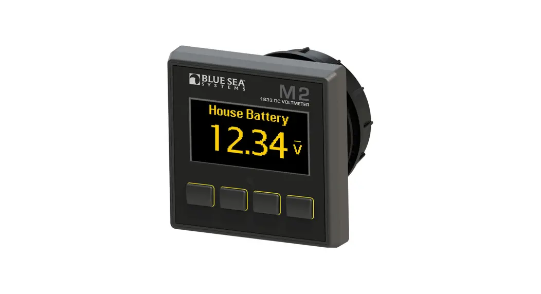
![]() M2 OLED
M2 OLED
Digital Monitor
QuickStart Installation Guide
1833 DC Voltmeter
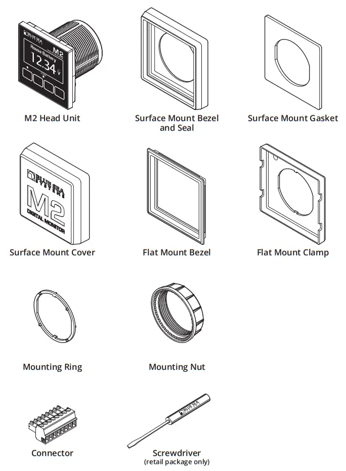
Components Included
360 Panel Mounting Kit 1525 (sold separately)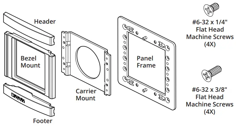
Connector Pin Assignment
| USB | Micro USB Port |
| 8 Pin Connector* | Function |
| 1 Required Connection | DC Negative |
| 2 Required Connection | DC Supply/Battery 3 + |
| 3 | Relay Output |
| 4 | Relay Supply/Battery 4 + |
| 5 | Battery 2 – |
| 6 | Battery 2 + |
| 7 | Battery 1 – |
| 8 | Battery 1 + |
*The 8 pin low voltage connector supports wire sizes from 16-26 AWG
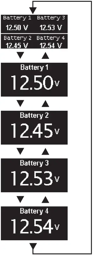
Screen Menu Functions
Press any button to bring up the menu.
- After start-up, press any button to access the menu.
- Press the UP or DOWN arrow buttons to scroll through menu windows.
- To set alarms and for more detailed information, see the online manual at bluesea.com/products/1833
System Overview
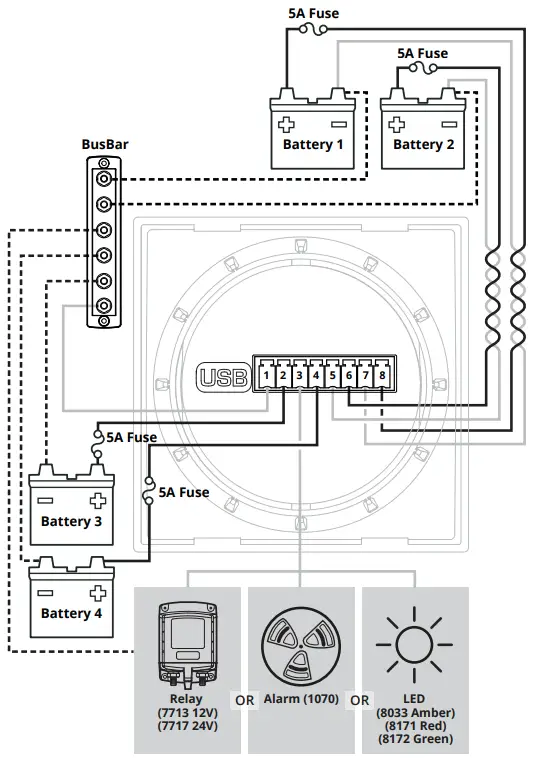
For the online manual that includes other configurations, go to bluesea.com/products/1833
Installation Steps
- Choose meter mounting style and location.
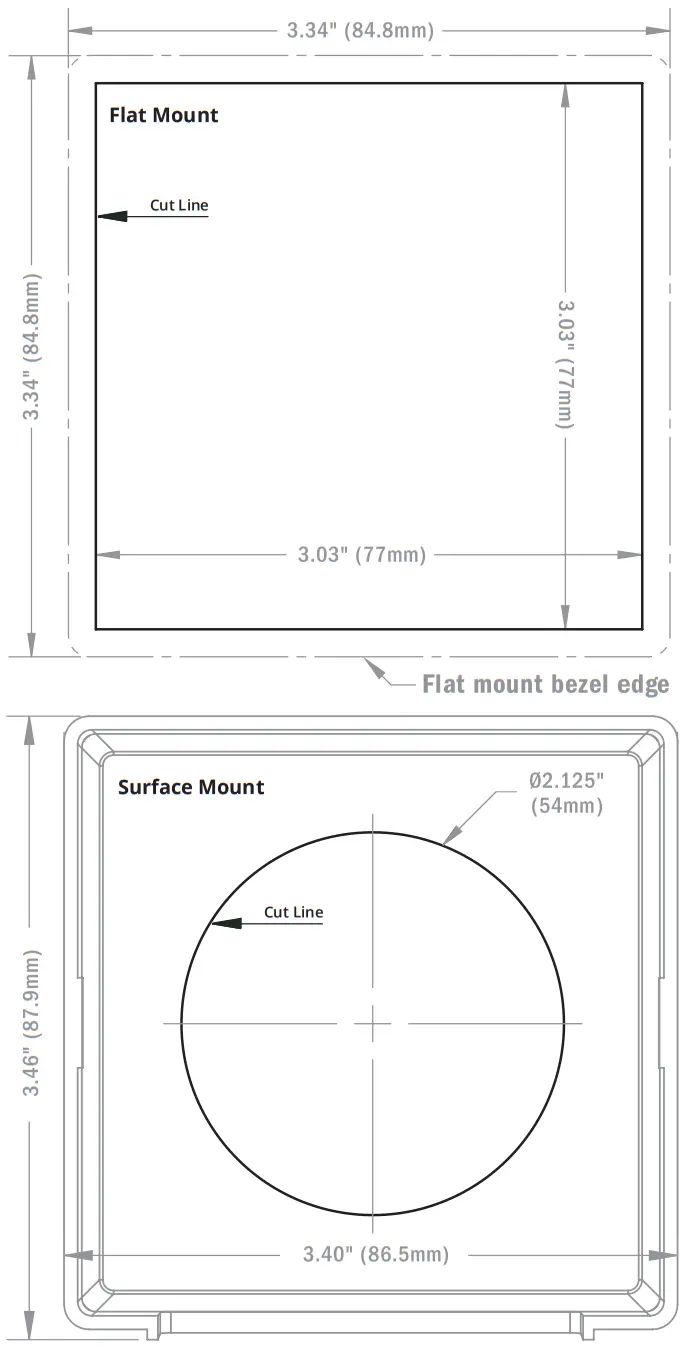
- Prepare mounting hole using cutout templates.
- Using wiring diagram:
• Install busbar, if needed.
• Make all connections to the meter’s connector.
Do not put fuses into fuse holders at this time. - Plug wired connector into the meter.
- Insert fuses into fuse holders, making the fuse to
Pin 2 (DC Supply/Battery 3+) Last.
Basic Meter Setup
- No special setup is required, however you may want to turn of unused inputs to prevent them from being displayed.
- To do this, go to the Setup Menu.
- Scroll to the unused Inputs (DC1, DC2, DC3, or DC4).
- Set Enabled to OFF.
- For more detailed information, or instructions regarding Alarm or Relay setup, see the full instructions found at bluesea.com/products/1833.
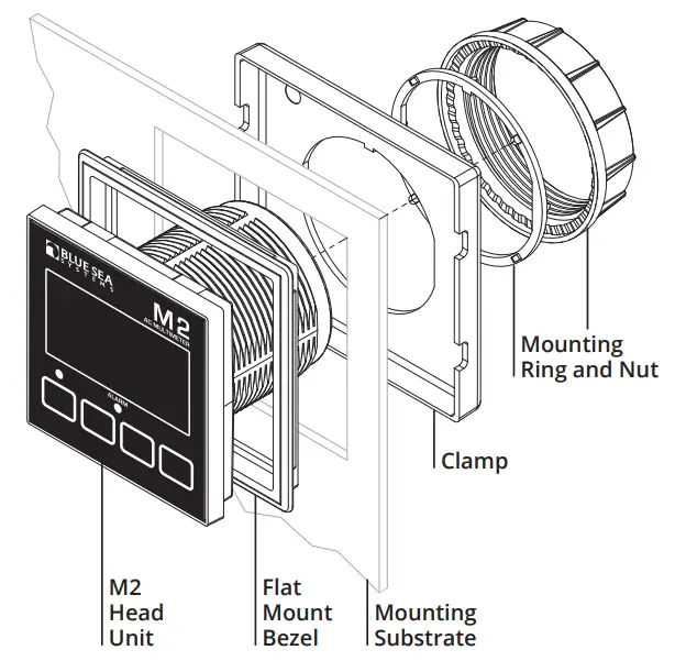
Mounting Options
Flat Mount
Surface Mount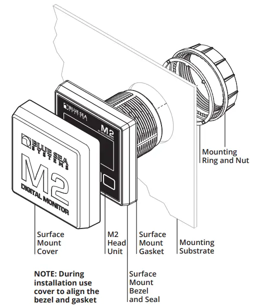
Mounting Templates
![]() WARNING
WARNING
The WARNING symbol refers to possible injury to the user or significant damage to the monitor if the user does not follow the procedures.![]() CAUTION
CAUTION
The CAUTION symbol refers to restrictions and rules with regard to preventing damage.
![]() WARNING
WARNING
- If you are not knowledgeable about electrical systems, have an electrical professional install this unit. The diagrams in these instructions pertain to the installation of the unit and not to the overall wiring of the vessel.
- Verify that no other DC or AC sources are connected to the vessel’s wiring before installing the unit.
![]() CAUTION
CAUTION
- The back of the unit is not waterproof. Do not install where the back of the monitor is exposed to water.
Warranty
The M2 OLED Digital Meters come with a 5 year manufacturer’s warranty. This means the meter is warranted to be free from defects in materials orworkmanship for 5 years from the date of first purchase. The warranty is limited solely to the cost of repair or replacement of the M2 Meter product. Costs associated with labor or shipping of the defective parts are not covered. Blue Sea Systems cannot accept liability for damage due to the misuse of the M2 Meter.
Click here for more information at bluesea.com/products/1833 https://www.bluesea.com/products/1833
![]() bluesea.com
bluesea.com
980020420 Rev.004


