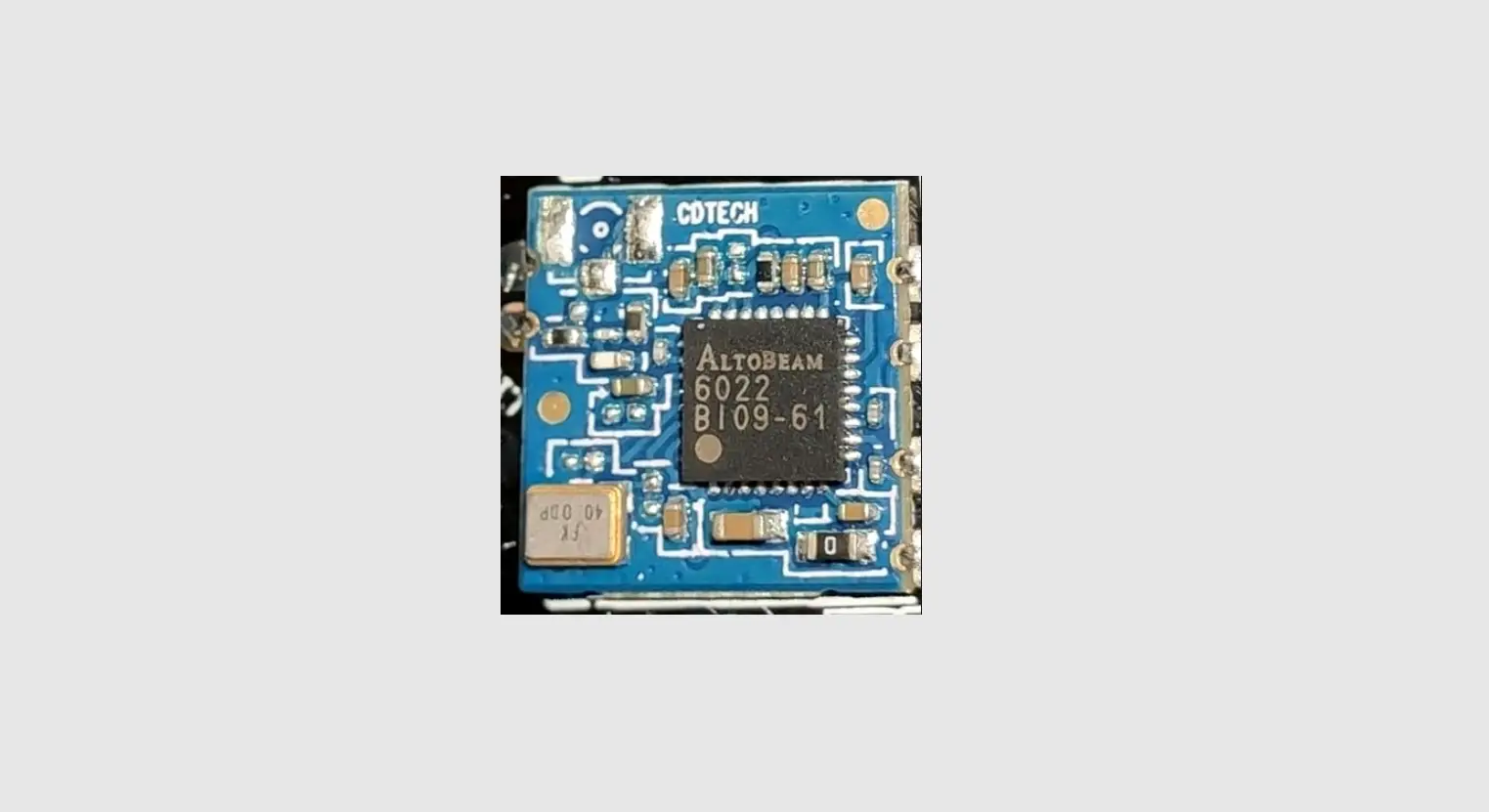
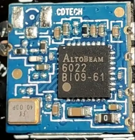
Altobeam ATBM6441 Wireless Module
Overview
The ATBM6441 module can be used in battery-powered Wireless cameras, Smart bells and other devices that need to connect to Wi-Fi networks. In order to allow you to install and use the product easier, please read this manual carefully.
Product characteristics
- Support Wi-Fi 2.4GHz IEEE 802.11b/g/n, 1T1R
- Operating frequency: 2.412 ~ 2.462GHz
- Modulation
- 802.11b: CCK (11, 5.5Mbps), QPSK (2Mbps), BPSK (1Mbps)
- 802.11g/n: OFDM
- PHY data rates
- 802.11b: 11, 5.5, 2, 1Mbps
- 802.11g: 54, 48, 36, 24, 18, 12, 9, 6Mbps
- 802.11 n: up to 150Mbps
- SDIO 2.0 interface
Product parameters
- Operation voltage: 3.3VDC
- SDIO 2.0 compliant
- Security: WEP, TKIP, AES, WPA, WPA2, WPA3
- OS support: Linux/Android/RTOS
- Power consumption: 3.3VDC [email protected] Max
- Operating temperature: -40 to +85℃
- Storage temperature: -60 to +150℃
- Humidity: 5% to 90% maximum
- Dimension: 12.0mm*12.0mm (L*W)
Pin definition
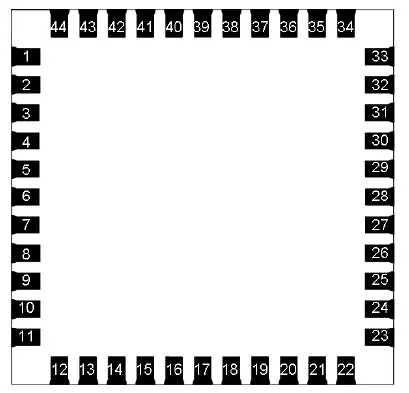
| Pin Number | Pin Name | Pin Description |
| 1 | GND | Ground |
| 2 | WL_ANT | External Antenna (2.4GHz 50ohm) |
| 3 | GND | Ground |
| 4 | MEAS2 | Two channels 10bits ADC input, input range is 0 to 1.1V. Detect battery power. |
| 5 | MEAS1 | Two channels 10bits ADC input, input range is 0 to 1.1V. Detect battery power. |
| 6 | GPIO10 | GPIO |
| 7 | GPIO11 | GPIO |
| 8 | NC/BOOT | BOOT_SEL pin for firmware download control, NC is default for normal operation. |
| 9 | VDD33 | 3.3V DC power supply input |
| 10 | GPIO9 | GPIO |
| 11 | GPIO7 | GPIO |
| 12 | POWER_ON | Hardware reset and internal regulator disable pin, low level is chip power down. |
| 13 | GPIO5 | GPIO |
| 14 | SDIO D2 | SDIO data line 2 |
| 15 | SDIO_D3 | SDIO data line 3 |
| 16 | SDIO_CMD | SDIO command line |
| 17 | SDIO_CLK | SDIO clock line |
| 18 | SDIO_D0 | SDIO data line 0 |
| Pin Number | Pin Name | Pin Description |
| 19 | SDIO_D1 | SDIO data line 1 |
| 20 | GND | Ground |
| 21 | NC | |
| 22 | VIDEO | 3.3V DC power supply input for I/O. Doesn’t support 1.8V I/O. |
| 23 | NC | |
| 24 | NC | |
| 25 | NC | |
| 26 | NC | |
| 27 | NC | |
| 28 | NC | |
| 29 | 32K_IN | External 32.768K crystal |
| 30 | 32K_OUT | External 32.768K crystal |
| 31 | GND | Ground |
| 32 | NC | |
| 33 | GND | Ground |
| 34 | GPIO12 | GPIO |
| 35 | NC | |
| 36 | GND | Ground |
| 37 | UART_TXD | GPIO0/UART_TXD |
| 38 | UART_RXD | GPIO1/UART_RXD |
| 39 | GPIO19 | GPIO |
| 40 | GPIO20 | GPIO |
| 41 | NC | |
| 42 | NC | |
| 43 | NC | |
| 44 | NC |
FAQ
Q: Why SDIO cannot be connected?
- A: a) Please check if the 3.3V DC power of the module is supplied.
- b)Please check if SDIO lines are connected correctly.
Q: Why cannot connect to the wireless router?
- A: Please check if the antenna is connected.
Warning
- Do not use this product under humid or hot conditions.
- Do not use overloaded.
FCC compliance statement
This device complies with Part 15 of the FCC Rules. Operation is subject to the following two conditions: (1) this device may not cause harmful interference, and (2) this device must accept any interference received, including interference that may cause undesired operation. Any changes or modifications not expressly approved by the party responsible for compliance could void the user’s authority to operate the equipment. This equipment has been tested and found to comply with the limits for a Class B digital device, pursuant to Part 15 of the FCC Rules. These limits are designed to provide reasonable protection against harmful interference in a residential installation. This equipment generates, uses and can radiate radio frequency energy and, if not installed and used in accordance with the instructions, may cause harmful interference to radio communications. However, there is no guarantee that interference will not occur in a particular installation.
If this equipment does cause harmful interference to radio or television reception, which can be determined by turning the equipment off and on, the user is encouraged to try to correct the interference by one or more of the following measures:
- Reorient or relocate the receiving antenna.
- Increase the separation between the equipment and receiver.
- Connect the equipment into an outlet on a circuit different from that to which the receiver is connected.
- Consult the dealer or an experienced radio/TV technician for help.
FCC regulatory compliance statement
Statement
This device complies with Part 15 of the FCC Rules. Operation is subject to the following two conditions: (1) this device may not cause harmful interference, and (2) this device must accept any interference received, including interference that may cause undesired operation.
Information to user
Warning: changes or modifications not expressly approved by the party responsible for compliance could void the user’s authority to operate the equipment. This module has been approved to operate with the antenna types listed below, with the maximum permissible gain indicated.
List of applicable FCC rules
- 47 CFR Part 15, Subpart C 15.247
Summarize the specific operational use conditions
- This module can be used in household electrical appliances as well as IP cameras and Smart doorbells. The input voltage of the module should be 3.0-3.6V.
Limited module procedures
- This module is a limited module.
Trace antenna designs
- The antenna is not a trace antenna.
RF exposure considerations
This Module complies with FCC radiation exposure limits set forth for an uncontrolled environment. This equipment should be installed and operated with a minimum distance of 20cm between the radiator and your body. This transmitter must not be co-located or operating in conjunction with any other antenna or transmitter.
Antennas
- No antenna on the module, a Dipole antenna with 3dBi gain was used during the test.
Label and compliance information
Please notice that if the FCC identification number is not visible when the module is installed inside another device, then the outside of the device into which the module is installed must also display a label referring to the enclosed module. This exterior label can use wording such as the following: “Contains FCC ID: 2AOXX-ATBM6441” any similar wording that expresses the same meaning may be used. Labeling requirements shall comply with the end-user device. Labeling rules for special devices, please refer to §2.925, § 15.19 (a)(5), and relevant KDB publications. For E-label, please refer to §2.935.
Information on test modes and additional testing requirements
The OEM integrator is responsible for ensuring that the end-user has no manual instruction to remove or install-module.
The module is limited to installation in mobile applications, a separate approval is required for all other operating configurations, including portable configurations with respect to §2.1093 and different antenna configurations.
Test software
- This module can use AT command via the UART interface to do tests.
Additional testing, Part 15 Subpart B disclaimer
This transmitter module is tested as a subsystem and its certification does not cover the FCC Part 15 Subpart B (unintentional radiator) rule requirement applicable to the final host. The final host will still need to be reassessed for compliance to this portion of rule requirements if applicable. As long as all conditions above are met, further transmitter test will not be required. However, the OEM integrator is still responsible for testing their end-product for any additional compliance requirements required with this module installed.


