![]()
Copyright Protection: Confidential – ISO 16016
| Date: 2021-12-08 No.: Page 1 | |
| Subject: RS 5.4 – Advanced driver assistance system – User’s Guide Ref.: |
RS 5.4 – User’s Guide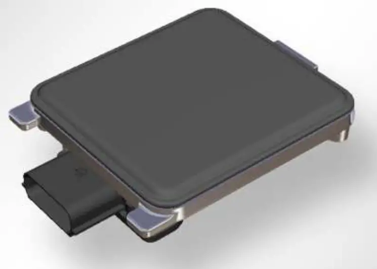
The RS 5.4 is an advanced driver assistant system, to warn the driver of the ego vehicle against potential collisions with other road users to the side, to the rear and to the front of the ego vehicle.
This system is not meant to encourage aggressive driving. The absence of a warning will not guarantee the absence of other road users. Responsibility for the safe operation of the vehicle remains with the driver.
| signed by: | checked by: |
| Subject: RS 5.4 – Advanced driver assistance system – User’s Guide = | Date: 2021-12-08 | |
| No.: | ||
| Page 2 of 8 |
Functions
The sensor is capable to detect moving objects. With this recognition capability, it covers the following functionality:
1.1 LCW
LCW (Lane Change Warning) is the feature used for recognition of target vehicles in the blind spot zone or in further distance in order to inform the driver of the ego vehicle about the safety level of a lane change. In case that a target vehicle approaches the ego vehicle in that way, that the lane change is no longer safe, a warning lamp is activated. If the driver of the ego vehicle decides to change the lane in such a dangerous situation, a warning can be given by setting the warning LED to blink.
Other HELLA terms are BSD = Blind Spot Detection and LCA = Lane Change Assistant
1.2 CTA
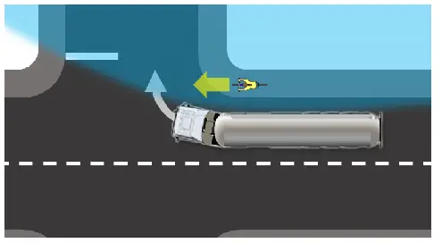
The City Turn Assist is the function of supporting the truck driver during turning maneuvers and keeping an overview of the blind spot zone of the truck. In HELLA terminology there is a risk of mixing the abbreviation “CTA” with the Cross-Traffic Alert function, which is referring to rear cross-traffic warnings. Therefore the City Turn Assist is often abbreviated as “TA”.
1.3 FTA
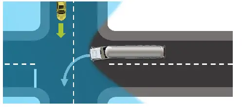
The Front Traffic Alert (also known as Front Cross Traffic Alert (FCTA)) supports the driver on traffic in front of the vehicle, which is especially helpful on the driver diverted side.
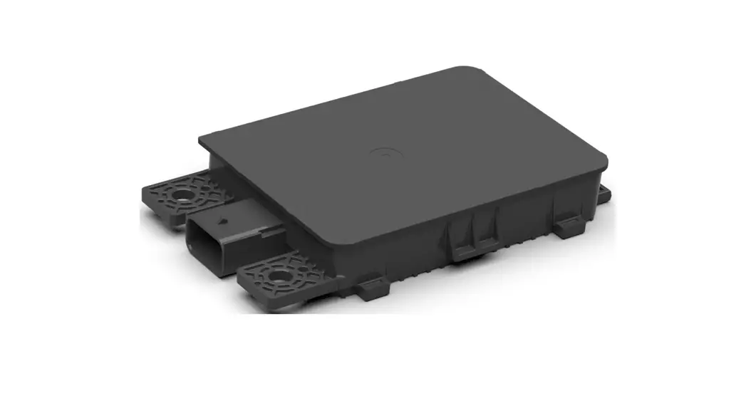
System Architecture
The system consists of two or more radar sensor units that are mounted in the front or rear corners of a vehicle or on the left and right sides of a vehicle so that the respective peripheral sectors of the vehicle can be observed.
The units interchange data between each other and the vehicle via the sensor CAN-bus. All units incorporate an RF part and a microcontroller to perform the radar signal processing.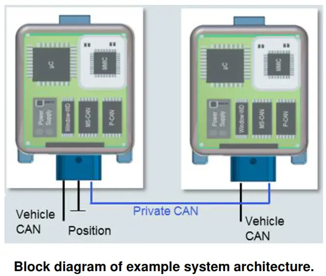
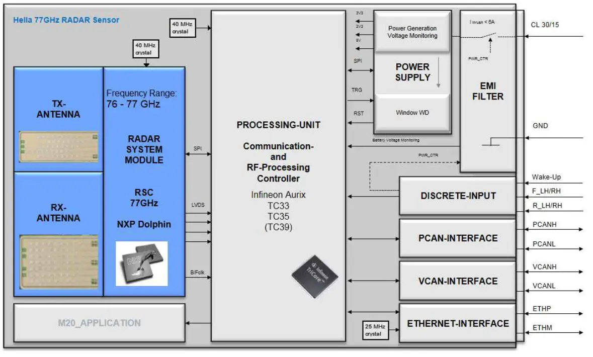
Block diagram of one radar sensor unit shows RF part and microcontroller part.
Each unit contains the following RF parts:
- one VCO,
- two transmitters (consisting of the power amplifier and antenna)
- four receivers (each consisting of an antenna, mixer, BPF, and base-band amplifier).
The transmit signal is generated by the VCO. The VCO frequency is controlled by a PLL.
Each transmit antenna is a microstrip patch antenna array with 1×6 elements. It is designed to illuminate a broad field of view and is thus a medium gain antenna. The receive antennas are also microstrip patch antennas with a medium gain (each 1×6 elements). The receivers down-convert the receive signals directly to zero-IF by using the VCO signal. The base-band receive signals are finally digitized by ADCs.
Technical Data
| Supply voltage | +9 V … +32 V |
| Power consumption | Typ. 4 W |
| Operating frequency range | 76000 MHz … 77000 MHz |
| Modulation bandwidth | < 1000 MHz |
| Modulation | FMCW (fast chirps) |
| Antenna feed power | < 10 dBm average |
| Antenna type | Microstrip patch array |
| Transmit antenna gain | 14 dBi |
| Operating temperature range | -40°C … +85°C |
Abbreviations
| ADC | Analog-to-digital converter |
| BPF | Bandpass filter |
| FMCW | Frequency modulated continuous wave |
| IF | Intermediate frequency |
| PLAN | Private controller area network |
| RF | Radiofrequency |
| Rx | Receive |
| Tx | Transmit |
| V | Vehicle controller area network |
| VCO | Voltage-controlled oscillator |
| WD | Watchdog |
Vehicle Integration
Due to the fact that RADAR waves can penetrate plastics, the sensor integration is possible behind the bumper fascia and thus invisible from the exterior. However, the plastic and other materials which surround the sensor may cause bending, refraction and reflection of the RADAR waves. Distances, clearances, selected radii and other constructive elements in their arrangement can lead to constructive or destructive interference of the RADAR waves. In case of an unfavourable configuration of all parameters towards each other, the sensor properties can be influenced disadvantageously. For these reasons, a generally valid positioning guideline covering all possible configurations and degrees of freedom and guaranteeing undisturbed sensor properties cannot be given.
The sensors should be positioned in the vehicle at a height of 400 to 700 mm above the road surface. If the sensor is positioned too close above the road surface, increased road reflections may appear Thus, an installation height as high as possible must be aimed for.
If the height specification cannot be fulfilled, then the planned installation height must be evaluated and agreed upon with Hella GmbH. & Co. KGaA. The amount of road reflections can for example be reduced by inserting a special additional shield below the radar sensor.
Spatial orientation of the sensors
The RS5.4 sensors can be mounted in the front, lateral and/or rear area of a vehicle under defined angles.
Examples for typical integration: Lateral/ side integration: 85…95 deg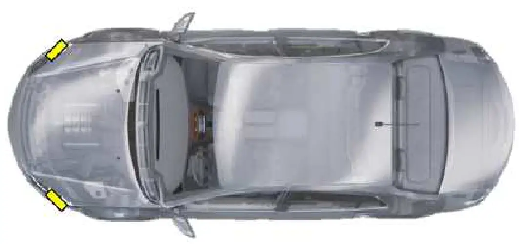
Rear side integration: 45 deg (depending on required field of view) 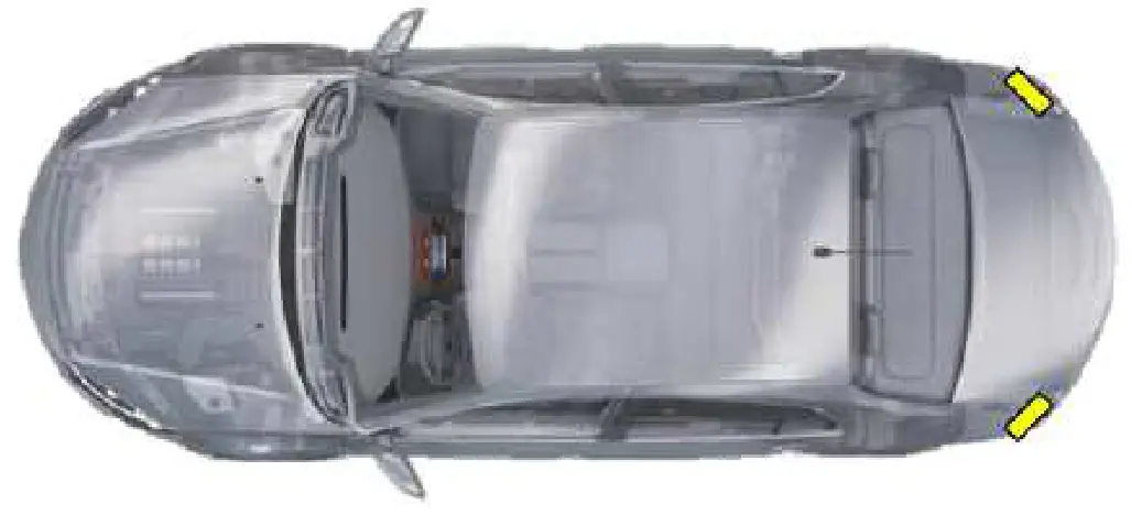
Front side integration: 45 deg (depending on required field of view)
Legal text requirements
Note: This User’s Guide is not intended for the end-user. The RS5.4 Advanced Driver Assistance System is not sold separately from the vehicle. All the full legal texts must be provided by the OEM in the User’s Manual of the vehicle.
USA: Changes or modifications not expressly approved by the party responsible for compliance could void the user’s authority to operate the equipment.
This device complies with part 15 of the FCC Rules. Operation is subject to the following two conditions: (1) This device may not cause harmful interference, and (2) this device must accept any interference received, including interference that may cause undesired operation.
Radiofrequency radiation exposure Information:
This equipment complies with FCC radiation exposure limits set forth for an uncontrolled environment. This equipment should be installed and operated with a minimum distance of 20 cm between the radiator and your body. This transmitter must not be co-located or operating in conjunction with any other antenna or transmitter. Canada (both English and French language required): This device contains license-exempt transmitter(s)/receiver(s) that comply with Innovation, Science, and Economic Development Canada’s license-exempt RSS(s). Operation is subject to the following two conditions:
- This device may not cause interference.
- This device must accept any interference, including interference that may cause undesired operation of the device.;
This equipment complies with ISED radiation exposure limits set forth for an uncontrolled environment.
This equipment should be installed and operated with a minimum distance of 20 cm between the radiator and your body. This transmitter must not be co-located or operating in conjunction with any other antenna or transmitter.
This document is confidential. Its contents are not to be exploited, passed on or disclosed to third parties without our express permission. All rights are reserved.
Hella 3399DE (2000-05)
Signed by:…………………….
Checked by:…………………


