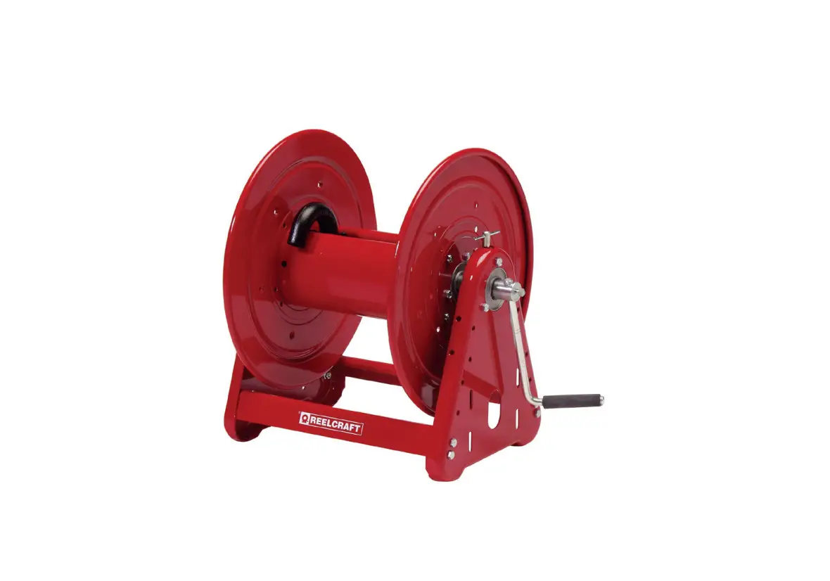
REELCRAFT Series 30000 Hand Crank Hose Reels High Pressure Wash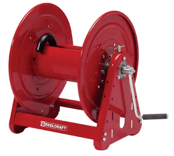
Dimensional Data
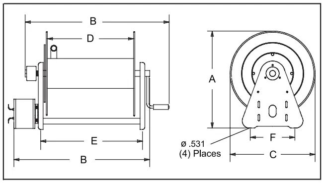
| CA38106 M | CA38112 M | CA38118 M | |
| A | 20 1/4” | 20 1/4” | 20 1/4” |
| B | 19 3/4” | 25 3/4” | 31 3/4” |
| C | 17 3/4” | 17 3/4” | 17 3/4” |
| D | 6” | 12” | 18” |
| E | 9 3/4” | 15 3/4” | 21 3/4” |
| F | 9” | 9” | 9” |
Safety Precautions
Personal injury and/or equipment damage may result if proper safety precautions are not observed.
- Ensure that the reel has been properly installed before connecting supply line (see installation instructions).
- Bleed fluid/gas pressure from system before servicing reel.
- Before connecting reel to supply line ensure that supply line pressure does not exceed maximum rated working pressure of reel.
- Do not play pranks on other personnel.
Even low pressure is very dangerous and can cause irrepairable damage or death. - Do not wear loose fitting clothing while operating reel.
- Be aware of other personnel in work area.
- Be aware of other machinery in work area.
- If a leak occurs in the hose or reel, remove supply line pressure immediately.
- If the reel is power driven check for loose, frayed, and/or broken wires before operating.
- Treat and respect a hose reel as any other piece of machinery, observing all common safety practices.
INSTALLATION INSTRUCTIONS
Inspection
Unpack and inspect the reel for damage.
Turn the reel by hand to check for smooth operation. Check for completeness.
Mounting of all hose reels
NOTE: Ensure that mounting surface is flat to prevent binding on reel after it is mounted.
- Two 1/2” diameter mounting holes are located at the base of each side support panel (2 each). Mount reel using four (customer supplied) bolts; tightening them securely to ensure a solid, rigid attachment.

- Perform the following steps only after all other installation steps, pertaining to your particular reel, are accomplished. Refer to page 4 for special instructions.
NOTE: A flexible hose connection must be used to compensate for any offset between the supply line and the reel swivel. - Apply thread compound to all threads.
- Thread male connector of supply line into swivel. Tighten securely.
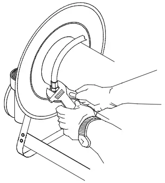
Connecting the hose
CAUTION: Do not connect the hose to the connecting tube assembly until after hose reel has been installed. Fully extend and charge hose before winding on to reel.
Momentarily open control valve, when initially charging, to purge hose of gases. When fluid appears at control valve, close valve. This prevents flattening of the hose and excessive pressure on the drum when fluid supply is reinitialized at a later time.
- Apply thread compound to all threads.
- Hand thread male hose connector into connecting tube assembly.
- Using a wrench, firmly hold onto connecting tube assembly while tightening hose connector.

OPERATING INSTRUCTIONS
WARNING-PREVENT STATIC SPARKING: When working around flammable liquids such as solvents, paints, chemicals or petroleum products, ensure that the hose reel, hose and the equipment being serviced are properly grounded.
Use grounded hose(s) (static wire). Use an ohmmeter to check continuity of the ground circuit. Fire and/or explosion can result if proper grounding is not achieved.
If reel is power or air driven, be careful of chain/sprocket drive system. Keep hands clear. Do not wear loose fitting clothing. Pull hose from the reel by grasping the hose itself, not the control handle or swivel.
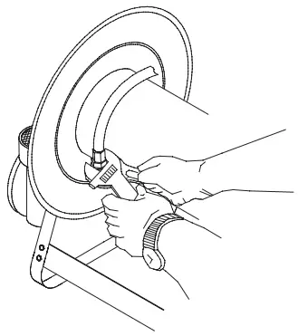
SERVICE INSTRUCTIONS
Replacing the hose
- Using a wrench, firmly hold onto the connecting tube assembly while removing hose connector.
- Follow procedures for “Connecting the hose” (refer to installation instructions).

Replacing the swivel
CAUTION: Remove supply line pressure before performing the following procedure.
- Remove supply line from swivel.
- Remove swivel assembly from inlet shaft.
- Install swivel assembly to inlet shaft by reversing steps 1 and 2. Apply thread compound to all threads.
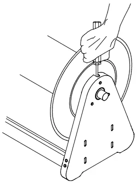
ADJUSTMENT PROCEDURES
Adjusting the reel
- Adjust reel drag by loosening or tightening set screw on hub casting on manual driven reel.
Hand crank to motor driven conversion
It is possible to convert a manual driven hose reel to a power or air driven type.
Contact Reelcraft customer service for information.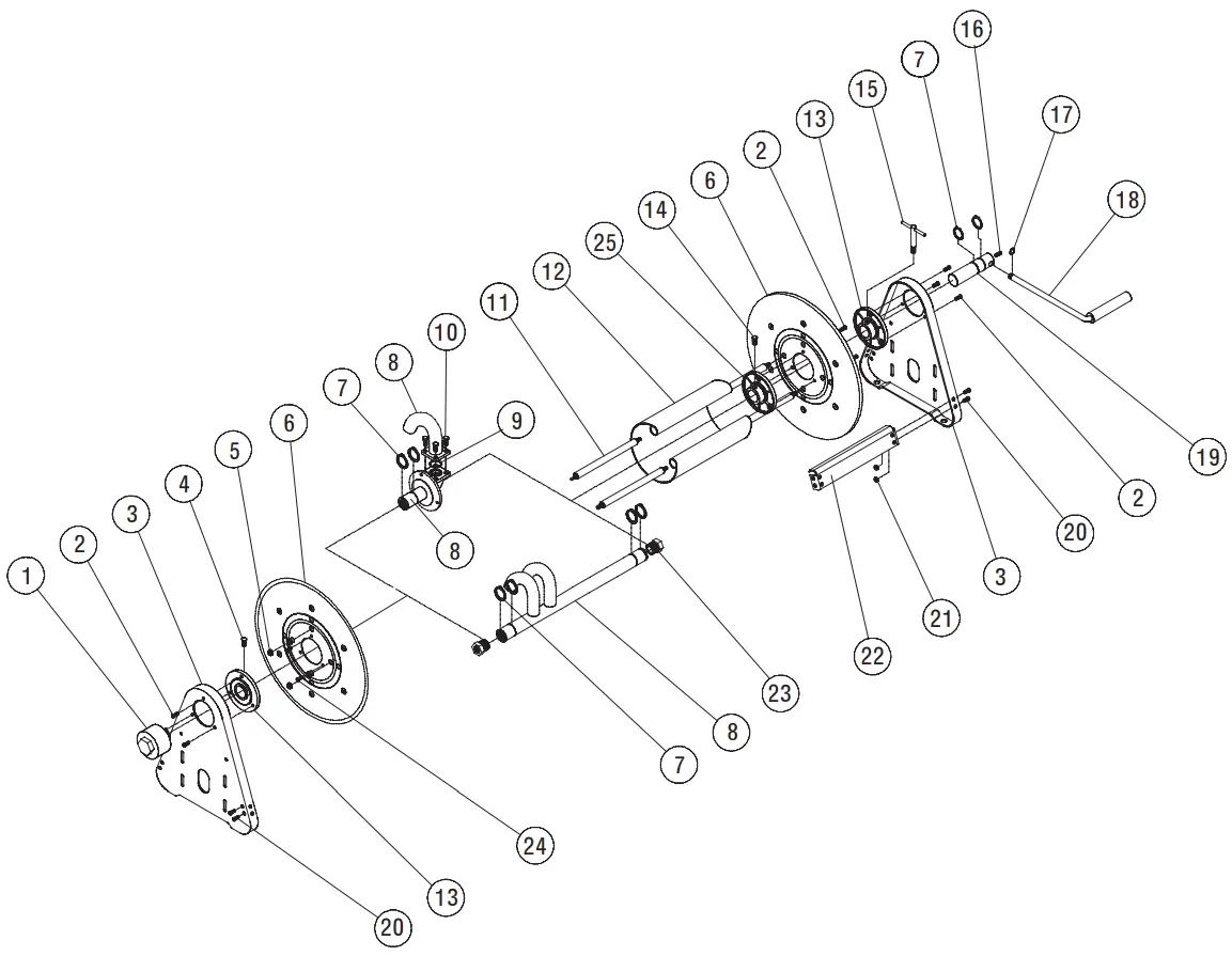
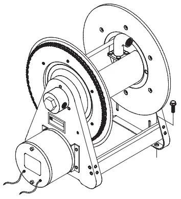
| ITEM | DESCRIPTION | QTY. | CA38106 M | CA38112 M | CA38118 M |
| 1 | Swivel assembly | 1 | S602033 | S602033 | S602033 |
| 2 | Screw, 5/16-12 x 5/8” | 9 | S317-31 | S317-31 | S317-31 |
| 3 | Side frame | 2 | 260403 | 260403 | 260403 |
| 4 | Set screw 3/8 brass | 1 | 300099 | 300099 | 300099 |
| 5 | Nut, 5/16-18 | 8 | S85-7 | S85-7 | S85-7 |
| 6 | Spool flange | 2 | S260399-3 | S260399-3 | S260399-3 |
| 7 | Snap ring | 3 | 300007 | 300007 | 300007 |
| 8 | Inlet assembly | 1 | 600327-1 | 600327-1 | 600327-1 |
| 9 | O-ring | 1 | S211-120 | S211-120 | S211-120 |
| 10 | Screw, 5/16-18 x 3/4” | 4 | S7-51 | S7-51 | S7-51 |
| 11 | Tie rod | 4 | 260402-100 | 260402-200 | 260402-300 |
| 12 | Spacer | 1 | 260401-1 | 260401-2 | 260401-3 |
| ITEM | DESCRIPTION | QTY. | CA38106 M | CA38112 M | CA38118 M |
| 13 | Hub & bushing assembly | 2 | S600640 | S600640 | S600640 |
| 14 | Set screw | 1 | 300006 | 300006 | 300006 |
| 15 | Lock handle assembly | 1 | S280109 | S280109 | S280109 |
| 16 | Set screw 3/8 square head | 1 | 300089 | 300089 | 300089 |
| 17 | Snap ring | 1 | S137-4 | S137-4 | S137-4 |
| 18 | Crank handle assembly | 1 | S600102 | S600102 | S600102 |
| 19 | Shaft & snap ring assembly | 1 | 602242 | 602242 | 602242 |
| 20 | Screw, 5/16-18 x 5/8” | 8 | S2-52 | S2-52 | S2-52 |
| 21 | Nut, 5/16-18 | 8 | 300107 | 300107 | 300107 |
| 22 | Cross brace | 2 | 263121-1 | 263121-2 | 263121-3 |
| 23 | Reducer bushing | — | None | None | None |
| 24 | Screw, 1/4-20 x 5/8” | 3 | S2-42 | S2-42 | S2-42 |
| 25 | Collar | 1 | 602688 | 602688 | 602688 |
Customer Service
Reelcraft Industries, Inc. • 2842 E Business Hwy 30, Columbia City, IN 46725
Ph: 800-444-3134 / 260-248-8188
Fax: 800-444-4587 / 260-248-2605
Customer Service: 855-634-9109
[email protected]
www.reelcraft.com