
MOUNTING INSTRUCTIONS


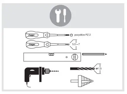
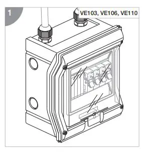
STEP 01
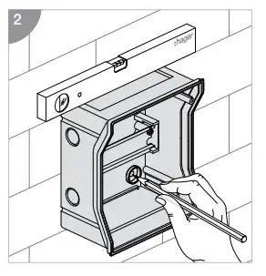
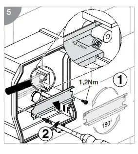
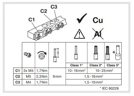
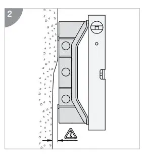
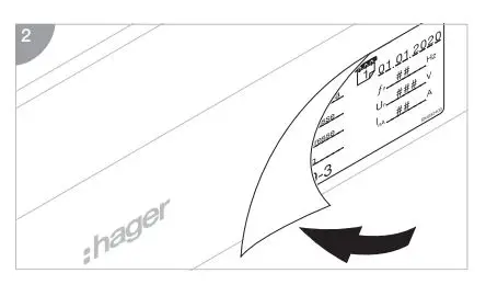
STEP 02
 Attention! Attention!It is critical that any enclosure is sized and selected to accommodate and dissipate heat rise generated from all installed devices. The table (right) provides maximum permissible heat dissipation for each golf enclosure size. Please ensure that you calculate internal heat generated from your installation and select the correct enclosure accordingly. |
| Reference | Admissible thermal dissipation loss for surface mounted distribution boards at temperatures rise ∆T* | ||||
| 10K W | 15K W | 20K W | 25K W | 30K W | |
| VE103.. | 2,4 | 4,0 | 5,7 | 7,5 | 9,4 |
| VE106.. | 3,2 | 5,3 | 7,6 | 10,1 | 12,6 |
| VE110.. | 4.5 | 7,4 | 10,6 | 10,0 | 17,6 |
| VE112.. | 7,7 | 12,8 | 18,3 | 24,2 | 30,3 |
| VE212.. | 9,5 | 15,7 | 23,5 | 29,7 | 37,3 |
| VE312.. | 11,3 | 18,8 | 26,8 | 35,4 | 44,4 |
| VE412.. | 13,2 | 21,8 | 31,2 | 41,2 | 51,7 |
| VE118.. | 9,9 | 16,4 | 23,5 | 31,0 | 38,9 |
| VE218.. | 12,3 | 20,4 | 29,2 | 38,6 | 48,4 |
| VE318.. | 14,8 | 24,6 | 35,2 | 46,4 | 58,2 |
*) ∆T is the temperature difference between the upper limiting temperature of the installed equipment and the ambient air temperature of the distribution board.
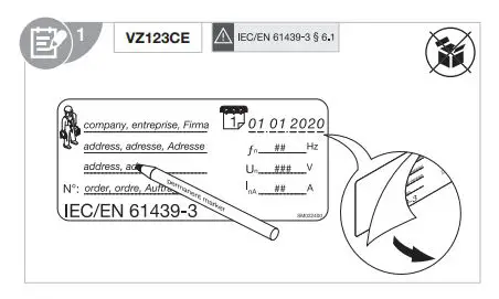
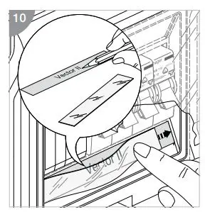
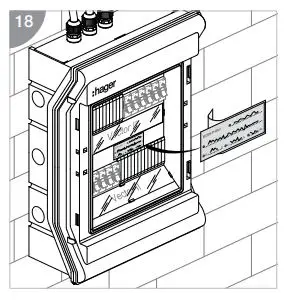
The Assembly (DBO) designated markings must be completed as specified in IEC/EN 61439 – 3 clause 6.1.
T +34 93 842 47 30
F +34 93 842 24 64
hager-02.2022


