![]() Cable Kit 200/500
Cable Kit 200/500
Cableflex 11
INSTALLATION INSTRUCTIONS
Skapa garantibevis direkt i mobilen
garantera.ebeco.se
Information requirements for electric local space heaters according to eco design, regulation (EU 2015/1188)
200 Cable Kit Cableflex 11

| Symbol | Value | Unit |
| Heat output | ||
| Nominal heat output | Pnom | See manual |
| Min. heat output (indicative) | Pmin | 0 kW |
| Max. continous heat output | Pmax, c | See manual |
| Auxiliary electricity consumption | Cable Kit 200 (EB-Therm 205) | |
| At nominell heat output | elmax | See manual |
| At min. heat output | elmin | 0,000 kW |
| In stand-by mode | elSB | 0,000 kW |
| Auxiliary electricity consumption | Cable Kit 500 (EB-Therm 500) | |
| At nominell heat output | elmax | See manual |
| At min. heat output | elmin | 0,000 kW |
| In stand-by mode | elSB | 0,000 kW |
| Cable Kit 200 (EB-Therm 205) | Cable Kit 500 (EB-Therm 500) | |
| Type of heat output/room temp. control (select one) | ||
| Single stage heat output and no room temp. control | NEJ No | NEJ No |
| Two or more manual stages, no room temp. control | NEJ No | NEJ No |
| With mechanic thermostat room temp. control | NEJ No | NEJ No |
| reglering With electronic room temp. control | NEJ No | NEJ No |
| reglering plus dygnstimer With electronic room temp. control plus day timer | NEJ No | NEJ No |
| reglering plus veckotimer With electronic room temp. control plus week timer | JA Yes | JA Yes |
| Other control options (multiple selections possible) | ||
| Room temp. control with presence detection | NEJ No | NEJ No |
| Room temp. control with open window detection | JA Yes | JA Yes |
| With distance control detection | NEJ No | JA Yes |
| With adaptive start control | JA Yes | JA Yes |
| With working time limitation (operating time limitaion) | NEJ No | JA Yes |
| With black bulb sensor | NEJ No | NEJ No |
Ecodesign
Information requirements for electric room heaters
In accordance with the ecodesign requirements for room heaters according to Regulation EU 2015/1188
| Designation | Value Unit | |
| Heat output | ||
| Nominal specified heat output | Pnom | See manual |
| Lowest heat output (indicative) | Pmin | 0 kW |
| Maximum continuous heat output | Pmax, c | See manual |
| Additive consumption | Cable Kit 200 (EB-Therm 205) | |
| At nominal specified heat output | elmax | See manual |
| At lowest heat output | elmin | 0.000 kW |
| In standby mode | elSB | 0.000 kW |
| Additive consumption | Cable Kit 500 (EB-Therm 500) | |
| At nominal specified heat output | elmax | See manual |
| At lowest heat output | elmin | 0.000 kW |
| In standby mode | elSB | 0.000 kW |
| Cable Kit 200 (EB-Therm 205) | Cable Kit 500 (EB-Therm 500) | |
| Type of heat output/room temperature control (select one) | ||
| One-step heat output without room temperature control | NO | NO |
| Two or more manual steps without room temperature control | NO | NO |
| With mechanical thermostat for room temperature control | NO | NO |
| With electronic room temperature control | NO | NO |
| With electronic room temperature control plus 24-hour timer | NO | NO |
| With electronic room temperature control plus weekly timer | YES | YES |
| Other control methods (several options can be selected) | ||
| Room temperature control with presence detection | NO | NO |
| Room temperature control with detection of open windows | YES | YES |
| With the possibility of remote control | NO | YES |
| With adjustable start control | YES | YES |
| With operating time limitation | NO | YES |
| With black body sensor | NO | NO |
Welcome!
Thank you for choosing Ebeco. We hope you will be happy with your underfloor heating system for many years to come.
For the guarantee to apply, the product must be installed and used as described in this manual. It is therefore important that you read the manual.
If you have any questions, please contact us at Ebeco.
Call 031-707 75 50 or send an email to [email protected]. You’ll find more information at ebeco.se.
 Important
The underfloor heating system is a high voltage system and must thus be installed according to applicable regulations by an authorised electrician. For the guarantee to apply, the guarantee certificate must be correctly and completely fillein, and signed by an authorised electrician. May only be installed indoors.
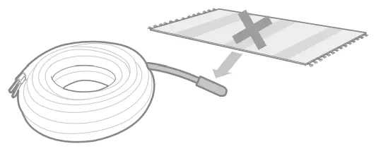
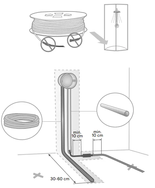
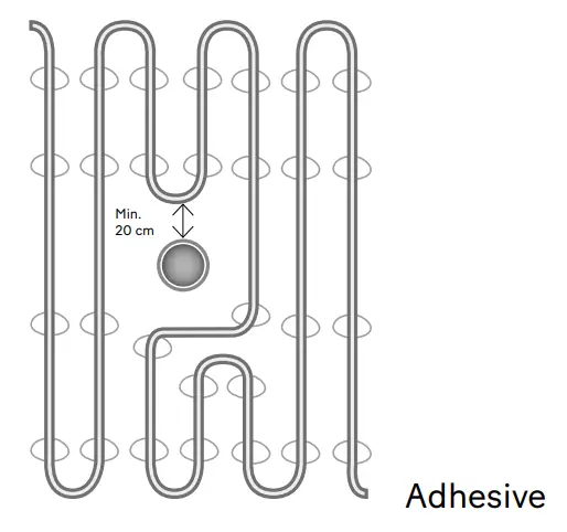
- The heating cable must not be cut. Furthermore, it may neither be crossed nor installed with spacing of less than 5 cm.
- The connection cable may be cut.
- The thermostat’s sensor cable may be cut.
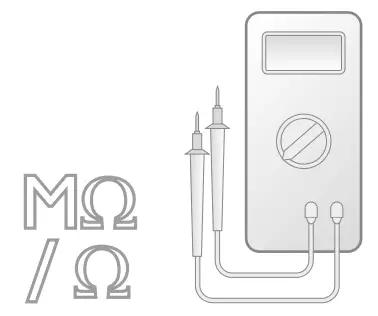
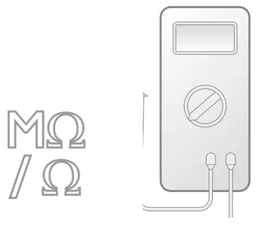
- The cable must be measured for resistance and insulation as per the instructions. Document the values in our web app, Garantera Ebeco, or in the guarantee certificate.
- Either a diagram or photo of the cable routing must be documented.
- The sign Heating Cable Installed must be posted at the main junction box.
- Heating must be regulated with Ebeco’s EB-Therm thermostats.
- The system must be connected to 230 V via a 30-mA earth fault circuit breaker.
- The heating cable must not be run under stationary furnishings, such as kitchen counters, closets, inner walls, etc. because this produces elevated temperatures.
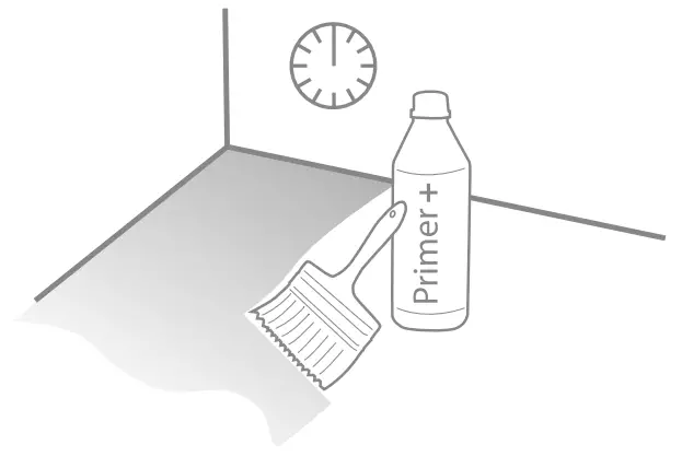
- In wet rooms, the heating cable must be run under a sealing layer.
- Wait 4 weeks after applying screed before turning on the heat.
This gives the screed time to dry properly. - In rooms with wooden floors the Room and floor thermostat function must always be used.
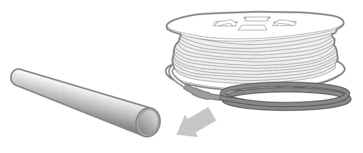
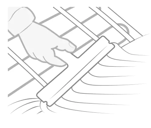
- When laying on reinforcement mesh, the cable must be laid on the top of the reinforcement mesh.
- The maximum permissible heat resistance of the floor material is 0.16 m² K/W.
Subflooring
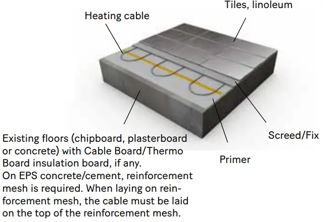
The heating cable is laid on floor constructions of concrete, plaster or chipboard and must then be screeded with a suitable levelling compound.
When applying screed on EPS concrete/cement, a reinforcement mesh is required in between as a spacer before the heating cable is laid.
On uninsulated concrete floors against the ground, additional insulation is always recommended. Also, that the heating is not switched off completely during the summer to counteract moisture rising.
Flooring materials
Cable Kit/Cableflex can be installed under tiles and natural stone floors, wood and laminate floors and linoleum.
When screeding, the heating cable must be laid in a minimum screed layer with a suitable levelling compound as follows:
Tile/natural stone floor 5 mm Wood/laminate flooring, 10 mm Linoleum 15 mm
See the applicable industry regulations for exact instructions regarding floor construction, screeding, sealing layers, tiling, jointing etc. Please contact your dealer for answers to specific questions.
Recommendations and Max. output depending on criteria and needs:
| Heating cable | Recommended output | |
| For screed | 11 W/m, c/c 7–15 cm | |
| Floor material | Regulation | Subflooring |
| Tile/natural stone Max 160 W/m² Max | Room/Floor | Concrete Max 160 W/m² |
| Wood/laminate/linoleum Max 75 W/m² | Room +floor | Combustible Max 120 W/m² In wooden subfloor Max 80 W/m² |
The output requirement of the room is governed by how well insulated it is, its air circulation and outdoor temperature.
Industry guidelines for wood/laminate and linoleum on underfloor heating
General conditions: The maximum permissible surface temperature is 27°C. This also applies under carpets and furniture.
Coverage:
Note that with all covering of wood/laminate and linoleum floors laid on underfloor heating, there is a risk:
- Of overtemperature in the floor
- That the temperature in the room becomes too low
Coverings include: carpets, beds without ventilated bases, bookshelves with fully-covering bottom, kitchen cabinets etc.
Specifications
Only on concrete subflooring
| Cable Kit 500 | Cable Kit 200 | Cableflex 11 | Output | Length | Nominal specified heating output | Max cont. heat output | AREA 75 W/m² | AREA 110 W/m² | AREA 140 W/m² | AREA 160 W/m² | Resistance* |
| 89 610 80 | 89 608 38 | 89 601 02 | 100 W | 8.9 m | 0.1 kW | 0.1 kW | 1.1 m² | 0.8 m² | 0.6 m² | 0.5 m² | 534 Ω |
| 89 610 81 | 89 608 50 | 89 601 04 | 150 W | 13.5 m | 0.15 kW | 0.15 kW | 2.0 m² | 1.35 m² | 1.1 m² | 0.9 m² | 350 Ω |
| 89 610 82 | 89 608 51 | 89 601 06 | 200 W | 18.5 m | 0.2 kW | 0.2 kW | 2.7 m² | 1.85 m | 1.5 m² | 1.3 m² | 260 Ω |
| 89 610 83 | 89 608 52 | 89 601 08 | 260 W | 23 m | 0.26 kW | 0.26 kW | 3.4 m² | 2.3 m² | 1.8 m² | 1.6 m² | 207 Ω |
| 89 610 84 | 89 608 53 | 89 601 10 | 330 W | 31 m | 0.33 kW | 0.33 kW | 4.4 m² | 3.1 m² | 2.3 m² | 2.1 m² | 161 Ω |
| 89 610 85 | 89 608 54 | 89 601 12 | 400 W | 37 m | 0.4 kW | 0.4 kW | 5.3 m² | 3.7 m² | 2.8 m² | 2.5 m² | 133 Ω |
| 89 610 86 | 89 608 55 | 89 601 14 | 470 W | 43 m | 0.47 kW | 0.47 kW | 6.3 m² | 4.3 m² | 3.4 m² | 3.0 m² | 112 Ω |
| 89 610 87 | 89 608 56 | 89 601 16 | 540 W | 49 m | 0.49 kW | 0.49 kW | 7.2 m² | 4.9 m² | 3.9 m² | 3.4 m² | 98 Ω |
| 89 610 88 | 89 608 57 | 89 601 18 | 650 W | 58 m | 0.65 kW | 0.65 kW | 8.7 m² | 5.8 m² | 4.7 m² | 4.1 m² | 81 Ω |
| 89 610 89 | 89 608 58 | 89 601 20 | 810 W | 73 m | 0.81 kW | 0.81 kW | 10.7 m² | 7.3 m² | 5.8 m² | 5.0 m² | 66 Ω |
| 89 610 90 | 89 608 59 | 89 601 22 | 960 W | 86 m | 0.96 kW | 0.96 kW | 12.8 m² | 8.6 m² | 6.9 m² | 6.0 m² | 55 Ω |
| 89 610 91 | 89 608 60 | 89 601 24 | 1180 W | 107 m | 1.18 kW | 1.18 kW | 16.05 m² | 10.7 m² | 8.4 m² | 7.4 m² | 45 Ω |
| 89 610 92 | 89 608 61 | 89 601 26 | 1380 W | 124 m | 1.38 kW | 1.38 kW | 18.3 m² | 12.4 m² | 9.8 m² | 8.6 m² | 38 Ω |
| 89 610 93 | 89 608 62 | 89 601 28 | 1710 W | 155 m | 1.71 kW | 1.71 kW | 22.7 m² | 15.5 m² | 12.2 m² | 10.7 m² | 31 Ω |
| 89 610 94 | 89 608 63 | 89 601 30 | 2080 W | 187 m | 2.08 kW | 2.08 kW | 27.7 m² | 18.7 m² | 14.9 m² | 13.0 m² | 25 Ω |
| Supplementary kit without thermostat for Cable Kit 500/200: | |||||||||||
| 89 608 90 | |||||||||||
| *Tolerance -5 % – +10 % | |||||||||||
| 1180 W | 107 m | 1.18 kW | 1.18 kW | 16.05 m² | 10.7 m² | 8.4 m² | 7.4 m² | 45 Ω | |||
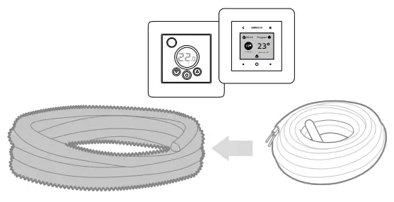
Materials and accessories
| Included in package: | CK 500 | CK 200 | Cableflex 11 |
| Underfloor heating cable (2.5 m connection cable) | X | X | X |
| Thermostat with sensor cable | X | X | |
| Spiral tube with adapter | X | X | |
| Adhesive sticks | X | X | |
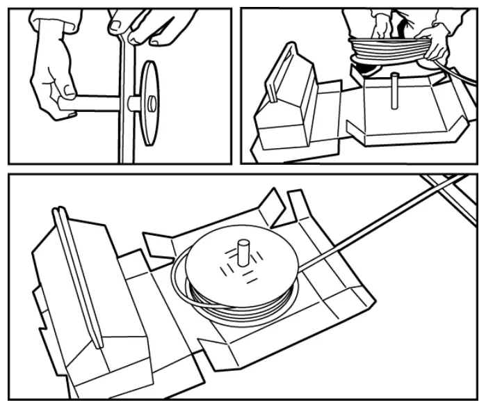
| Reel bracket | X | X | X |
| Sign Heating Cable Installed | X | X | X |
Accessories
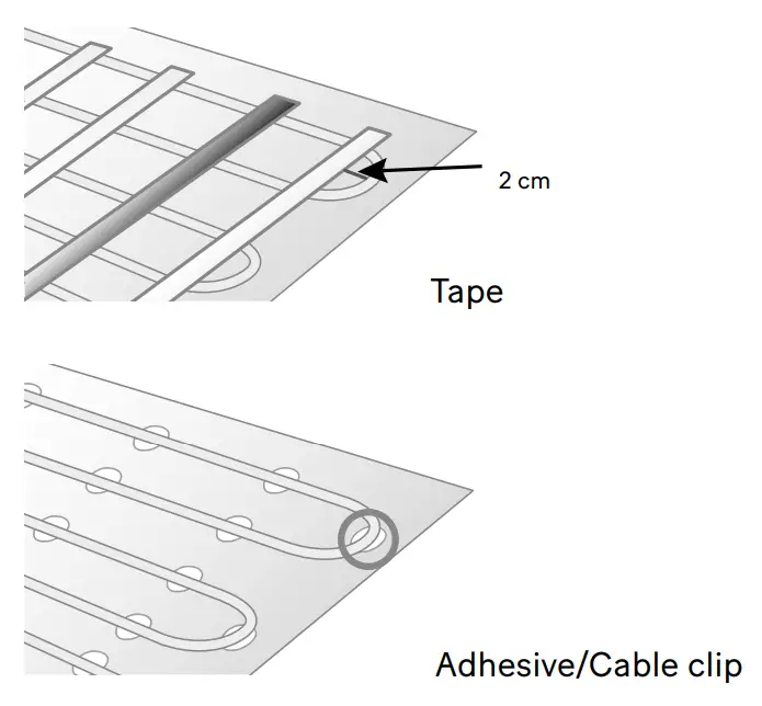
Cable Clip (89 609 58)
Cable Board (89 601 80)
Tape (89 353 49)
Sensor hose (89 605 41)
Adhesive sticks (16 939 93)
Compare with the contents in your kit. Check the label on the cable reel to ensure that you have received the correct cable length.
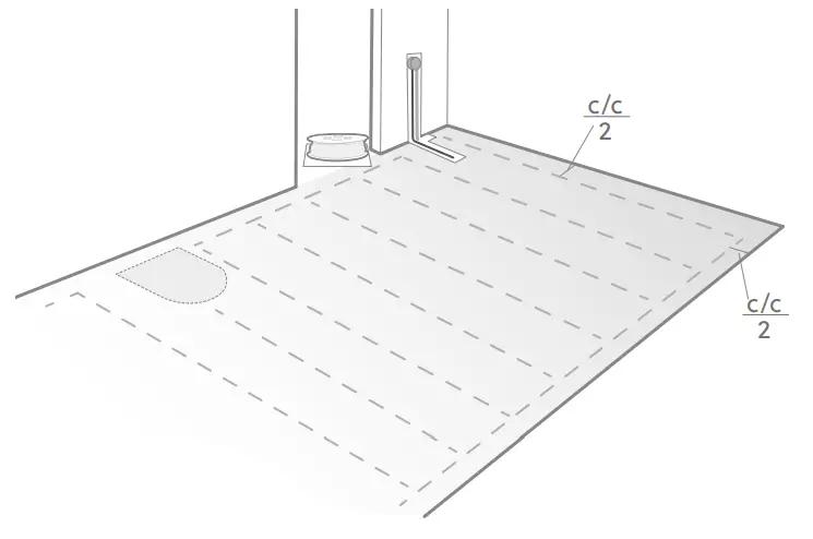
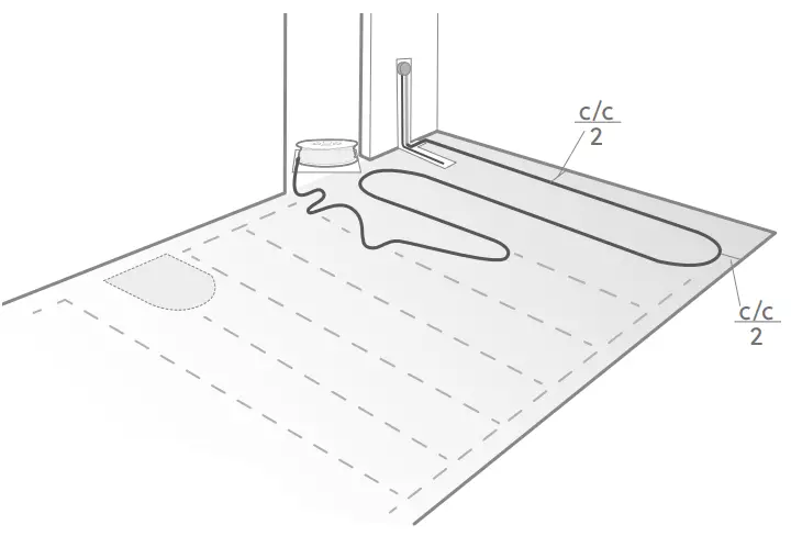
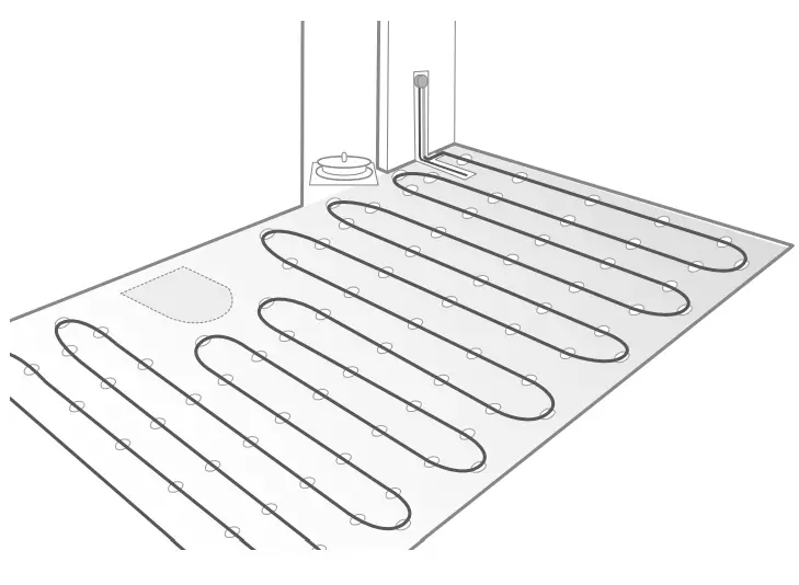
Plan the installation
Because the heating cable may neither be cut nor crossed, installation must be carefully planned so that the cable is correct for the room. Use the metre marking on the cable
after half the installation to make any adjustments to c/c distances and to avoid surplus heating cable once the calculated area has been covered.
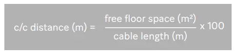
Calculate the c/c distance
Do as follows to find the exact c/c distance for cable laying. Calculate the room’s floor area. Subtract for fixed furnishings, such as cabinets and counters, so that you obtain the free floor area. Divide the free floor area by the