CTA Digital PAD-AFSVP VESA-Compatible Height-Adjustable Floor Stand
Contents: Instructions:
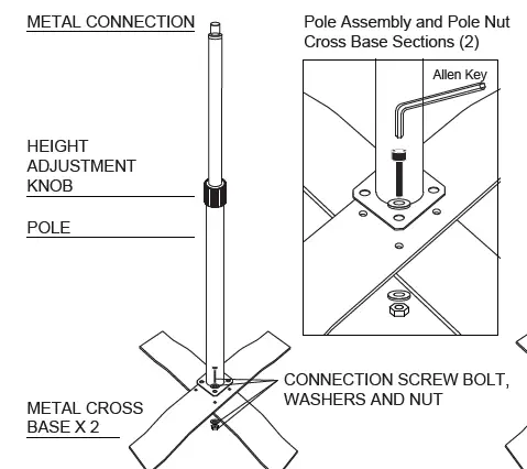
Base Assembly and Connecting the Metal Cover:
- Place the metal base pieces with the higher piece on top of the cross base. Align the holes at the bottom of the pole with the holes on the cross base.
- Insert a screw bolt with a washer into each of 4 holes. Place another washer on the underside of each screw bolts.
- Grip the nut on the underside with one hand, and use the other to tighten each screw with the Allen key. Repeat to tighten all four screw bolts.
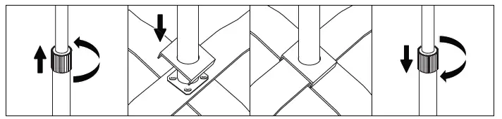
- Rotate the grip counterclockwise to loosen completely and remove from top of pole.
- Place the square metal cover over the top of the pole and slide down to stand base.
- Place grip back over stand pole and tighten.
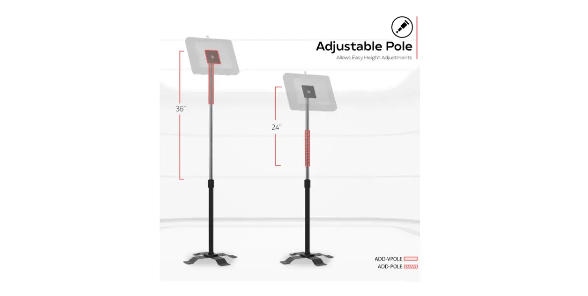
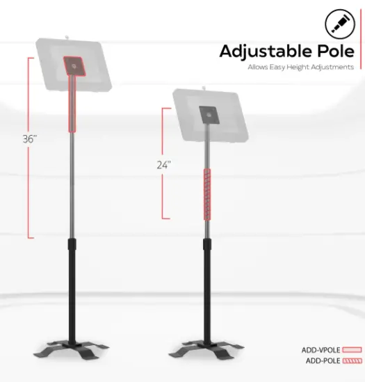
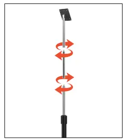
VESA Pole Assembly to Base:
Screw-in ADD-VPOLE and ADD-POLE as shown above.
Mounting Item to VESA plate:
Combine nuts and bolts through VESA plate from the front & back as shown with provided tools.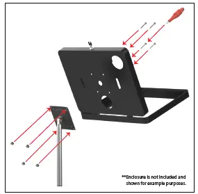
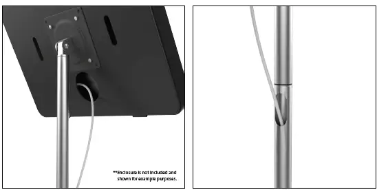
Cable Routing/Cable Management:
Route the cable through the hole at the top of the body and out the bottom.