![]()
FORCE MEASUREMENT SOLUTIONS
Installation & User Manual
9825
Info Icons Note: “Note” means essential information that will help you use the device more effectively.
![]() Caution: “Caution” means this may cause damage to your device or data loss if you do not follow the instructions.
Caution: “Caution” means this may cause damage to your device or data loss if you do not follow the instructions.![]() Warning: “Warning” means potential danger. Example: property damage, personal injury or even death.
Warning: “Warning” means potential danger. Example: property damage, personal injury or even death.
Pre Installation Warnings
![]() Warning: This device must be installed and connected by a professional electrical staff with the power supply disconnected for safe and dependable operation.
Warning: This device must be installed and connected by a professional electrical staff with the power supply disconnected for safe and dependable operation.![]() Warning: This device cannot be used in an unsafe environment. Example: Where explosion protection is required.
Warning: This device cannot be used in an unsafe environment. Example: Where explosion protection is required.
Unpacking & Installation
Unpacking: Please follow these inspection procedures after unpacking the product:
– Check the product to ensure that there was no damage in transit.
– Check the following list and confirm that all the items are in the carton:
– 9825 Digital Indicator
– External Connecting Terminals
– Clamping Strips & Anchor Nuts
– 9825 External Power Supply
– 9825 Grounding Cable Assembly
– 9825 Installation & User Manual
– Product Qualification Certificate
Storage & Installation:
The 9825 indicators must be stored in a dry, dust-free environment before use. Storage temperature is -20°C to +65°C (-4°F to +149°F), working environment temperature is -10°C to +104°F (+14°F to +104°F), and relative humidity no more than 95% (Non-Condensing).
The 9825 digital indicator uses panel installation, which requires the thickness of the cabinet’s front panel to be no more than 4mm. Before installation, remove the two mounting screws from the indicator’s clamping strips, then remove the clamping strips. Push the indicator into the opening on the cabinet, then reinsert the clamping strips. Gently tighten the two mounting screws. Indicator structure and physical dimensions (mm) 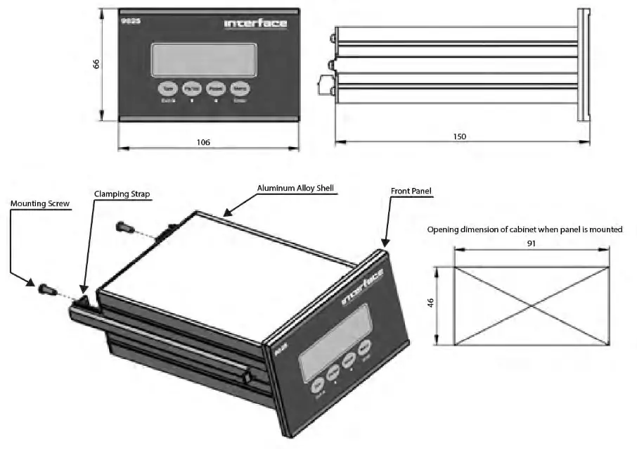
Interface Inc. www.interfaceforce.com
Connections:
Power Connections:
The 9825 has an input range of 9VDC to 36VDC. The maximum electrical power consumption of the 9825 is 6W (8W Peak).The unit is shipped with an external 24VDC linear power supply and a grounding cable assembly. The GND Terminal should be routed to the grounding lug on the rear of the 9825 housing and then to earth using the provided grounding cable assembly in order to optimize signal stability.
Use the screw-down terminals to secure the power supply leads and grounding cable to the 3-position connector in the following configuration:
Pin Assignment:
1 = VDC +
2 = VDC 3 =
GND![]() Warning:
Warning:
Verify that the power supply connections are correct before powering on.![]() Note: Make sure that the power cord does not pose a potential obstacle or tripping hazard. Only use approved accessories and peripherals.
Note: Make sure that the power cord does not pose a potential obstacle or tripping hazard. Only use approved accessories and peripherals.
Load Cell Connections: The 9825 indicator uses a 6-wire load cell signal connection. This indicator provides a 4.5 volt DC excitation voltage to the load cell(s). The voltage difference between +SIG and -SIG is about 0 ~ 9mV when connected to a load cell with a 2mV/V output, and about 0 ~ 13.5mV when connected to a load cell with a 3mV/V output. The 9825 indicators can drive up to six (6) 350-ohm load cells (or the equivalent resistance of all load cells connected in parallel is higher than 87Ω).
If the application requires the 9825 to be connected to multiple load cells, please use a junction box.![]() Note: This product does not contain a junction box. If a junction box is necessary for your application, we recommend Interface Model JB104SS as an approved accessory.
Note: This product does not contain a junction box. If a junction box is necessary for your application, we recommend Interface Model JB104SS as an approved accessory.
The load cell cable requires a shield which must be properly grounded to ensure maximum stability. High quality cable is recommended. Be sure to route the load cell cable away
from high voltage/power cables. The maximum length allowed for the load cell or junction box cable is shown in the following table:
| 24 AWG | 20 AWG | 16 AWG | |
| Connect to 1-35011 load cell | 200 m | 300 m | 400 m |
| Connect to 3-35011 load cells | 60 m | 150 m | 200 m |
| Connect to 4-35011 load cells | 40 m | 100 m | 120 m |
Sensor Input Terminal Pin Assignment:
| Wire Name | Port Number | Definition | Voltage Range |
| + EXC | 1 | Positive excitation | 4.5V |
| + SEN | 2 | Positive sense | 4.5V (after connecting to a load cell) |
| + SIG | 3 | Positive signal | Slightly higher than 2.25V (after connecting to a load cell) |
| SOLD | 4 | Shield ground | NA |
| – SIG | 5 | Negative signal | Slightly lower than 2.25V (after connecting to a load cell) |
| – SEN | 6 | Negative sense | OV (after connecting with a load cell) |
| – EXEC | 7 | Negative excitation | OV |
Four-Wire Analog (Load Cell) or (Junction Box) Connection: 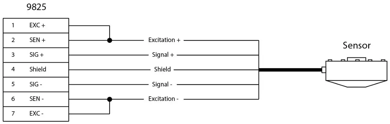 Six-Wire Analog (Load Cell) or (Junction Box) Connection:
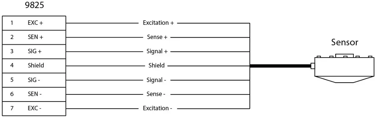
Serial I/O Device Connections:
The 9825 indicator comes standard with one USB port.
USB Port Connections:
The 9825 indicator comes standard with a MINI-USB port that can be connected to a PC.
This USB port is designed for data communication and firmware upgrades.
Analog Output Connections:
Use the JP1 pin header on the internal analog option board to configure the analog output for current output (4-20mA, 0-24mA) or voltage output (0-10V, 0-5V). Please note that voltage and current outputs cannot be used at the same time. We suggest using a PLC or PC to monitor the analog output calibration.
Configure the voltage or current output as follows. Output type is selected in the Analog Out Setup menu, under the Output Type submenu.
Voltage output: Select either 0-5V or 0-10V. Use the Analog + & Analog – terminals.
Current output: Select either 0-24mA or 4-20mA. Use the Analog + & Analog – terminals.
Relay Input/Output Control Connections:
The Output Connections:
The 9825 optional I/O control port is relay-based and can be used with an AC or DC power supply. The DC power supply range is 24VDC to 100VDC. The AC power supply
range is up to 220VAC. The COM terminal can be connected to the positive or negative of the power supply. The maximum power output of each relay is 90W / 5A.
Output control interfaces and load connection diagram: 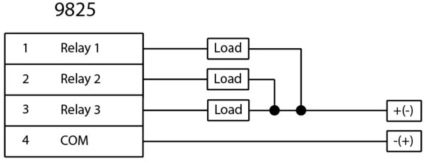
Output control interfaces and PLC connection diagram: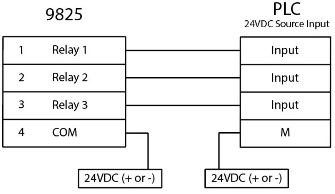
The Input Connections: The input interfaces are isolated, passive inputs. The interfaces can be connected to many control control keys (Buttons), and the wiring is as follows.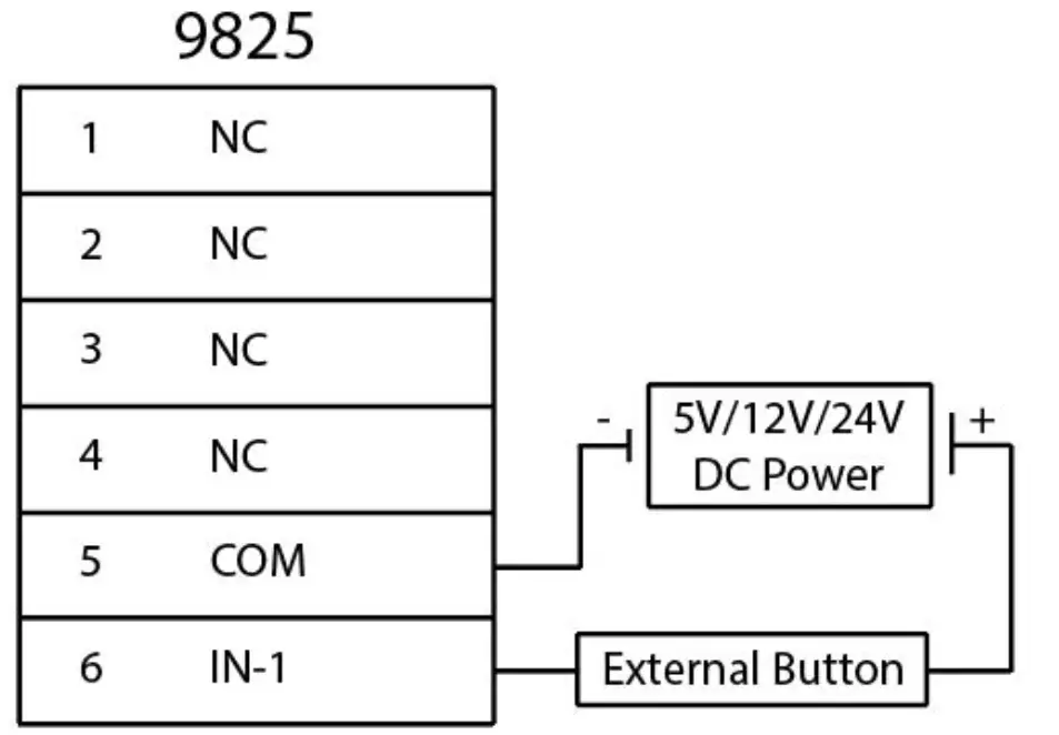
Basic Operation
Power On: The display will show the Interface logo followed by the Device Mode and Firmware Version. After that, the current force value will be displayed.
Display Details: The 9825 utilizes a 128 x 32 dot OLED display with adjustable LED back-light. The table below summarizes the display annunciators.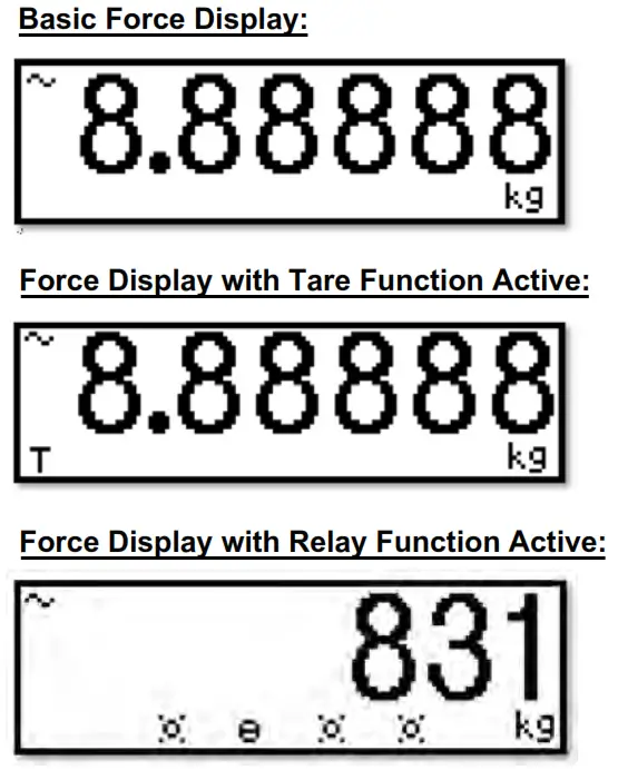
| Symbol | Display |
| T | Indicates that a push-button tare load has been established in the system |
| lb | Indicates that the unit of the displayed load is in pounds |
| kg | Indicates that the unit of the displayed load is in kilograms |
| This light is on whenever the measurement is unstable. | |
 | Status #1 active for selected Relay mode. Please refer to “I/O control interface and function” section |
 | Status #2 active for selected Relay mode. Please refer to “I/O control interface and function” section |
Keypad Details: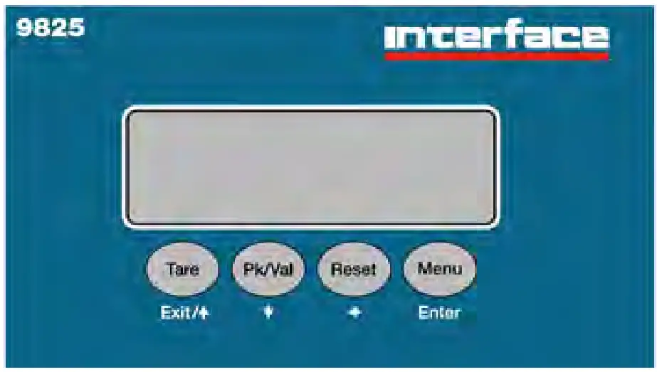
Keypad Functions:
Tare (Exit, ↑ ):
- When in display mode (Tare Function)
- Pressing this key sets force value to zero (sets tare).
- If tare is already set, pressing this key removes tare.
When in the setup menu (Exit Function)
- Return to a previous menu.
- Increase the value when used as a directional key ( ↑ ).
- Hold to exit the setup menu.
PK/Val ( ↓ ):
- When in display mode (PK/Val Function)
- Cycle among real-time, peak and valley display modes.
When in the setup menu ( ↓ Function)
- Enter sub-menu.
- Decrease a value when used as a directional key ( ↓ ).
Reset ( ← ):
- When in display mode (Reset Function)
- Resets peak and valley values.
When in the setup menu ( ← Function)
- Moves left when used as a directional key.
Menu (Enter):
- When in display mode (Menu Function)
- Hold this key until the buzzer sounds to enter the setup menu.
- When in the setup menu (Enter Function)
- Saves the current setting.
System Configuration
![]() Warning:
Warning:
Do not access the Advanced Menu unless instructed to do so by a qualified technician.
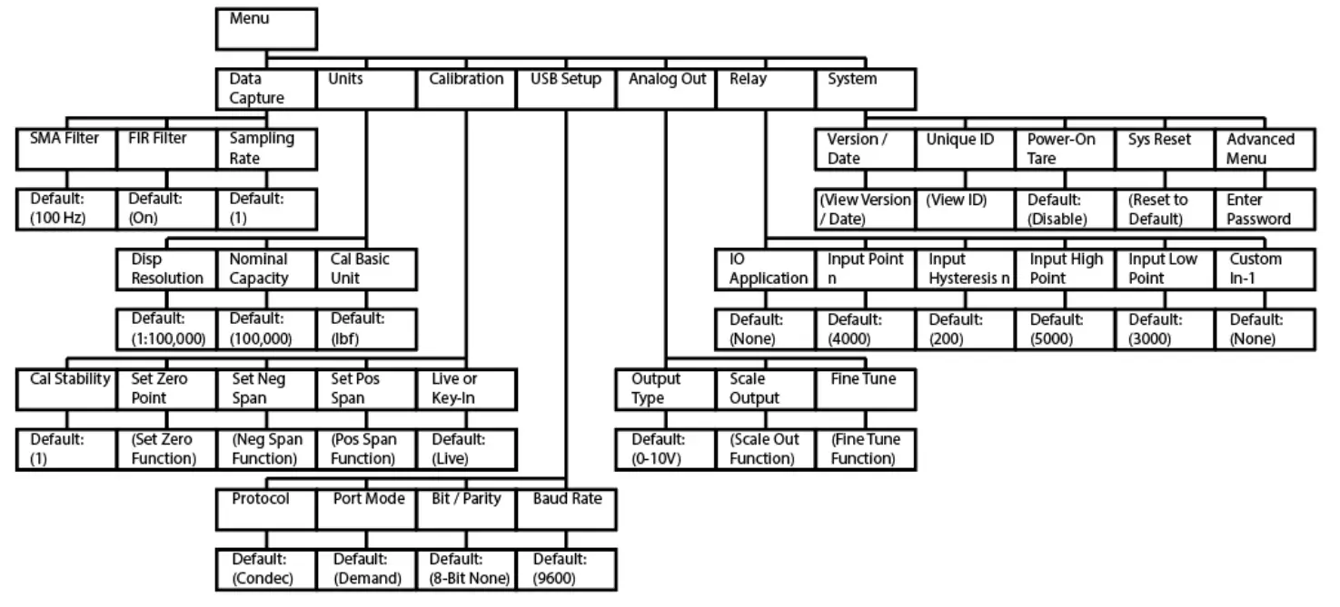
Menu Description:
| Menu | Sub-Menu | Description | Default | Options |
| Data Capture | Sampling Rate | Number of Samples per second. | 100Hz | 30, 40, 50, 60, 75, 80, 100, 120, 150, 170, 200, 240, 300, 400, 600, 1200Hz |
| FIR Filter (Finite Impulse Response) | Reduces the influence of nearby electrical or echanical noise sources. | On | Off, On | |
| SMA Filter (Simple Moving Average) | Smooths signal by averaging samples over a given span. | 1 | Integer values from 1 to 100 | |
| Units | Cal Basic Unit | Select engineering units displayed | lbf | lbf, ozf, N, kN, g, kg, UNIT_NONE |
| Nominal Capacity | Sets display output range | 100,000 | Integer values from 1 to 100,000 | |
| Disp Resolution | Set decimal placement and increments | 1:100,000 | Menu options are based on Nominal Capacity value |
| Calibration | Live or Key-In | Set calibration type | Live | Live, Key-In |
| Set Pos Span | Set span from zero to positive capacity | Press ↓ and enter to start sequence Fixture Press ↓ to start sequence | ||
| Set Neg Span | Set span from zero to negative capacity | |||
| Set Zero Point | Set zero | |||
| Cal Stability | A greater value can produce higher accuracy calibration points but will require a more stable mV/V input signal during calibration as well. | 1 | Integer values from 0 to 320 represent the number of samples averaged when capturing a calibration point. Larger values = greater stability required | |
| USB Setup | Baud Rate | Serial communication rate in bits per second | 9600 | 2400, 4800, 9600, 19200, 38400, 57600,115200 |
| Bit / Parity | Set Binary format and check bit | 8-bit None | 8-bit None, 8-bit Even, 7-bit Even, 7-bit Odd | |
| Port Mode | Set port mode | Demand | Demand, Continuous | |
| Protocol | Set Protocol (see protocol descriptions in the appendix) | Condec | Condec, ASCII | |
| Analog Out | Output Type | Set Analog output type | 0-10V | 4-20mA, 0-10V, 0-5V, 0-24mA |
| Scale Output | Adjust Low and High points using keypad | |||
| Fine Tune | Adjust 0%, 50%, 100% output points using keypad | |||
| Relay | IO Application | None | None, Setpoint, Alarm | |
| Input Pointn(Setpoint) | 4000 | Adjust values using keypad | ||
| Input Hysteresisn (Setpoint) | 200 | |||
| Input High Point (Alarm) | 5000 | |||
| Input Low Point (Alarm) | 3000 | |||
| Custom In-1 | None | None, Reset Key, Tare Key, Print Key | ||
| System | Version / Date | Display firmware version and date | Press ↓ to view | |
| Unique ID | Display Unique ID | |||
| Power-On Tare | Disable | Off, On | ||
| Sys Reset | Reset to default settings. | Press ↓ to execute | ||
| Advanced Menu | Password Required | Enter Password 336699 to access the Advanced Menu |
Calibration Procedures:
Calibration Overview:
The 9825 Indicator can be calibrated by using either a Live calibration method or a Key-In calibration method. It is important to set the Nominal Capacity Value before beginning calibration.
Live Calibration:
The Live calibration method produces the best possible system accuracy. This method requires one of the following:
– The load cell being paired with the 9825 Indicator will be connected to the instrument while a series of nominal force loads are applied to calibrate the instrument.
– A load simulator will be connected to the 9825 Indicator while a series of simulated mV/V loads are applied to calibrate the instrument.
Live calibration is accomplished by setting the Positive Span, Negative Span and Zero.
To execute a Live calibration, follow the steps below:
- Press and hold the Menu button to enter the setup menu. A beep will sound as the setup menu is activated.
- Using the → (Menu) button, scroll until Calibration is displayed on the screen. Press the ↓ (Pk/Val) button to enter the calibration sub-menus.
- Using the → (Menu) button, scroll until Set Pos (or Neg) Span is displayed on the screen. Press the ↓ (Pk/Val) button to initiate the calibration process.
- The term Fixture will show on the screen. At this point the load cell should be set into its fixturing, but with no additional calibra,tion loads applied. If a simulator is being
used for the Live calibration, connect the simulator, but set its value to 0mV/V. Press the Menu (Enter) button to save this point. - After the Fixture value has been set, the term C1 (calibration point #1) will appear on the screen. The user should set the numerical field so that it displays the nominal
force load that is about to be applied. Once this value has been input and the applied force load has stablized, pressing the Menu (Enter) button will capture this point. - The C2 term will then appear. If the user would like to add another calibration point (up to six are possible) they can repeat the actions in Step 5. If the user would like to
end the calibration, they should leave the numerical field as 0 and press the Menu (Enter) button.
![]() Note: if the calibration was unsuccessful, an error message will appear:
Note: if the calibration was unsuccessful, an error message will appear:
– “Err2” : There is not enough signal from the load cell. This is most commonly caused by incorrect wiring or a damaged load cell.
Repeat this process in the opposing polarity, than proceed to Zero calibration.
Zero Calibration:
- Press and hold the Menu button to enter the setup menu. A beep will sound as the setup menu is activated.
- Using the → (Menu) button, scroll until Calibration is displayed on the screen. Press the ↓ (Pk/Val) button to enter the calibration sub-menus.
- Using the → (Menu) button, scroll until Set Zero Point is displayed on the screen.
- At this point, the Zero Calibration is ready to begin. Be sure the load cell is connected and in an unloaded state. If using a simulator, be sure that the simulator is set to 0mV/V. Press the ↓ (Pk/Val) button to initiate the Zero Calibration. Dashed lines will be displayed at the bottom right of the screen to indicate that the 9825 is capturing the zero point.
Key-In Calibration:
The Key-In calibration method is typically only used in emergency cases when the indicator cannot receive a Live calibration. The Key-In method uses a single point to
establish the span of the load cell. It ignores load cell nonlinearity and any asymmetry between the opposing loading modes.
To execute a Key-In calibration, follow the steps below:
- Press and hold the Menu button to enter the setup menu. A beep will sound as the setup menu is activated.
- Using the → (Menu) button, scroll until Calibration is displayed on the screen. Press the ↓ (Pk/Val) button to enter the calibration sub-menus.
- The Live or Key-In sub-menu is the first Calibration sub-menu and should be displayed on the screen. Press the ← (Reset) button to change the flashing value from Live to Key-In. Press the Menu (Enter) button to save this setting.
- Press the → (Menu) button to change the sub-menu to Rated Output. Press the ↓ (Pk/Val) button to enter the Rated Output sub-menu.
- Enter the sensitivity of the load cell into the numerical field. This is typically the mV/V output of the load cell at its rated capacity. Press the Menu (Enter) button to save this value.
- Press the → (Menu) button to change the sub-menu to Sensor Capacity. Press the ↓ (Pk/Val) button to enter the Sensor Capacity sub-menu.
- Enter the rated capacity of the load cell into the numerical field. Press the Menu (Enter) button to save this value.
- Press the → (Menu) button to change the sub-menu to Set Zero Point. User should preform a Zero Calibration as detailed above.
Industrial Interfaces
USB Interface Communication:
The 9825 indicator can connect to a PC via USB cable. First a USB driver must be installed on the PC to access the 9825. Measurement data can be accessed by using a terminal emulation application such as HyperTerminal. The USB Port output has Two fixed strings: ASCII and Condec.
Analog Output Interface:
Analog Output Calibration:
The mode of the Analog Output can be selected from its Output Type sub-menu. There are four modes of analog output: 4-20mA, 0-24mA, 0-5V and 0-10V. Please refer to the wiring section for the proper jumper setting of the optional analog output board. To calibrate the Analog Output, follow the steps below:
Scale Output:
- While within the Analog Output menu, scroll to Scale Output and press the ↓ (Pk/Val) button to initiate the Scale Output sequence.
- Scale Output is set by inputting a Low and High force value. To set a given value, use the numerical field on the screen to input the desired force. The first character can be used to switch the sign convention from + to – and back. Press the ↓ (Pk/Val) button to save the setting.
Fine Tune:
Before performing this part of the device setup, the Analog Output of the 9825 should be connected to whatever instrument will be accepting and measuring the analog signal.
- In the Analog Output setup menu, scroll to Fine Tune and press the ↓ (Pk/Val) button to initiate the Fine Tune sequence.
- The screen will display “0%”, which indicates the lowest point of the analog scale. For voltage outputs, this is 0VDC. For current outputs this is either 0mA (0-24mA) or 4mA (4-20mA).
- By adjusting the numerical value on the screen, the Analog output will be Fine Tuned.
The digit furthest to the left creates the greatest change in output, while the digit furthest to the right creates the smallest change in output. Adjust this number until the measured value on the connected meter or PLC shows the minimum point on the analog scale.
Press Menu (Enter) to save this value and proceed. - Repeat this process for the 50% point. For a 0-5V setting, the output will be 2.5V. For a 4-20mA setting, the output will be 12mA and so on.
- Repeat this process for the 100% point.
![]() Notes:
Notes:
– The analog output mode setup to 4mA-20mA: If the load 0kg, the voltage output is 0. If the load is the full range of the scale than the voltage output is 24mA.
– The analog output mode setup to 0-10V: If the load 0kg, the voltage output is 0. If the load is the full range of the scale than the voltage output is 10.8V.
I/O Control Applications:
SetPoint Application:
The following conditions should occur when you use SetPoint application:
- When the load is less than the value of “Input Point 1”:
– The symbol will show on the display.
– The OUT-1 relay will close.
Otherwise, the symbol will show on the display and the OUT-1 relay will open.
 - When the load is less than the value of “Input Point 2”, But greater than the value of “Input Point1”:
– The symbol will show on the display.
– The OUT-2 relay will close.
Otherwise, the symbol will show on the display and the OUT-2 relay will open. - When the load is less than the value of “Input Point 3”, but greater than the value of “Input Point2”:
– The symbol will show on the display.
– The OUT-3 relay will close.
Otherwise, thesymbol will show on the display and the OUT-3 relay will open. - When the load is less than the value of “Input Point 4”, but greater than the value of “Input Point 3”:
– The symbol will show on the display.
– The OUT-4 relay will close.
Otherwise, thesymbol will show on the display and the OUT-4 relay will open.
Alarm Application:
Loads of the four configurable Alarm points must follow this formula:
Input ExtraHigh > Input HighPoint > Input LowPoint > Input ExtraLow
- When the load is less than the value of “Input ExtraHigh”:
– The symbol will show on the display
– The alarm will sound
– The OUT-1 relay will close
– The display will send a warning message
Otherwise, thesymbol will show on the display and the OUT-1 relay will open. - When the load is less than the value of “Input ExtraHigh”, but greater than the value of “Input HighPoint”:
– The symbol will show on the display
– The alarm will sound
– The OUT-2 relay will close
– The display will send a warning message
Otherwise, thesymbol will show on the display and the OUT-2 relay will open. - When the load is less than the value of “Input LowPoint”, but greater than the value of “Input ExtraLow”:
– Thesymbol will show on the display
– The alarm will sound
– The OUT-3 relay will close
– The display will send a warning message
Otherwise, the symbol will show on the display and the OUT-3 relay will open. - When the load is less than the value of “Input ExtraLow”:
– Thesymbol will show on the display
– The alarm will sound
– The OUT-4 relay will close
– The display will send a warning message
Otherwise, thesymbol will show on the display and the OUT-4 relay will open.
Indicator Info
Software Version:
This Information can be accessed from the main menu under Menu_System_Version/Date.
– Software Version:
– Last Update: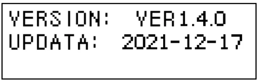
Appendix
Appendix 1: Command Output Format 1 – Continuous Mode (ASCII)
In this mode of communication, the indicator transmits the data frame continuously. The load value in the frame is expressed in ASCII.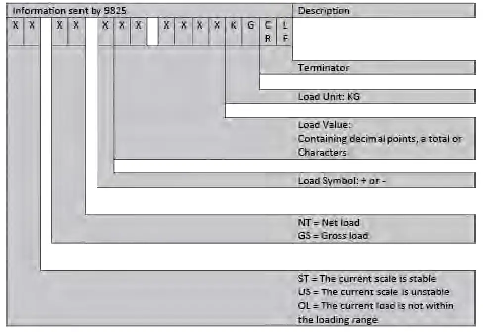
Appendix 2: Command Output Format 1 – Demand Mode (ASCII)
This host device (PC) will output the demand commands through the serial ports when the scale is in the normal loading status.
The demand command format is shown below:
| R | E | A | D | CR | LF |
| (0x52) | (0x45) | (0x41) | (0x44) | (0x0D) | (0x0A) |
The serial output data format is as follows: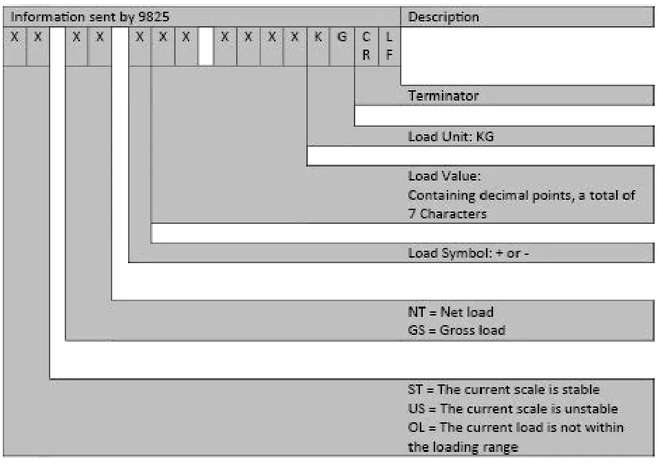
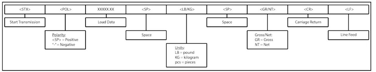
Appendix 3: Codec Format Output (Codec)
Codec Demand Output:
 Demand Commands:
“P” > Print
“T” > Tare
“Z” > Zero
“G” > Gross
“N” > Net
Condec Continuous Output: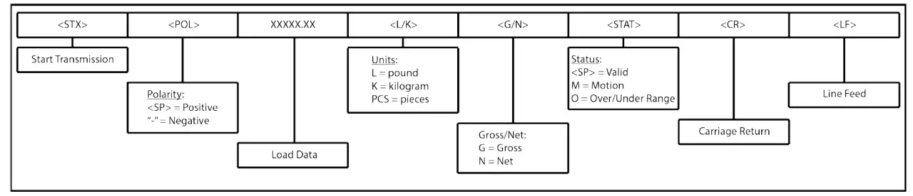
| Function Address | Description | |
| 40001 | Reads the instrument gross value | |
| 40002 | Reads the instrument tare value | |
| 40004 | Bit 0 | Reads the instrument status word |
| 0: Plus sign 1: Minus sign | ||
| Bit 1 | 0: Unstable 1: Stable | |
| Bit 2 | 0: Normal 1: Overflow | |
| Bit 3 | Decimal point: 010 = 0; 011 = 0.0; 100 = 0.00; 101 111 = 0; | |
| Bit 4 | ||
| Bits | ||
| Bit 6 “.. 9 | Undefined | |
| Bit 10 | 0 = lb 1 = kg | |
| Bit 11 “. | Undefined | |
Function Address | Description | ||
| 40003
| Bit 0 | Write 1= tare the scale | |
| Bit 1 | Write 1 = clear the scale | ||
| Bit 2 | Write 1= zero the scale | ||
| Bit 3 –7 | Unidentified | ||
![]() Note: The starting address 40001 of MODBUS is not suitable for SIEMENS soft.
Note: The starting address 40001 of MODBUS is not suitable for SIEMENS soft.
Specifications
EXCITATION | ||
| Excitation Voltage – VDC | 4.5 | |
| Current – mA | 100 | |
PERFORMANCE | ||
| Maximum Display Counts | ±999,999 | |
| Internal Resolution Counts | 1,000,000 | |
| Signal Input Range – mV/V | ±4.5 | |
| Sensitivity – μV/count | 0.03 | |
| Readings Per Second – MAX | 1000 | |
| Filter Settings | Off, Static, Dynamic FIR and/or Moving Average | |
| Serial Interfaces | USB 2.0 standard | |
ENVIRONMENTAL | ||
| Operating Temperature | °C | -10 to +45 |
| °F | +14 to 113 | |
| Relative Humidity – % MAX | at °C | 10% to 90%, non-condensing |
| at °F | 10% to 90%, non-condensing | |
POWER | ||
| Supply | VDC | 24 VDC with supplied 120V 60Hz, AC/ DC adapter or 9-36 VDC external supply |
| Power Consumption | W | 6 RMS, 8 Peak |
| Switching frequency of internal PSU | 300kHz | |
| Provides isolation | 6kV | |
MECHANICAL | ||
| Dimensions – W x H x D | mm | 106 x 66 x 150 |
| in | 4.17 x 2.6 x 5.91 | |
| Weight | g | 68 |
| lbs | 1.5 | |
Display – mm(in) | 128 x 32 OLED dot matrix display. Font size is 9.5 (0.37) H and 6.5 (0.26) W | |
Panel Cutout – W x H | mm | 91 x 46 |
| in | 3.58 x 1.81 | |
FAST ANALOG OUTPUT – kHz | VDC 0-5, 0-10, 2.5+/-2.5, 5+/-5 mA 4-20, 0-24, 12+/-8, 12 +/-12 | |
Warranty
Warranty All indicator products from Interface Inc., (‘Interface’) are warranted against defective material and workmanship for a period of (1) one year from the date of dispatch. If the ‘Interface’ product you purchase appears to have a defect in material or workmanship or fails during normal use within the period, please contact your Distributor, who will assist you in resolving the problem. If it is necessary to return the product to ‘Interface’ please include a note stating name, company, address, phone number and a detailed description of the problem. Also, please indicate if it is a warranty repair. The sender is responsible for shipping charges, freight insurance and proper packaging to prevent breakage in transit. ‘Interface’ warranty does not apply to defects resulting from action of the buyer such as mishandling, improper interfacing, operation outside of design limits, improper repair or unauthorized modification. No other warranties are expressed or implied. ‘Interface’ specifically disclaims any implied warranties of merchantability or fitness for specific purposes. The remedies outlined above are the buyer’s only remedies. ‘Interface’ will not be liable for direct, indirect, special, incidental or consequential damages whether based on the contract, tort or other legal theory. Any corrective maintenance required after the warranty period should be performed by ‘Interface’ approved personnel only


