Shinko JIR-301-M Multi Range Digital Indicator Instruction Manual

INSTRUCTION MANUAL
SHINKO TECHNOS CO., LTD. Head office: 2-5-1, Senbahigashi, Minoo, Osaka, 562-0035, Japan
TEL: +81-72-727-6100 FAX: +81-72-727-7006 URL: https://shinko-technos.co.jp/e/ E-mail: [email protected]
For detailed usage, refer to the Instruction Manual for the JIR-301-M. Please download the full Instruction Manual from the Shinko Technos website.
https://shinko-technos.co.jp/e/ Support & Downloads Downloads Manuals
Thank you for purchasing our JIR-301-M, Digital Indicator. This manual contains instructions for the mounting, functions, operations and notes when operating the JIR-301-M. To ensure safe and correct use, thoroughly read and understand this manual before using this instrument. To prevent accidents arising from the misuse of this instrument, please ensure the operator receives this manual.
Safety Precautions (Be sure to read these precautions before using our products.)
The safety precautions are classified into 2 categories: “Warning” and “Caution”. Warning: Procedures which may lead to dangerous conditions and cause death or serious injury, if not carried out properly.Caution: Procedures which may lead to dangerous conditions and cause superficial to medium injury or physical damage or may degrade or damage the product, if not carried out properly.
 Warning
- To prevent an electric shock or fire, only Shinko or other qualified service personnel may handle the inner assembly.
- To prevent an electric shock, fire or damage to the instrument, parts replacement may only be undertaken by Shinko or other qualified service personnel.
SAFETY PRECAUTIONS
- To ensure safe and correct use, thoroughly read and understand this manual before using this instrument.
- This instrument is intended to be used for industrial machinery, machine tools and measuring equipment. Verify correct usage after purpose-of-use consultation with our agency or main office. (Never use this instrument for medical purposes with which human lives are involved.)
- External protection devices such as protective equipment against excessive temperature rise, etc. must be installed, as malfunction of this product could result in serious damage to the system or injury to personnel. Proper periodic maintenance is also required.
- This instrument must be used under the conditions and environment described in this manual. Shinko Technos Co., Ltd. does not accept liability for any injury, loss of life or damage occurring due to the instrument being used under conditions not otherwise stated in this manual.
Mounting Precautions
This instrument is intended to be used under the following environmental conditions (IEC61010-1)]: Overvoltage category , Pollution degree 2
Ensure the mounting location corresponds to the following conditions:
- A minimum of dust, and an absence of corrosive gases
- No flammable, explosive gases
- No mechanical vibrations or shocks
- No exposure to direct sunlight, an ambient temperature of 0 to 50 (32 to 122 ) (No icing)
- An ambient non-condensing humidity of 35 to 85 %RH
- No large capacity electromagnetic switches or cables through which large current is flowing
- No water, oil or chemicals or where the vapors of these substances can come into direct contact with the unit
- Please note that the ambient temperature of this unit – not the ambient temperature of the control panel – must not exceed 50 (122 ) if mounted through the face of a control panel, otherwise the life of electronic components (especially electrolytic capacitors) may be shortened. Wiri
Wiring Precautions
- Do not leave wire remnants in the instrument, as they could cause a fire or malfunction.
- Use the solderless terminal with an insulation sleeve in which the M3 screw fits when wiring the instrument.
- The terminal block of the JIR-301-M is designed to be wired from the upper side. The lead wire must be inserted from the upper side of the terminal, and fastened by the terminal screw.
- Tighten the terminal screw using the specified torque. If excessive force is applied to the screw when tightening, the terminal screw or case may be damaged. (0.63 N•m of torque is recommended.)
- Do not pull or bend the lead wire on the terminal side when wiring or after wiring, as it could cause malfunction.
- This instrument does not have a built-in power switch, circuit breaker and fuse. It is necessary to install a power switch, circuit breaker and fuse near the instrument. (Recommended fuse: Time-lag fuse, rated voltage 250 V AC, rated current 2 A)
- For the grounding wire, use a thick wire (1.25 – 2.0 mm2 ).
- For a 24 V AC/DC power source, ensure polarity is correct when using direct current (DC).
- Do not apply a commercial power source to the sensor which is connected to the input terminal nor allow the power source to come into contact with the sensor.
- Use a thermocouple and compensating lead wire according to the sensor input specifications of this instrument.
- Use the 3-wire RTD according to the sensor input specifications of this instrument.
- When using a relay contact output type, externally use a relay according to the capacity of the load to protect the built-in relay contact.
- When wiring, keep input wires (thermocouple, RTD, etc.) away from AC power sources or load wires
Caution with Respect to Export Trade Control Ordinance
To avoid this instrument from being used as a component in, or as being utilized in the manufacture of weapons of mass destruction (i.e. military applications, military equipment, etc.), please investigate the end users and the final use of this instrument. In the case of resale, ensure that this instrument is not illegally exported.
Specifications
| Power supply | 100-240 V AC 50/60 Hz Allowable fluctuation range: 85 to 264 V AC | Transmission | Resolution: 12000 | ||
| 24 V AC/DC 50/60 Hz Allowable fluctuation range: 20 to 28 V AC/DC | output 1 | Direct current: 4 to 20 mA DC (Load resistance: Max. 550 ) | |||
| Power consumption | 100-240 V AC:Approx.8 VA (When max. options ordered: Approx.10 VA) | Response time: 400 ms+ Input sampling period (0%→90%) | |||
| 24 V AC: Approx.6 VA (When maximum options ordered: Approx. 9 VA) | Alarm output 4 | Relay contact 1a: Control capacity: 3 A 250 V AC(resistive load) | |||
| 24 V DC: Approx.4 W (When maximum options ordered: Approx. 7 W) | (A4 option) | Electrical life: 100,000 cycles | |||
| Ambient temperature | 0 to 50 (32 to 122 ) | Insulated power | Output voltage: 24 3 V DC (when load current is 30 mA) | ||
| Ambient humidity | 35 to 85 %RH (Non-condensing) | output | Ripple voltage: Within 200 mV DC (when load current is 30 mA) | ||
| Indication accuracy | Thermocouple: Within 0.2% of each input span 1 digit, However, | (P24 option) | Max load current: 30 mA DC | ||
| R, S input, 0 to 200 (32 to 392 ): Within 6 (12 ) | Insulated power | Output voltage: 5 0.5 V DC (when load current is 30 mA) | |||
| B input, 0 to 300 (32 to 572 ): Accuracy is not guaranteed. | output | Ripple voltage: Within 200 mV DC (when load current is 30 mA) | |||
| K, J, E, T, N input, Less than 0 (32 ): Within 0.4% of input span | (P5 option) | Max load current: 30 mA DC | |||
| 1 digit | Power for 2-wire | Output voltage: 24 3 V DC (when load current is 30 mA) | |||
| RTD: Within 0.1% of each input span 1 digit, or within 1 (2 ) | transmitter | Ripple voltage: Within 200 mV DC (when load current is 30 mA) | |||
| whichever is greater | (DSB option) | Max load current: 30 mA DC | |||
| Direct current, DC voltage input: Within 0.2% of input span 1 digit | Transmission | Resolution: 12000 | |||
| Input sampling period | 125 ms | output 2 | Output accuracy: Within 0.3% of transmission output span | ||
| Weight | Approx. 300 g | (T□2 option) | Response time: 400 ms + Input sampling period (0%→90%) | ||
| Accessories | Screw type mounting brackets: 1 set | Direct current: 4 to 20 mA DC (Load resistance: Max. 550 ) | |||
| Instruction manual excerpt: 1 copy | 0 to 20 mA DC (Load resistance: Max. 550 ) | ||||
| Unit label: 1 label | DC voltage: 0 to 1 V DC (Load resistance: Minimum 100 k) | ||||
| Terminal cover: 1 piece (when the TC option is ordered) | 0 to 5 V DC (Load resistance: Minimum 500 k) | ||||
| A1 output | Relay contact 1a: Control capacity: 3 A 250 V AC (resistive load) | 1 to 5 V DC (Load resistance: Minimum 500 k) | |||
| A2 output | Electrical life: 100,000 cycles | 0 to 10 V DC (Load resistance: Minimum 1 M) | |||
| A3 output | |||||
External dimensions (Scale: m m)

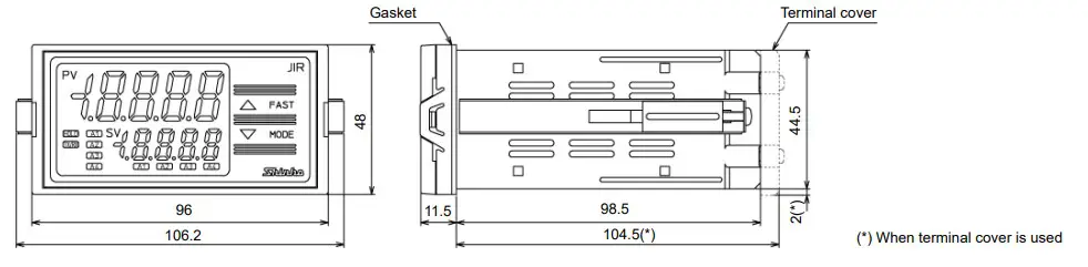
Panel Cutout (Scale: mm)

Caution
If vertical close mounting is used for the instrument, IP66 specification (Dripproof/Dust-proof) may be compromised, and all warranties will be invalidated.
Caution
As the case of the JIR-301-M is made of resin, do not use excessive force while tightening screws, or the mounting brackets or case could be damaged. 0.12 N•m of torque is recommended.
Mounting of the Unit
Mount the instrument vertically to the flat, rigid panel to ensure it adheres to the Drip-proof/Dust-proof specification (IP66).
If vertical close mounting is used for the instrument,
IP66 specification (Drip-proof/Dust-proof) may be compromised, and all warranties will be invalidated.
Mountable panel thickness: 1 to 8 mm
(1) Insert the instrument from the front side of the control panel.
(2) Attach the mounting brackets by the slots on the right and left sides of the case, and secure the instrument in place with the screws. 0.12 N•m of torque is recommended.
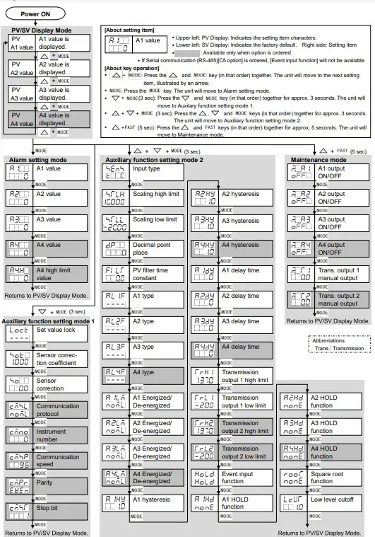
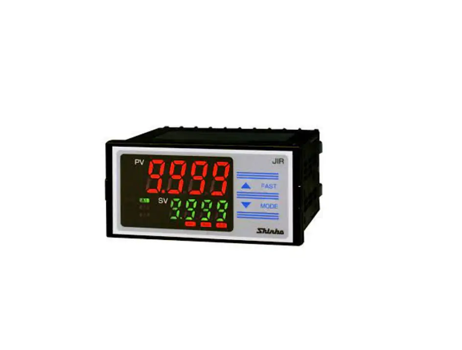
Name and Functions
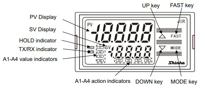
Display, Indicator
| Name | Description |
| PV Display | Indicates PV (process variable) or characters in the setting mode with the red LED. |
| SV Display | Indicates A1/A2/A3/A4 value or the set value in the setting mode with the green LED. |
| HOLD indicator | When PV is held (HOLD, Peak HOLD, Bottom HOLD), the yellow LED lights. |
| TX/RX indicator | The yellow LED lights during Serial communication (C5 option) TX (transmitting) output. |
| A1 value indicator | When A1 value is indicated on the SV Display, the green LED lights. |
| A2 value indicator | When A2 value is indicated on the SV Display, the green LED lights. |
| A3 value indicator | When A3 value is indicated on the SV Display, the green LED lights. |
| A4 value indicator | When A4 value is indicated on the SV Display, the green LED lights. (A4 option) |
| A1 action indicator | When A1 output is ON, the red LED lights. Flashes during A1 output HOLD. |
| A2 action indicator | When A2 output is ON, the red LED lights. Flashes during A2 output HOLD. |
| A3 action indicator | When A3 output is ON, the red LED lights. Flashes during A3 output HOLD. |
| A4 action indicator | When A4 output is ON, the red LED lights. Flashes during A4 output HOLD. (A4 option) |
Key
| Name | Description |
| UP key | Increases the numeric value. If High/Low limit range alarm is selected in [A4 type], and if the SV Display indicates A4 value, the SV Display indicates A4 high limit value while the UP key is pressed. |
| FAST key | Makes the set value change faster while holding down the UP/DOWN key and FAST key together. |
| DOWN key | Decreases the numeric value. |
| MODE key | Selects the setting mode, and registers the set value. |
Terminal Arrangement
Warning
- Turn the power supply to the instrument off before wiring or checking. Working on or touching the terminal with the power switched on may result in severe injury or death due to electrical shock.
- Tighten the terminal screw using the specified torque. 0.63 N•m of torque is recommended.

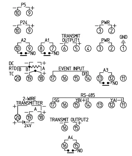
| Terminal Code | Description |
| GND | Ground |
| PWR | Power supply voltage 100 to 240 V AC or 24 V AC/DC For a 24 V AC/DC power source, ensure polarity is correct when using direct current (DC). |
| TRANSMIT OUTPUT1 | Transmission output 1 |
| A1 | A1 output |
| A2 | A2 output |
| A3 | A3 output |
| EVENT INPUT | Event input |
| TC | Thermocouple input |
| RTD | RTD input |
| DC | Direct current input, DC voltage input For direct current input (Externally mounted shunt resistor), connect a 50 shunt resistor between input terminals. |
| P24 | Insulated power output 24 V (P24 option) |
| P5 | Insulated power output 5 V (P5 option) |
| RS-485 | Serial communication (RS-485)(C5 option) |
| TRANSMIT OUTPUT2 | Transmission output 2 (T□2 option) |
| A4 | A4 output (A4 option) |
| A | Direct current input (DSB option) |
| 24V | Power for 2-wire transmitter (DSB option) |
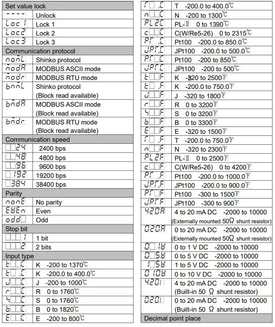
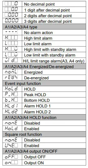
Selection Item
Key Operation Flowchart