![]()
Instruction Manual
COUNTERBALANCE
MONITOR ARM
HYDRA2A

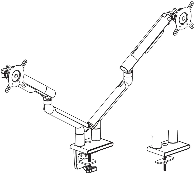
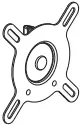
 VESA Compatible
75×75 100×100
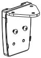
A (x2) B (x2)

![]()
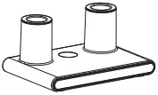
C (x2) D (x1) E (x1) F (x1) G (x1)
![]()
![]()
![]()
![]()
![]()
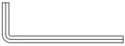
H (x1) I (x1) J (x3) M6x12 K (x1) L (x1)
![]()
![]()
![]()
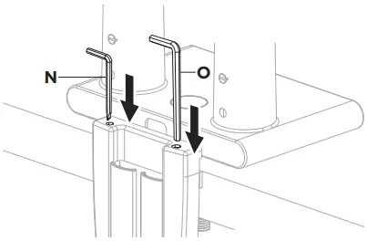
M (x1) N (x1) 4mm O (x1) 5mm P (x1) 10-13mm
![]()


{ M-A (x4) M4x12 M-B (x4) M5x12 M-C (x4) D5 } x2
1
  OR
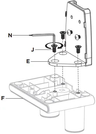
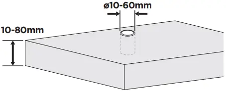
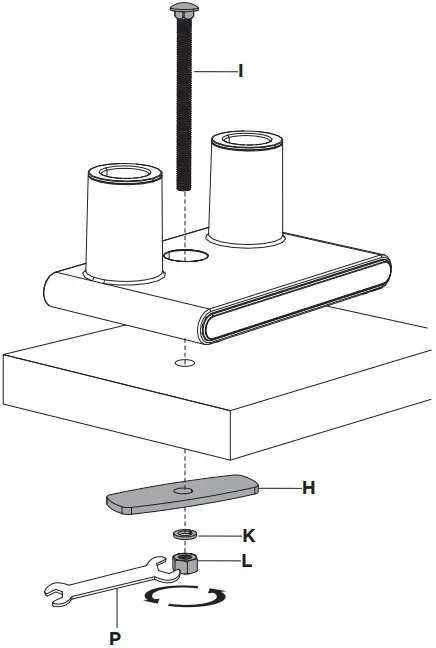
|  Desktop with Existing Through-Hole.
OR
|
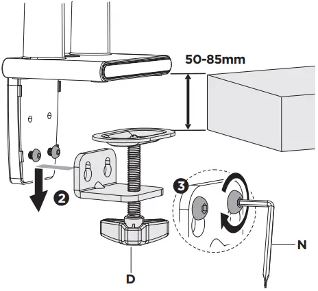
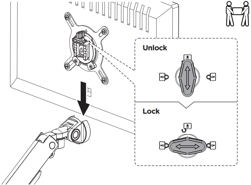
2
![]()
3
4
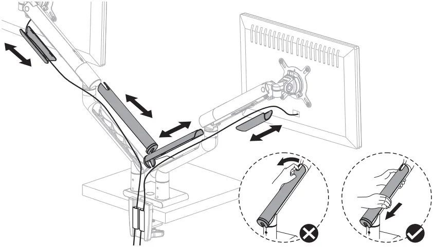
5
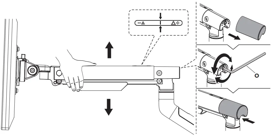
To properly balance the arm with monitors mounted, adjust the spring tension using the supplied Allen Key as follows:
First, position and firmly hold the arm horizontally as shown. Ask for assistance should you require it.
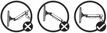
 CAUTION: To avoid damage to monitors or mount, always keep the arm in a horizontal position while making adjustments.
Again, ask for assistance if required.
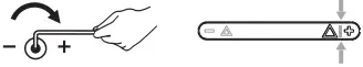
If the arm drops, turn the adjustment screw clockwise until it stays in a horizontal position.

If the arm rises, turn the adjustment screw counter-clockwise until it stays in a horizontal position.
CAUTION:
- Do not over tighten the screws.
- To prevent damage to the Tension
Indicator, never allow the Red Indicator Line move beyond the “–” and “+” found on the Left and Right Side of the tension indicator.
6
7
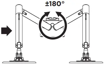
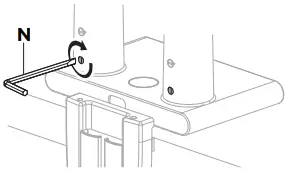 Tighten the limiting screw (do not over tighten).
Remove or loosen the limiting screw. | 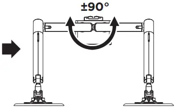 Arm can rotate 180°.
Arm can rotate without stopping. |
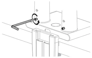
8
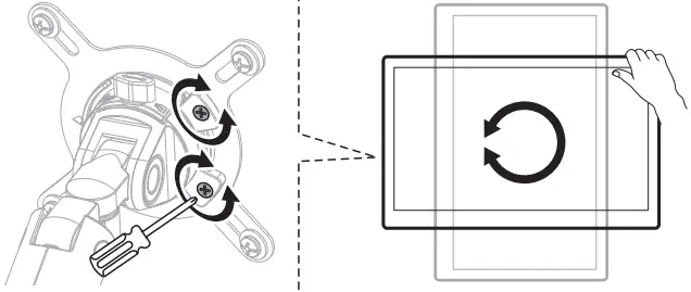
Note: If the display does not stop at your desired position,tighten the screws as shown.
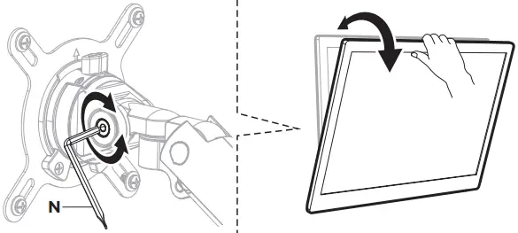
Note: If the display does not stop at your desired position, tighten the screw as shown.
 Read the entire instruction manual before you start installation and assembly. If you have any questions regarding any of the instructions or warnings, please contact your local distributor for assistance.
 CAUTION: Use with products heavier than the rated weights indicated may result in instability causing possible injury.
- Please closely follow the assembly instructions. Improper installation may result in damage or serious personal injury.
- Safety gear and proper tools must be used. This product should only be installed by professionals.
- Make sure that the supporting surface will safely support the combined weight of the equipment and all attached hardware and components.
- Use the mounting screws provided and DO NOT OVER TIGHTEN mounting screws.
- This product contains small items that could be a choking hazard if swallowed. Keep these items away from children.
- This product is intended for indoor use only. Using this product outdoors could lead to product failure and personal injury.
IMPORTANT: Ensure that you have received all parts according to the component checklist prior to installation. If any parts are missing or faulty, contact your place of purchase for a replacement.
MAINTENANCE: Check that the product is secure and safe to use at regular intervals (at least every three months).


