Christ ELECTRONIC SYSTEMS PA10006882 Touch-ItsCE OEM Glass 7 Instruction Manual
Identification
Target group
This document is not intended for end customers! Necessary safety instructions for the end customer must be passed on by the machine builder or system provider and adopted in the respective national language.
Intended use
This product has not been designed, developed and manufactured for use that creates fatal risks and hazards without exceptionally assured safety measures. These include death, injury, or serious physical harm or otherwise caused loss. These represent nuclear response monitoring, nuclear control systems, air traffic control, mass transportation control, medical life support systems, and weapons systems control.
Technical changes
Christ-Electronic Systems GmbH reserves the right to change the information, designs and technical data contained in this documentation without prior notice.
Copyright
No part of this documentation may be reproduced in any form or processed, duplicated or distributed using electronic systems without the prior written consent of Christ Electronic Systems GmbH. Even translation into another language requires written permission. This documentation is entrusted exclusively to the owner of the device or employees of Christ Electronic Systems GmbH for personal use.
Trademarks
Trademark and product names are trademarks or registered trademarks of their respective owners.
History
The following editions of the manual have already been published:
Table 1: History
Version | Comment |
10/2021 | First edition |
| 12/2021 | Adding the name plate |
Design of safety instructions
![]() DANGER
DANGER
Indicates an imminent danger
Failure to follow the instructions may result in death or serious injury
![]() WARNING
WARNING
Indicates a dangerous situation
Failure to observe this warning may result in serious injury or major damage to property
![]() CAUTION
CAUTION
Indicates a possible dangerous situation
Failure to observe the advice can result in injuries or property damage
![]() NOTICE
NOTICE
Indicates user tips and useful information
Important information to avoid malfunctions
Product description
Every industry has its own requirements for machine and system operation. To meet all of them, there are different housing variants with industry-specific features.
Above all, special areas of application or special environmental characteristics demand the greatest possible adaptability in the design of the touch panels.
In order to meet any requirements, Christ develops so-called OEM solutions. These are equipped with special customer-specific features.
The wide variety of OEM touch panels in terms of housing design, processor characteristics, interfaces, inch size and multi-touch technology enables customised implementation of customer requirements.
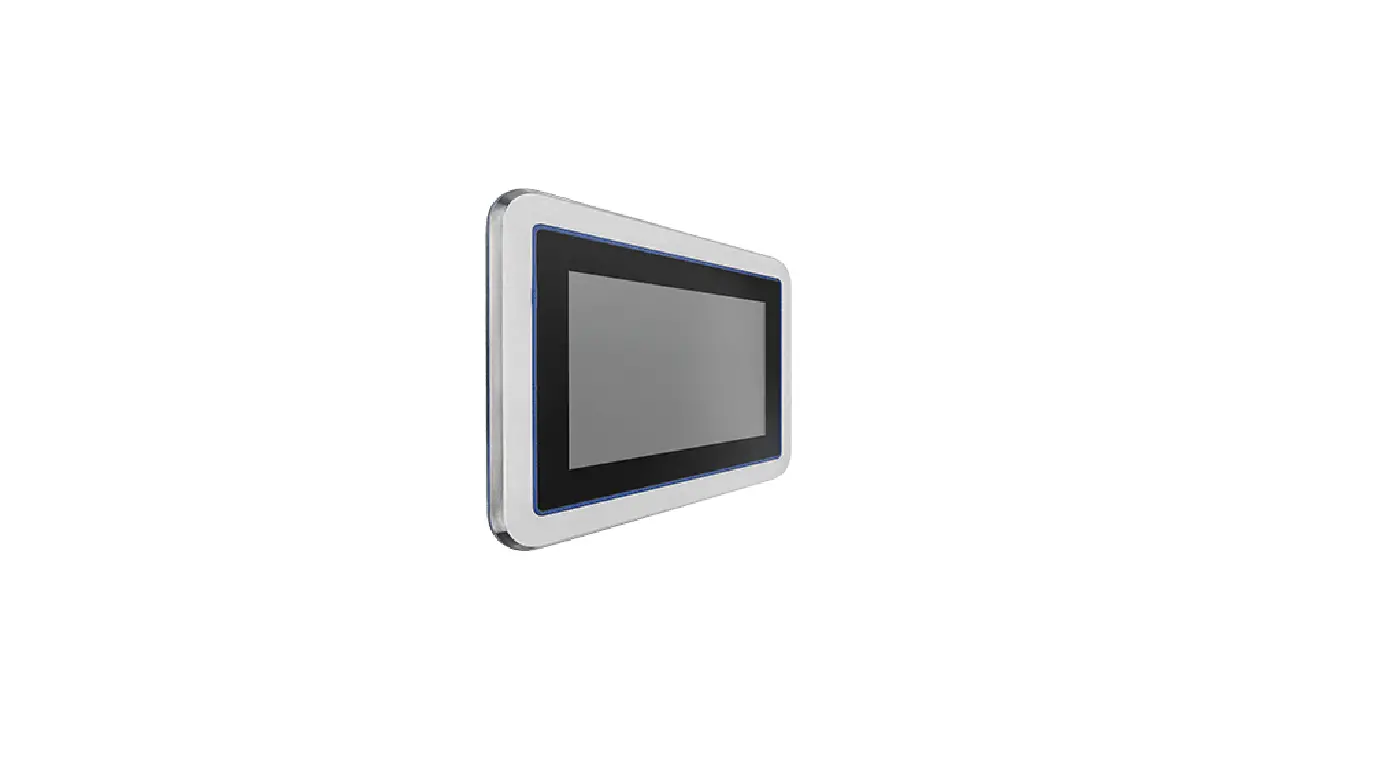
- Housing Variant CE OEM glass
Illustration 1: CE OEM glass Front
Illustration 2: CE OEM glass Reat
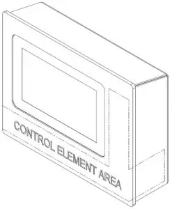

Table 2: CE OEM glass Front and CE OEM glass Rear
| 1 | Customised Mounting |
| 2 | Control Element Area |
Illustration 3: Dimensions CE OEM glass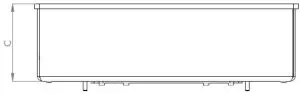
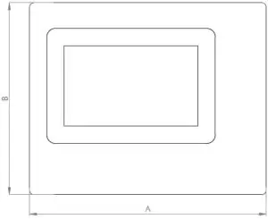
Table 3: Dimensions CE OEM glass
| Size | A | B | C |
| 7″ | 270 | 218.5 | 79* |
* With interfaces and control elements up to 145.2 mm
Table 4: Compnents of the Control Elements
| Illustration | Properties | |
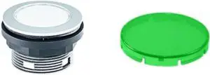
| Push button
| ||
| Series | SHORTRON® base-plate mounting | |
| Degree of protec- tion | IP65 | |
| Travel | 2.3 mm | |
| Illumination | Yes, white LED | |
| Labeling Option | Yes | |
| Front Bezel | Silver-Coloured | |
| Operating Tem- perature | -25°C … 70°C | |
| Contact Elements | max. 2 x NC / 2 x NO / 1 x NC + 1 x NO | |
| Nameplate | Blue, Yellow, Green, Transparent, White | |
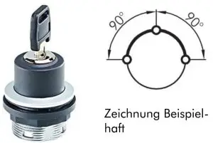
| Key Switch
Zeichnung Beispiel- haft | ||
| Series | SHORTRON® base-plate mounting | |
| Degree of protec- tion | IP65 | |
| Switching function | Maintained action | |
| Illumination | No | |
| Labeling Option | No | |
| Front Bezel | Silver-Coloured | |
| Operating Tem- perature | -25°C … 70°C | |
| Contact Elements | max. 2 x NC / 2 x NO / 1 x NC + 1 x NO | |
| Illustration | Properties | |
| Emergency Stop
| ||
| Series | QUARTEX®-R | |
| Type | QRUV | |
| Degree of protec- tion | IP65 | |
| Illumination | No | |
| Labeling Option | No | |
| Front Bezel | Yellow | |
| Operating Tem- perature | -30°C … 70°C | |
| Contact Elements | max. 5 (NC / NO) | |
| Switching Position Indicator | Yes | |
| Release | Twist right or left | |
| Anti-lock Collar | Yes | |
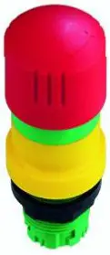
Illustration 4: Positions of the Control Elements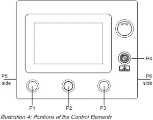
| P1 | Push Button, non latching, normally open, C1 24 VDC, transpar- ent lens, lighted, labelled |
| P2 | Dummy Plug |
| P3 | Push Button, non latching, normally open, C1 24 VDC, transpar- ent lens, lighted, labelled |
| P4 | Keylock Switch, latching, normally open, 1 x 90°, Shape V, 1 x key re-movable position (left) |
| P5 | Push Button, non latching, normally open, C13, C14 and C23, C24 floating, transparent lens, lighted |
| P6 | Dummy Plug |
| Emergency Stop | 1 x Emergency Stop |
Description Hardware
- External Interfaces
Intercontec 627 AEG A 384 MD 36 00 002K 600 Table 5: Pinout Intercontec 627 AEG A 384 MD 36 00 002K 600
PIN Function Description PIN Function Description 1 GND Ground 14 E_C3 Emergency Stop Contact 3 2 + 24 V + 24 VDC 15 E_C6 Emergency Stop Contact 6 3 Foot Switch C24 Foot Switch Contact 24 16 E_C5 Emergency Stop Contact 5 4 Digital In- put 1 Digital Input 1 17 E_C8 Emergency Stop Contact 8 5 Digital Output 1 Digital Output 1 18 E_C7 Emergency Stop Contact 7 6 Digital In- put 2 Digital Input 2 19 P5_C13 Position 5 Contact 13
7 P3_C2 Position 3 Contact 2 20 P5_C14 Position 5 Contact 14
8 P3_LED Position 3 LED 21 P5_C23 Position 5 Contact 23
9 P1_C2 Position 1 Contact 2 22 P5_C24 Position 5 Contact 24
10 P1_LED Position 1 LED 23 P4_C13 Position 4 Contact 13
11 E_C2 Emergency Stop Contact 2 24 P4_C14 Position 4 Contact 14
12 E_C1 Emergency Stop Contact 1 25 NC Not Connected 13 E_C4 Emergency Stop Contact 4 26 FE Functional Earth
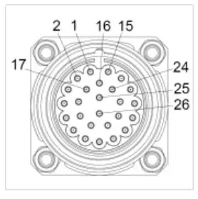 Table 5: Pinout Intercontec 627 AEG A 384 MD 36 00 002K 600
Binder 86 0632 1000 00004
Table 6: Pinout Binder 86 0632 1000 00004
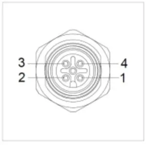
| PIN | Function | Description | |
| 1 | + 24 V | + 24 VDC | |
| 2 | + 24 V | + 24 VDC | |
| 3 | GND | Ground | |
| 4 | Foot Switch C24 | Foot Switch Contact 24 |
Binder 09 3732 90 04
Table 7: Pinout Binder 09 3732 90 04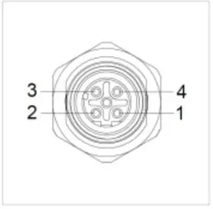
| PIN | Function | Description | |
| 1 | TX + | Transmit Data + | |
| 2 | RX + | Receive Data + | |
| 3 | TX – | Transmit Data – | |
| 4 | RX – | Receive Data – |
Environmental Conditions
![]() WARNING
WARNING
Insufficient air supply to the device Overheating
- Never cover the device completely or operate it in a small, unventilated housing
- IP Protection Class
The protection class only can be guaranteed under the following conditions:- The device is installed correctly
- All components and covers of the interfaces are assembled
- Compliance with all environmental conditions
Assembly and Commissioning
Assembly and Commissioning
This chapter describes all the steps for assembly. The following warnings are safety instructions that must be applied throughout the assembly chapter and in every other life cycle of the device.
![]() DANGER
DANGER
Danger from electric shock, explosion or electric arc
Serious injury or death
- Pull out the mains plug and do not open the covers
![]() WARNING
WARNING
Dropping a device
Injuries and bruises to the legs and / or feet
- Wear safety shoes
Note for the installation site
This device is not designed for outdoor use.
Make sure that the ambient temperature and humidity are within the ranges which are specified under
Environmental Conditions.
Do not install the device directly in the sunlight.
Make sure that the device is installed so that is accessible for the operator.
Installation instructions
Check the package contents for any visible damage and for completeness.
In case of damage, do not install the device and contact the Christ Service.
- Mounting CE OEM glass
Illustration 5: Mounting CE OEM glass
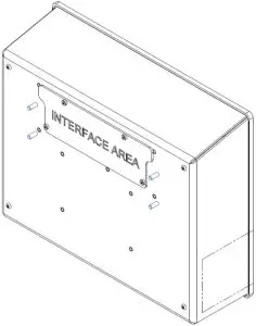
The unit is mounted on the marked threaded bolts. The customer determines the fastening utensils and the tightening torque. Christ accepts no liability for damage caused by this fastening.
Maintenance
The following chapter describes maintenance measures that can be performed by a qualified end user.
- Cleaning
 DANGER
Triggering unintended functions
Loss of control of the plant / machine / device- The unit may only be cleaned when it is switched off or unplugged.
To clean the device, use a soft cloth moistened with detergent solution or screen cleaner.
The cleaning agent must not be applied directly to the device. Under no circumstances may aggressive solvents, chemicals or scouring agents be used.
- The unit may only be cleaned when it is switched off or unplugged.
- Maintenance
It does not require any maintenance on the part of the user.
Technical Data
- Mechanical Specifications
Table 8: Mechanical SpecificationsHousing Aluminium / Silver, Black Weight max. 1.5 kg Dimensions See Table Dimensions Mounting Customised Mounting Cooling Passive - Electromagnetic Compatibility
Table 9: Electromagnetic CompatibilityEmitted Interference EN55032 Class A Immunity of supply line DC ±2 kV according to IEC 61000-4-4; EFT ± 0,5 kV according to IEC 61000-4-5; Surge asymmetrical
Immunity of signal lines ±1 kV according to IEC 61000-4-4; EFT ESD ± 4 kV Contact discharge according to EN61000-4-2 ± 8 kV Air discharge according to EN 61000-4-2
Immunity of conducted emission 3 V 150 kHz – 80 MHz, 80% AM nach IEC 61000-4-6 Immunity of high-frequency radi- ation 3 V/m 80 MHz – 1 GHz, 80% AM nach IEC 61000-4-3 3 V/m 1 GHz – 6 GHz, 80% AM nach IEC 61000-4-3
- Environmental Conditions
Table 10: Environmental ConditionsOperating Temperature 0 ~ 50 °C Storage Temperature -10 ~ 70 °C Humidity 5 ~ 80 % (non condensing) Protection Class IP65 (IP20 rear) Transportation and Storage Suitable packing increases shock resistance max. Installation Altitude 2000 m Cooling Natural Air Convection - Display Specifications
Table 11: Display SpecificationsColor Depth 8 bit Lifetime min. 50,000 h Viewing Angle (right/left/up/down) min. 85°/85°/85°/85° Backlight LED Touch Technology PCAP NOTICE
 Pixel Errors
Due to the manufacturing process, displays may contain faulty pixels (pixel er- rors), which do not constitute a claim or warranty.
The international standard ISO 9241-307:2009 defines, on an international level, the maximum possi- ble pixel errors in an LC-display. This standard discribes different error types, in consideration of differ- ent pixel error classes.
There are the following pixel error classes, each with three differnet error types.
| Maximum acceptable errors per 1 Mio. pixels according to ISO 9241-307:2009 | ||||
| error class | error type 1 pixel constantly il- luminatied | error type 2 pixel constantly dark | error type 3 subpixel con- stantly illumi- natied | error type 4 subpixel con- stantly dark |
| 0 | 0 | 0 | 0 | 0 |
| I | 1 | 1 | n = 0 to 2 2 – n | 2 x n + 1 |
| II | 2 | 2 | n = 0 to 5 5 – n | |
| 2 x n | ||||
| III | 5 | 15 | max. 50 | max. 50 |
| IV | 50 | 150 | max. 150 | max. 150 |
Why this classification of errors?
Each pixel of a display contains three subpixels which have the basic colors red, green and blue. The combination makes it possible to show a wide spectrum of colors.
Considering for example the display solution of 1280 x 800 pixels, thereof a total of 1,024000 pixels or 3,072000 subpixels are embedded in the display area. This means , the display holds 3,072000 single transistors at an area of 261.1 mm by 163.2 mm.
These figures make it clear that it is not possible to specifically produce defect-free displays even by today’s manufacturing standards.
Christ Electronic Systems GmbH therefore adapts to the corresponding requirements of most international manufacturers. The displays must always comply with error class II. If the permissible number of errors of the pixel error class II is not exceeded, there is also no complaintable “failure” of the display.
Referring to the calculation, the following errors can occur in the display:
- Max. 2 constantly illuminated and 2 constantly dark pixels
- Max. 5 constantly illuminated or 10 constantly dark subpixel
Avoid burn-in on displays
![]() NOTICE
NOTICE
Images that do not change
“Image shadows”, “ghost images” arise
- Changing displayed images, screen saver, energy-saving mode
With LC displays, so-called “ghost images” or “image shadows” can occur under certain circumstances.
These are images that remain from the previous image and are felt to be “burnt into” the display. These do not remain forever. If “image shadows” occur, the device should be switched off for a longer period of time so that the burnt-in image disappears.
To avoid “ghost images” or “image shadows”, the following behaviour is recommended:
- Do not display still images over an extended period of time
- Change standing images at short intervals
- Switch off the unit or use the energy-saving mode when you do not need it
- Use the screen saver function
Standards and Approvals
CE Marking![]() The device has been tested in accordance with the applicable EU directives and the associated harmonized standards.
The device has been tested in accordance with the applicable EU directives and the associated harmonized standards.
NOTICE![]() Decleration of Conformity
Decleration of Conformity
The declaration of Conformity can be downloaded from the Christ Electronic Systems Homepage.
![]() RoHS
RoHS
The device complies with the requirement of the EU Directive RoHS 2011/65/EU.
Electromagnetic Compatibility
The device complies with the requirements of the EU Electromagnetic Compatibility Directive 2014/30/EU with the harmonized standards listed below:
| EN 55032: 2015 Class A | Electromagnetic compatibility of multimedia equipment – Emission Requirements |
| EN 55035: 2017 | Electromagnetic compatibility of multimedia equipment – Immunity requirements |
FCC Approval
![]() The device meets the requirements of FCC for approval in the USA and Canada. This has been tested and confirmed by SGS.
The device meets the requirements of FCC for approval in the USA and Canada. This has been tested and confirmed by SGS.
FCC (Federal Communications Commission)
The device complies with Part 15 of the FCC Rules. Operation is subject to the following two conditions:
- This device may not cause any harmful
- This device must accept any interference received, including interference that may cause undesired
Changes or modifications not expressly approved by the party responsible for compliance could void the user’s authority to operate the equipment.
NOTE: This equipment has been tested and found comply with the limits of Class A digital device, pursu- ant to part 15 of the FCC Rules. These limits are designed to provide reasonable protection against harmful interference in a commercial environment. This equipment generates, uses and can radiate ra- dio frequency energy and, if not installed and used in accordance with the instructions, may cause harmful interference to radio communications. Operation of this equiment in a resident area is likely to cause harmful interference in which case the user will be required to correct the interference at his own expense.
Validity
Touch-it CE OEM glass 7, Prod. ID: PA10006882
Touch-it CE OEM glass 7, Prod. ID: PA10xxxxxx
Where “xxxxxx” in the ID Number may be any numeric characters. These models are variants of the Touch-it CE OEM glass 7 and are different regarding the interface connectors and the pushbuttons. These variants are subset of the ID: PA100006882.
Name Plate
Illustration 6: Name Plate
Alpenstra(le 34
87700 Memmingen![]() ELECTRONIC SYSTEMS
ELECTRONIC SYSTEMS
www.chnst-es.com
710331
Touch-it CE OEM glass 7
Prod. ID: PA10006882 Rev. 1
Serial no.: 0216031-000-001 (410.2021)
SW-Bundle Test123
Rev.: -1
Input: = 24V
MAC: 12:34:56:78:90:ab
12:34:56:78:90:ac
12:34:56:78:90:ad
FCC ID: 2AVB6-PA10006882
Serial No.![]()

Environmentally Appropriate Disposal
The device must not be disposed of with domestic waste.
 The appliance complies with the requirement of the EU Directive WEEE 2012/19/EU, which is symbolised by the symbol with the crossed-out dustbin.
In order to enable environmentally friendly recycling, the various materials must be separated from one another.
Disposal must be carried out in accordance with the applicable legal regulations.
| Component parts | Disposal |
| Enclosure | Metal Recycling |
| Electronic | Electronics Recycling |
| Paper / cardboard packaging | Paper / Cardboard boxes Recycling |
| Plastic packing materials | Plastics Recycling |
Technical Support
Despite the highest quality standards and detailed function tests of all our products, daily use of our devices can always lead to damage or failure of a wearing part. The failure of a machine in production costs a lot of money. That is why the Christ company processes complaints as quickly as possible.
You can send the device to us without prior notice. All you need to do is fill out the cover letter for the repair and enclose it with the touch panel or IPC so that the service department can start the repair quickly. When the device arrives, it goes through a defined process that clearly documents all processes and makes the respective status traceable. As soon as your panel or IPC is registered in our system, you will receive a confirmation of receipt so that you can also get a precise overview.
Technical Support can be contacted as follows:
Service, Repair and Technical Support
Phone: +49 8331 8371-500
Fax: +49 8331 8371-497
E-Mail: [email protected]
Or directly via the Homepage.
Christ Service
Device Seal
A device seal is affixed to every Christ device in order to prove whether the device has been opened by a third party. In case of a defect, please do not open the device, but contact our service department.
They will discuss the further procedure with you.

![]()
![]()


