
DELTA DVP04PT06PT-S Temperature Measurement
Thank you for choosing Delta DVP series PLC. DVP04/06PT-S is able to receive 4/6 points of RTDs and convert them into 16-bit digital signals. Through FROM/TO instructions in DVP Slim series MPU program, the data can be read and written. There are many 16-bit control registers (CR) in modules. The power unit is separate from it and is small in size and easy to install.
DVP04/06PT-S is an OPEN-TYPE device. It should be installed in a control cabinet free of airborne dust, humidity, electric shock and vibration. To prevent non-maintenance staff from operating DVP04/06PT-S, or to prevent an accident from damaging DVP04/06PT-S, the control cabinet in which DVP04/06PT-S is installed should be equipped with a safeguard. For example, the control cabinet in which DVP04/06PT-S is installed can be unlocked with a special tool or key.
- DO NOT connect AC power to any of I/O terminals, otherwise serious damage may occur. Please check all wiring again before DVP04/06PT-S is powered up. After
- DVP04/06PT-S is disconnected, Do NOT touch any terminals in a minute. Make sure that the ground terminal
 on
on - DVP04/06PT-S is correctly grounded in order to prevent electromagnetic interference.
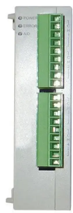
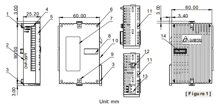
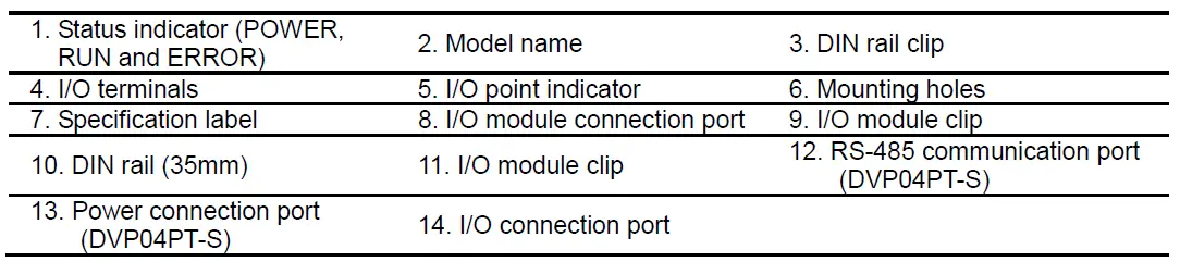
Product Profile & Dimension

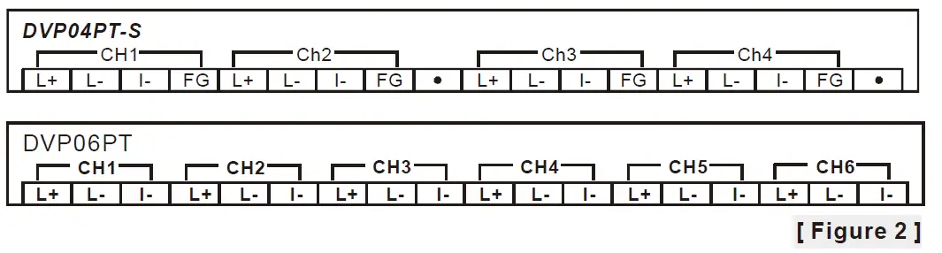
- I/O Terminal Layout

External Wiring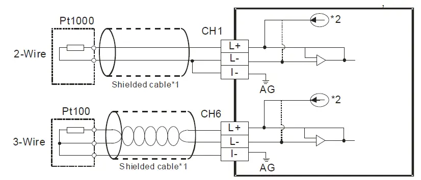
- Note1: Use only the wires that are packed with the temperature sensor for analog input and separate them from other power line or any wire that may cause noise.
Note 2: 3-wire RTD sensor provides a compensation loop that can be used to subtract the wire resistance while 2-wire RTD sensor has no mechanism to compensate. Use cables (3-wired) with the same length (less than 200 m) and wire resistance of less than 20 ohm. - Note3: If there is noise, please connect the shielded cables to the system earth point, and then ground the
system earth points or connect it to the distribution box.
Note 4: Please keep wires as short as possible when connecting the module to a device whose temperature is going to be measured, and keep the power cable used as far away from the cable connected to a load as possible to prevent noise interference. - Note 5: Please connect a power supply module and on the temperature module to a system
ground, and then ground the system ground or connect the system ground to a distribution box.
Electrical Specifications
| Max. rated power consumption | 2W |
| Operation/storage | Operation: 0°C~55°C (temp.), 5~95% (humidity), pollution degree 2 Storage: -25°C~70°C (temp.), 5~95% (humidity) |
| Vibration/shock resistance | International standards: IEC61131-2, IEC 68-2-6 (TEST Fc)/ IEC61131-2 & IEC 68-2-27 (TEST Ea) |
| Series connection to DVP-PLC MPU | The modules are numbered from 0 to 7 automatically by their distance from MPU. No.0 is the closest to MPU and No.7 is the furthest. Maximum 8 modules are allowed to connect to MPU and will not occupy any digital I/O points. |
Functional Specifications
| DVP04/06PT-S | Celsius (°C) | Fahrenheit (°F) |
| Analog input channel | 4/6 channels per module | |
| Sensors type | 2-wire/3-wire Pt100 / Pt1000 3850 PPM/°C (DIN 43760 JIS C1604-1989) / Ni100 / Ni1000 / LG-Ni1000 / Cu100 / Cu50/ 0~300Ω/ 0~3000Ω | |
| Current excitation | 1.53mA / 204.8uA | |
| Temperature input range | Please refer to the temperature/digital value characteristic curve. | |
| Digital conversion range | Please refer to the temperature/digital value characteristic curve. | |
| Resolution | 0.1°C | 0.18°F |
| Overall accuracy | ±0.6% of full scale during 0 ~ 55°C (32 ~ 131°F) | |
| Response time | DVP04PT-S: 200ms/channel; DVP06PT-S: 160/ms/channel | |
| Isolation method (between digital and analog circuitry) | There is no isolation between channels. 500VDC between digital/analog circuits and Ground 500VDC between analog circuits and digital circuits 500VDC between 24VDC and Ground | |
| Digital data format | 2’s complement of 16-bit | |
| Average function | Yes (DVP04PT-S: CR#2 ~ CR#5 / DVP06PT-S: CR#2) | |
| Self diagnostic function | Every channel has the upper/lower limit detection function. | |
| RS-485 Communication Mode | Supported, including ASCII/RTU mode. Default communication format: 9600, 7, E, 1, ASCII; refer to CR#32 for details on the communication format. Note1: RS-485 cannot be used when connected to CPU series PLCs. Note2: Refer to Slim Type Special Module Communications in the appendix E of the DVP programming manual for more details on RS-485 communication setups. |
The unit of temperature would be displayed as 0.1°C/0.1°F. If the temperature unit is set to be Fahrenheit, the second decimal place would not be shown.
Control Register
| CR# | Address | Latched | Attribute | Register content | Description | |||
| #0 | H’4064 | O | R | Model name (Set up by the system) | DVP04PT-S model code= H’8A DVP06PT-S model code = H’CA | |||
|
#1 |
H’4065 |
X |
R/W |
CH1~CH4 Mode setting | b15~12 | b11~8 | b7~4 | b3~0 |
| CH4 | CH3 | CH2 | CH1 | |||||
| Take CH1 mode (b3,b2,b1,b0) for example. 1. (0,0,0,0): Pt100 (default) 2. (0,0,0,1): Ni100 3. (0,0,1,0): Pt1000 4. (0,0,1,1): Ni1000 5. (0,1,0,0): LG-Ni1000 6. (0,1,0,1): Cu100 7. (0,1,1,0): Cu50 8. (0,1,1,1): 0~300 Ω 9. (1,0,0,0): 0~3000 Ω 10. (1,1,1,1)The channel is disabled. Mode 8 and 9 are only available for DVP04PT-S V4.16 or later and DVP06PT-S V4.12 or later. | ||||||||
|
#2 |
H’4066 |
O |
R/W | DVP04PT-S: CH1 average number | Number piece of readings used for the calculation of “average” temperature on CH1. Setting range: K1~K20. Default setting is K10. | |||
|
— | DVP06PT-S: CH1~CH6 average number | Number piece of readings used for the calculation of “average” temperature on CH1 ~ 6. Setting range: K1~K20. Default setting is K10. | ||||||
|
#3 |
H’4067 |
O |
H’4067 | DVP04PT-S: CH2 average number | Number piece of readings used for the calculation of “average” temperature on CH2. Setting range: K1~K20. Default setting is K10. | |||
|
#4 |
H’4068 |
O |
H’4068 | DVP04PT-S: CH3 average number | Number piece of readings used for the calculation of “average” temperature on CH3. Setting range: K1~K20. Default setting is K10. | |||
|
#5 |
H’4069 |
O |
H’4069 | DVP04PT-S: CH4 average number | Number piece of readings used for the calculation of “average” temperature on CH4. Setting range: K1~K20. Default setting is K10. | |||
| #6 | H’406A | X | R | CH1 average degrees | DVP04PT-S: Average degrees for CH1 ~ 4 DVP06PT-S: Average degrees for CH1 ~ 6 Unit: 0.1°C, 0.01 Ω (0~300 Ω), 0.1 Ω (0~3000 Ω) | |||
| #7 | H’406B | X | R | CH2 average degrees | ||||
| #8 | H’406C | X | R | CH3 average degrees | ||||
| #9 | H’406D | X | R | CH4 average degrees | ||||
| #10 | — | X | R | CH5 average degrees | ||||
| #11 | — | X | R | CH6 average degrees | ||||
| #12 | H’4070 | X | R | CH1 average degrees | DVP04PT-S: Average degrees for CH1 ~ 4 DVP06PT-S: Average degrees for CH1 ~ 6 Unit: 0.1°C, 0.01 Ω (0~300 Ω), 0.1 Ω (0~3000 Ω) | |||
| #13 | H’4071 | X | R | CH2 average degrees | ||||
| #14 | H’4072 | X | R | CH3 average degrees | ||||
| #15 | H’4073 | X | R | CH4 average degrees | ||||
| #16 | — | X | R | CH5 average degrees | ||||
| #17 | — | X | R | CH6 average degrees | ||||
| #18 | H’4076 | X | R | Present temp. of CH1 | DVP04PT-S: Present temperature of CH 1~4 | |||
| #19 | H’4077 | X | R | Present temp. of CH2 | ||||
| CR# | Address | Latched | Attribute | Register content | Description | |||||
| #20 | H’4078 | X | R | Present temp. of CH3 | DVP06PT-S: Present temperature of CH1~6 Unit: 0.1°C, 0.01 Ω (0~300 Ω), 0.1 Ω (0~3000 Ω) | |||||
| #21 | H’4079 | X | R | Present temp. of CH4 | ||||||
| #22 | — | X | R | Present temp. of CH5 | ||||||
| #23 | — | X | R | Present temp. of CH6 | ||||||
| #24 | H’407C | X | R | Present temp. of CH1 | DVP04PT-S: Present temperature of CH 1~4 DVP06PT-S: Present temperature of CH 1~6 Unit: 0.1°C, 0.01 Ω (0~300 Ω), 0.1 Ω (0~3000 Ω) | |||||
| #25 | H’407D | X | R | Present temp. of CH2 | ||||||
| #26 | H’407E | X | R | Present temp. of CH3 | ||||||
| #27 | H’407F | X | R | Present temp. of CH4 | ||||||
| #28 | — | X | R | Present temp. of CH5 | ||||||
| #29 | — | X | R | Present temp. of CH6 | ||||||
| #29 | H’4081 | X | R/W | DVP04PT-S: PID mode setup | Set H’5678 as PID mode and other values as normal mode Default value is H’0000. | |||||
| #30 | H’4082 | X | R | Error status | Data register stores the error status. Refer to the error code chart for details. | |||||
|
#31 | H’4083 | O | R/W | DVP04PT-S: Communication address setup | Set up the RS-485 communication address; setting range: 01~254. Default: K1 | |||||
| — | X | R/W | DVP06PT-S: CH5~CH6 Mode setting | CH5 mode: b0 ~ b3 CH6 mode: b4 ~ b7 See CR#1 for reference | ||||||
|
32 |
H’4084 |
O |
R/W |
DVP04PT-S: Communication format setting | For baud rate, the settings are 4,800/9,600/19,200/38,400/57,600/ 115,200 bps. Communication format: ASCII: 7,E,1 / 7,O,1 / 8,E,1 / 8,O,1 / 8,N,1 RTU: 8,E,1 / 8,O,1 / 8,N,1 Factory default : ASCII,9600,7,E,1 (CR#32=H’0002) Refer to ※CR#32 communication format settings at the end of this table for more information. | |||||
|
— |
X |
R/W |
DVP06PT-S: CH5~CH6 Error LED indicator setting | b15~12 | b11~9 | b8~6 | b5~3 | b2~0 | ||
| ERR LED | reserved | CH6 | CH5 | |||||||
| b12~13 correspond to CH5~6, when bit is ON, the scale exceeds the range, and the Error LED indicator flashes. | ||||||||||
|
#33 |
H’4085 |
O |
R/W | DVP04PT-S: CH1~CH4 Reset to default setting And Error LED indicator setting | b15~12 | b11~9 | b8~6 | b5~3 | b2~0 | |
| ERR LED | CH4 | CH3 | CH2 | CH1 | ||||||
| If b2~b0 are set to 100, all the setting values of CH1 will be reset to the defaults. To reset all channels to defaults, set b11~0 to H’924 (DVP04PT-S supports single and all channels reset; DVP06PT-S supports all channels reset only). b12~15 correspond to CH1~4, when bit is ON, the scale exceeds the range, and the Error LED indicator flashes. | ||||||||||
|
— |
X |
R/W |
DVP06PT-S: CH1~CH4 Reset to default setting And CH1~CH4 Error LED indicator setting | |||||||
| #34 | H’4086 | O | R | Firmware version | Display version in hexadecimal. ex: H’010A = version 1.0A | |||||
| #35 ~ #48 For system use | ||||||||||
| Symbols: O means latched. (Supported with RS485, but does not support when connecting to MPUs.) X means not latched. R means can read data by using FROM instruction or RS-485. W means can write data by using TO instruction or RS-485. | ||||||||||
- Added the RESET function is only for 04PT-S modules with firmware V4.16 or later and not available for 06PT-S. Connect the module power input to 24 VDC and write H’4352 into CR#0 and then turn the power off and on again; all parameters in modules, including communication parameters are restored to factory defaults.
- If you want to use Modbus address in decimal format, you can transfer a hexadecimal register to decimal format and then add one to have it become a decimal Modbus register address. For example transferring the address “H’4064” of CR#0 in hexadecimal format to decimal format, to have the result 16484 and then adding one to it, you have 16485, the Modbus address in decimal format.
- CR#32 communication format settings: for DVP04PT-S modules with firmware V4.14 or previous versions, b11~b8 data format selection is not available. For ASCII mode, the format is fixed to 7, E, 1 (H’00XX) and for RTU mode, the format is fixed to 8, E, 1 (H’C0xx/H’80xx). For modules with firmware V4.15 or later, refer to the following table for setups. Note that the original code H’C0XX/H’80XX will be seen as RTU, 8, E, 1 for modules with firmware V4.15 or later.
| b15 ~ b12 | b11 ~ b8 | b7 ~ b0 | |||
| ASCII/RTU, exchange low and high byte of CRC check code | Data format | Baud rate | |||
| Description | |||||
| H’0 | ASCII | H’0 | 7,E,1*1 | H’01 | 4800 bps |
| H’8 | RTU, do not exchange low and high byte of CRC check code | H’1 | 8,E,1 | H’02 | 9600 bps |
| H’2 | reserved | H’04 | 19200 bps | ||
| H’C | RTU, exchange low and high byte of CRC check code | H’3 | 8,N,1 | H’08 | 38400 bps |
| H’4 | 7,O,1*1 | H’10 | 57600 bps | ||
| H’5 | 8.O,1 | H’20 | 115200 bps | ||
- Note *1: This is only available for ASCII format.
- Ex: Write H’C310 into CR#32 for a result of RTU, exchange low and high byte of CRC check code, 8,N,1 and baud rate at 57600 bps.
- RS-485 function codes: 03’H is for reading data from registers. 06’H is for writing a data word to registers. 10’H is for writing multiple data words to registers.
- CR#30 is the error code register.
Note: Each error code will have a corresponding bit and should be converted to 16-bit binary numbers (Bit0~15). Two or more errors may happen at the same time. Refer to the chart below:
| Bit number | 0 | 1 | 2 | 3 |
| Description | Power source abnormal | The contact is not connected to anything. | Reserved | Reserved |
| Bit number | 4 | 5 | 6 | 7 |
| Description | Reserved | Reserved | average number error | Instruction error |
| Bit number | 8 | 9 | 10 | 11 |
| Description | CH1 Abnormal conversion | CH2 Abnormal conversion | CH3 Abnormal conversion | CH4 Abnormal conversion |
| Bit number | 12 | 13 | 14 | 15 |
| Description | CH5 Abnormal conversion | CH6 Abnormal conversion | Reserved | Reserved |
- Temperature/Digital Value Characteristic Curve
The mode of measuring Celsius (Fahrenheit) temperature: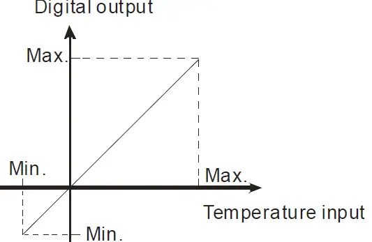
| Sensor | Temperature range | Digital value conversion range | ||
| °C (Min./Max.) | °F (Min./Max.) | °C (Min./Max.) | °F (Min./Max.) | |
| Pt100 | -180 ~ 800°C | -292 ~ 1,472°F | K-1,800 ~ K8,000 | K-2,920 ~ K14,720 |
| Ni100 | -80 ~ 170°C | -112 ~ 338°F | K-800 ~ K1,700 | K-1,120 ~ K3,380 |
| Pt1000 | -180 ~ 800°C | -292 ~ 1,472°F | K-1,800 ~ K8,000 | K-2,920 ~ K14,720 |
| Ni1000 | -80 ~ 170°C | -112 ~ 338°F | K-800 ~ K1,700 | K-1,120 ~ K3,380 |
| LG-Ni1000 | -60 ~ 200°C | -76 ~ 392°F | K-600 ~ K2,000 | K-760 ~ K3,920 |
| Cu100 | -50 ~ 150°C | -58 ~ 302°F | K-500 ~ K1,500 | K-580 ~ K3,020 |
| Cu50 | -50 ~ 150°C | -58 ~ 302°F | K-500 ~ K1,500 | K-580 ~ K3,020 |
| Sensor | Input resistor range | Digital value conversion range | ||
| 0~300Ω | 0Ω ~ 320Ω | K0 ~ 32000 | 0~300Ω | 0Ω ~ 320Ω |
| 0~3000Ω | 0Ω ~ 3200Ω | K0 ~ 32000 | 0~3000Ω | 0Ω ~ 3200Ω |
- When CR#29 is set to H’5678, CR#0 ~ CR#34 can be used for PID settings with DVP04PT-S version V3.08 and above.
| PID Mode description | |||||||
| CR# | Keep | R/W | CR# | Keep | R/W | ||
| #0 | O | R | Model name | #24 | O | R/W | CH1 KD | |
| #1 | X | R/W | CH1~CH4 Mode setting | #25 | O | R/W | CH2 KD | |
| #2 | X | R | PID Output % at CH1 | #26 | O | R/W | CH3 KD | |
| #3 | X | R | PID Output % at CH2 | #27 | O | R/W | CH4 KD | |
| #4 | X | R | PID Output % at CH3 | Run/Stop & Auto tuning
Bit0:CH1 PID Run/Stop Bit1:CH2 PID Run/Stop Bit2:CH3 PID Run/Stop Bit3:CH4 PID Run/Stop 0=PID Stop,1=PID Run
Bit4:CH1 Auto tuning Bit5:CH2 Auto tuning Bit6:CH3 Auto tuning Bit7:CH4 Auto tuning 1: The auto tuning function is enabled. After the auto tuning is complete, the value becomes 0. | ||||
| #5 | X | R | PID Output % at CH4 | |||||
| CR#2~CR#5: 0~1000; Unit: 0.1% | ||||||||
| #6 | X | R | Average temperature (0C) at CH1 | |||||
| #7 | X | R | Average temperature (0C) at CH2 | |||||
| #8 | X | R | Average temperature (0C) at CH3 | |||||
| #9 | X | R | Average temperature (0C) at CH4 | #28 | X | R/W | ||
| CR#6~CR#9:Unit: 0.1% | ||||||||
| #10 | O | R/W | Set temperature at CH1 | |||||
| #11 | O | R/W | Set temperature at CH2 | |||||
| #12 | O | R/W | Set temperature at CH3 | |||||
| #13 | O | R/W | Set temperature at CH4 | |||||
| CR#10~CR#13: Set the PID target value (SV) | ||||||||
| #14 | O | R/W | CH1 KP | #29 | X | R/W | Enter PID mode(H’5678) K0: Exit the PID mode | |
| #15 | O | R/W | CH2 KP | |||||
| #16 | O | R/W | CH3 KP | #30 | X | R | Error code | |
| #17 | O | R/W | CH4 KP | #31 | O | R/W | CH1 Sampling time | |
| #19 | O | R/W | CH1 KI | #32 | O | R/W | CH2 Sampling time | |
| #20 | O | R/W | CH2 KI | #33 | O | R/W | CH3 Sampling time | |
| #21 | O | R/W | CH3 KI | #34 | O | R/W | CH4 Sampling time | |
| #22 | O | R/W | CH4 KI | CR#31~CR#34: 1~30; Unit: 1s | ||||
| Note: CR#29 must be set to H’5678 so as to enter the PID mode before configuring settings on other control registers. | ||||||||


