![]() AZBW10120 Motion Detector PIR MW
AZBW10120 Motion Detector PIR MW
User Guide
Disassembling the Detector
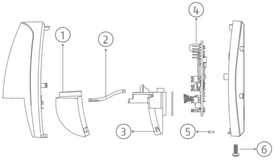
| 1 | Lens |
| 2 | LED Light Pipe |
| 3 | Lens holder |
| 4 | PCB |
| 5 | Nut |
| 6 | Casing Screw |
Printed Circuit Board (PCB)
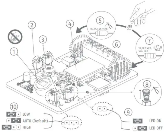
| 1 | PIR Sensor |
| 2 | AND/OR Mode OR is non EN compliant |
| 3 | 50Hz as default 60Hz remove header |
| 4 | Microwave Module |
| 5 | Tamper Resistor Headers |
| 6 | Terminals |
| 7 | Alarm Resistor Headers |
| 8 | Tamper Spring |
| 9 | LED ON/OFF |
| 10 | Sensitivity Settings |
Installation
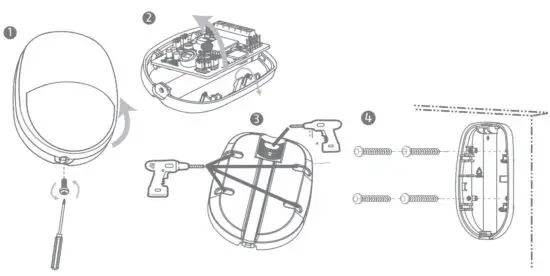
Detector Backplane Installation
Screw Model: PA_3.5 ×25
Number: 4
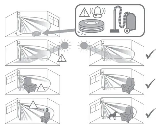
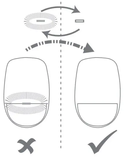
Installation Hints
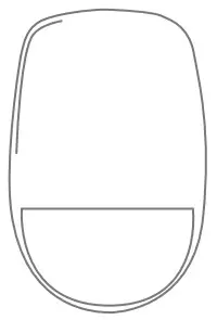
The Lens
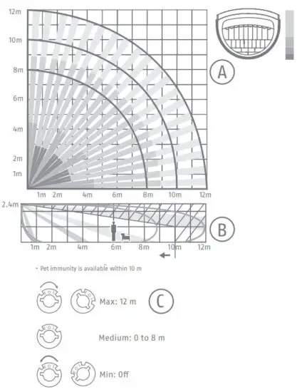
| A | Detection Range 85.9° 52 zones 4 planes | ||||||||
| B | Mounting height range from 1.8 m to 2.4 m. The recommended mounting height is 2.2 m. Note: PET immunity is available up to 10 m and at a height that is below the top plane of view | ||||||||
| C | Microwave Range Control Max: 12 m Medium: 0 to 8 m Min: Off | ||||||||
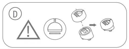
| D | To use the pet immunity function, please install a pet mask. Pet Table
|
Resistor Wiring
The detector has two methods for resistor wiring:
- Use headers to select the End of Line resistance (Control panel dependent) on the ALARM/TAMPER header pins.
- Select a resistance (Control panel dependent), and add the resistor to the ALARM/TAMPER wiring ports of the detector.
Note: If EOL (End of Line) wiring is not used, leave the headers OFF. If the headers and the header pins do not match, do not force the header, please select method 2 to wire the resistor. Method 1 and method 2 should not be used on the ALARM/TAMPER at the same time.
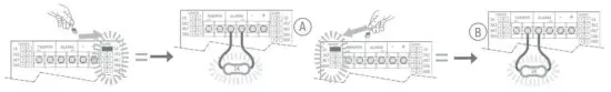
Choose the Connection Type
- Normally Closed

A Alarm Control Panel B Detector - Single End of Line Wiring
The connection shows the example:
1. Normal: 1K
2. Alarm: Infinite
3. Tamper: 0 K
A Alarm Control Panel B Detector - Double End of Line Wiring
The connection shows the example:
1. Normal: 1K
2. Alarm: 2K
3. Tamper: 0 K or infinite
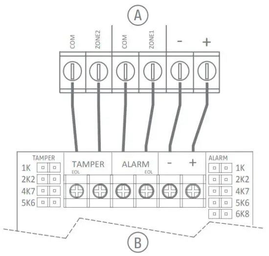
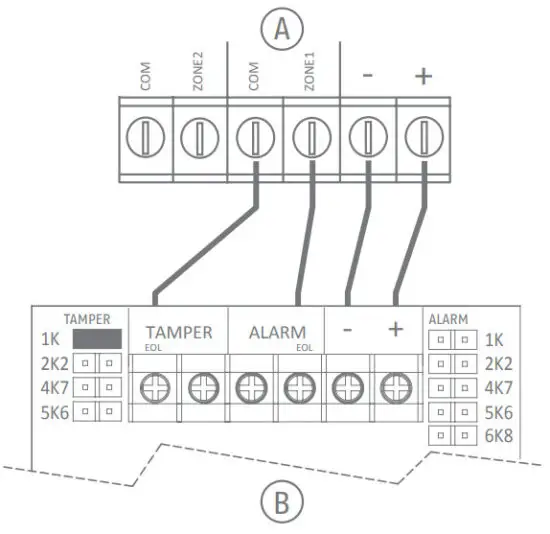
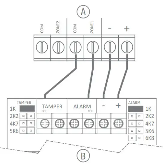
| A | Alarm Control Panel |
| B | Detector |
Powering up
Powering up:
Aft er powering on, the indicator flashes rapidly. Once the detector self-test is completed, the LED indicator will go out until the detector detects movement
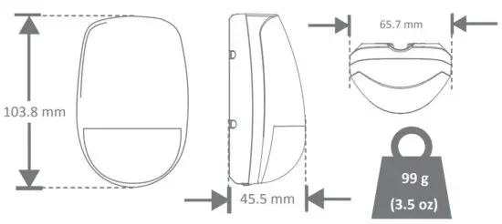
Dimension and Weight
Technical Specification
| Detection range | 12m, 85.9° |
| Detection speed | 0.3 ~ 2 m/s |
| Sensitivity | High, Auto, Low* |
| Auto sensitivity | Yes |
| Onboard EOL | Yes |
| Digital temperature compensation | Yes |
| Technology | Digital microprocessor-based |
| Sealed optics | Yes |
| Creep zone protection | Yes |
| Tamper protection | Front |
| LED indicators | Green(PIR), Orange(microwave), Blue(alarm) |
| Microwave frequency | 24Ghz (24.15Ghz to 24.25Ghz) |
| Microwave range | Potentiometer adjustment |
| Microwave transmission power | max. 18.6 mW |
| AND/OR mode | AND = PIR + MW OR = PIR / MW (shouldn’t be used with pets) |
| Pet immunity | 10Kg (With optional pet mask) |
| Power supply | 9 to 16 VDC (standard: 12 VDC) |
| Current consumption | 17mA quiescent and maximum at12V DC |
| Operating temperature | -10 °C to 40 °C (14 °F to 104 °F) |
| Storage temperature | -20 °C to 60 °C (-4 °F to 140 °F) |
| Operating humidity | 10% to 90% |
| Mounting height | 1.8 – 2.4m |
| Dimensions (HxWxD) | 103.8 mm × 65.7 mm × 45.5 mm |
| Weight | 99 g |
* Low is non-EN and non INSERT compliant.
DECLARATION OF CONFORMITY
ABUS Security-Center hereby declares that the enclosed product(s) comply with the requirements of the following directives: EMC Directive (2014/30/EU) and RoHS Directive (2011/65/EU). The full EU Declaration of Conformity text can be found at: www.abus.com/product/AZBW10120 It can also be obtained at the following address:
ABUS Security Center
GmbH & Co. KG, Linker Kreuthweg 5,
86444 Affi ng, GERMANY
Subject to technical modifications and color changes. No liability is assumed for mistakes or printing errors.
EN 50131-1:2006+A1:
2009+A2:2017
EN 50131-2-4:2008
Security Grade (SG) 2
Environmental Class (EC) II
ABUS Security-Center GmbH & Co. KG
Linker Kreuthweg 5 86444 Affing
Germany
abus.com
 User Guide")


