![]()
AEM30940 RF 2.45 GHz
Quick Start Guide EVK
FEATURES
Connectors
- 1 SMA connector for input power below -10dBm [LOW]
- 1 SMA connector for input power above -10dBm [HIGH]
- 1 screw connector + 1 JST connector for the Storage Element
- 1 screw connector for Primary Battery
- 1 screw connector for HVOUT LDO output (80mA @ 1.8 – 4.2 V)
- 1 screw connector for LVOU LDO output (20mA @ 1.2 or 1.8 V)
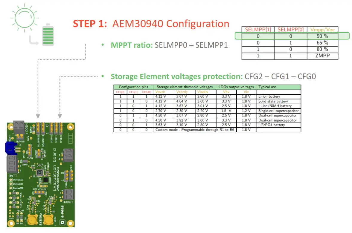
Configuration
- 2 jumpers SELMMP[x] to define the MPPT ratio linked to the harvester technology
- 3 Jumpers CFG[x] to define the storage element protection levels
- 6 resistors footprint related to the custom mode (CFG[2:0]=000)
- 2 jumpers to enable/disable the internal LDOs
- 2 jumpers to define the primary battery minimum level
- 1 jumper to set the dual cell supercapacitor BAL feature
- 1 resistors footprint to use the ZMPP feature (constant impedance)
Size
- 79mm x 49mm
- 4 x M2.5 Mounting holes
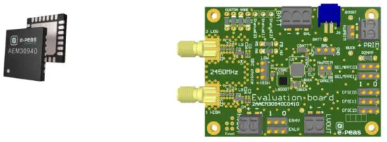
SUPPORT PCB
BOM around the AEM30940
| Designator | Description | Quantity | Manufacturer | Part Number |
| CBOOST | Ceramic Cap 22 /11, 10 V, 20 ?o, X5R 0603 | 1 | Murata | GRM188R61A226ME15D |
| CBUCK | Ceramic Cap 10 1/F, 10 V, 20 %, X5R | 1 | TDK | C1608X5R1A106M080AC |
| CHV | Ceramic Cap 10 pF, 10 V, 20 %, X5R | 1 | TDK | C1608X5R1A106M080AC |
| CLV | Ceramic Cap 10 //F, 10 V. 20 X5R | 1 | TDK | C1608X5R1A106M080AC |
| CSRC | Ceramic Cap 10 //F, 10 V. 20 %, X5R | 1 | TDK | C1608X5R1A106M080AC |
| LBOOST | Power Inductor 10 pH – 0.54 A – LPD5030V | 1 | Coilcraft | LPD5030V-103MR |
| Power Inductor 10 /EH – 0,55 A – LPS4012 | 1 | Wiirth | 744 040 321 00 | |
| LBUCK | Power Inductor 10 /tH – 0,25 A | 1 | TDK | ML21608M100WT |
| Ul | AEM30940 – Symbol QFN28 1 | 1 | order at [email protected] or Where to buy |
Matching network and RF rectifier schematic under NDA signature
Footprint & Symbol: Available on the web product page https://e-peas.com/products/energy-harvesting/rf/aem30940-3/#documentation

https://e-peas.com/products/energy-harvesting/vibration/aem30940/#documentation
- BAL option: Select “ToCn” for dual-cells supercapacitor and “GND” for any other storage
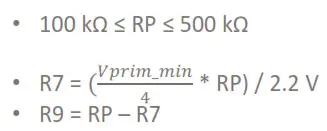
- PRIM option: Connect both jumpers “NoPRIM” or remove them if a primary battery is connected. Define the lower limit voltage on the primary battery using R7 and R8 (2.2V by default with the jumper and 0R R7 mounted)
 ZMPP resistor footprint
- LDOs Outputs Voltages: ENHV (HVOUT) – ENLV (LVOUT)
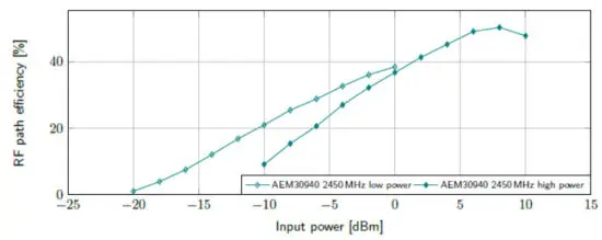
- MATCHING NETWORK + RF RECTIFIER: one matching for LOW input power (< -10 dBm) and another matching for HIGH input power (< +20 dBm)
 ZMPP resistor footprint
parciesho | palciesm | 0 | 0 |
| paneui | paigesm | T | 0 |
| paiciesm | pameu3 | 0 | T |
| paneu] | paneu] | 1 | T |
| lnchno AR | vichno Al | I AHN3 | Al N3 |
STEP 2: Connect the Storage Element (and the Primary Battery)
STEP 3: Connect the Load(s) to HVOUT / LVOUT
STEP 4: Connect the antenna to the SMA connector
• Overall efficiency from the antenna to the storage element:
STEP 5: Check the Status
| Status pins | ||
| STATUS[2] | 19 | Logic output. Asserted when the AEM performs an MPP evaluation. |
| STATUS[1] | 20 | Logic output. Asserted if the battery voltage falls below if the AEM is taking energy from the primary battery. |
| STATUS[1] | 21 | Logic output. Asserted when the LDOs can be enabled. |
© 2020 e-peas S.A.
www.e-peas.com


