![]()
AEM10300
Quick Start Guide EVK
AEM10300 Solar Battery Charger
FEATURES
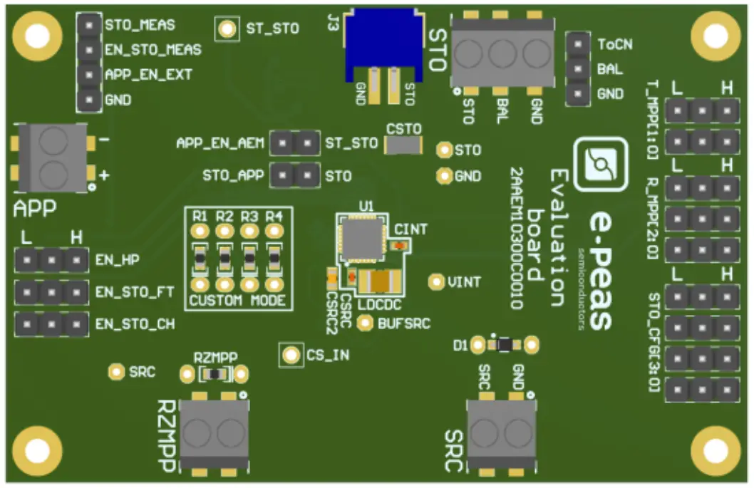
Connectors
- 1 screw connector for the source
- 1 screw connector + 1 JST connector for the Storage Element
- 1 screw connector for the application supply
- 1 screw connector for RZMPP
Configuration
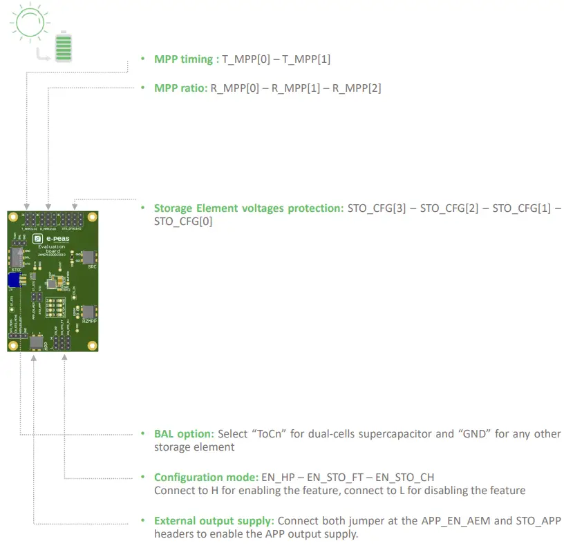
- 3 jumpers R_MPP[x] to define the MPP ratio linked to the harvester technology
- 2 jumpers T_MPP[x] to define the MPP timing
- 4 jumpers STO_CFG[x] to define the storage element protection levels
- 4 resistors footprint related to the custom mode (STO_CFG[3:0]=LHHH)
- 1 jumper to set the dual cell supercapacitor BAL feature
- 3 jumpers to enable the different modes
- 2 jumpers to enable the application output supply
Size
- 79mm x 49mm
- 4 x M2.5 Mounting holes
SUPPORT PCB
BOM around the AEM10300
| Designator | Description | Quantity | Manufacturer | Link |
| Ul | AEM10330 – Symbol QFN 40-pin | 1 | e-peas | order at spit-peas.com |
| LDC DC | Power inductor 10 pH – 1.76A | 1 | Murata | DFE252010E-100M |
| CINT | Ceramic Cap 10 NF, 6.3V, 20P/0, X5R 0402 | 1 | Murata | GRM155R601106ME15 |
| CSRC | Ceramic Cap 15 pF, 6.3V, 20%, X5R 0402 | 1 | Murata | GRM155R601156MEOS |
| CSTO (optional) | Ceramic Cap 100 pF, 6.3V, 20%, XSR 1206 | 1 | TDK | C3216X5R1A107M160AC |
Footprint & Symbol: Information available on the datasheet
STEP 1: AEM10300 Configuration
| T MPPIII | T_MPP[0] | Sampling duration | Sampling period |
| 0 | 0 | 5.19 ms | 280 ms |
| 0 | 1 | 70.8 ms | 4.5 s |
| 1 | 0 | 280 ms | 17.87 s |
| 1 | 1 | 1.12 s | 71.7 s |

https://e-peas.com/types/energy-harvesting/
| Confirmation is | MPPT ratio | ||
| R_MPP[2] | R_MPP[1] | R_MPP[0] | VMPP/VOC |
| 0 | 0 | 0 | 60% |
| 0 | 0 | 1 | 65% |
| 0 | 1 | 0 | 70% |
| 0 | 1 | 1 | 75% |
| 1 | 0 | 0 | 80% |
| 1 | 0 | 1 | 85% |
| 1 | 1 | 0 | 90% |
| 1 | 1 | 1 | ZMPP |
| Confirmation pnis | Storage element threshed voltages | Typical use | |||||
| STO_CFG[3] | STO_CFG[2] | STO_CFG[1] | STO_CFG[0] | ||||
| 0 | 0 | 0 | 0 | 3.00 V | 3.50 V | 4.05 V | Li-ion battery |
| 0 | 0 | 0 | 1 | 2.80 V | 3.10 V | 3.60 V | LiFePO4 battery |
| 0 | 0 | 1 | 0 | 1.85 V | 2.40 V | 2.70 V | NiMH battery |
| 0 | 0 | 1 | 1 | 0.20 V | 1.00 V | 4.65 V | Dual-cell supercapacitor |
| 0 | 1 | 0 | 0 | 0.20V | 1.00 V | 2.60 V | Single-cell supercapacitor |
| 0 | 1 | 0 | 1 | 1.00 V | 1.20 V | 2.95 V | Single-cell supercapacitor |
| 0 | 1 | 1 | 0 | 1.85V | 230V | 2.60V | NGK |
| 0 | 1 | 1 | 1 | Custom Mode | |||
| 1 | 0 | 0 | 0 | 1.10 V | 1.25 V | 1.50 V | Ni-Cd 1 cells |
| 1 | 0 | 0 | 1 | 2.20 V | 2.50 V | 3.00 V | Ni-Cd 2 cells |
| 1 | 0 | 1 | 0 | 1.45 V | 2.00 V | 4.65 V | Dual-cell supercapacitor |
| 1 | 0 | 1 | 1 | 1.00 V | 1.20 V | 2.60 V | Single-cell supercapacitor |
| 1 | 1 | 0 | 0 | 2.00 V | 2.30 V | 2.60 V | ITEN / Umal Murata |
| 1 | 1 | 0 | 1 | 3.00 V | 3.50 V | 4.35 V | Li-Po battery |
| 1 | 1 | 1 | 0 | 2.60 V | 2.70 V | 4.00 V | Tadiran 71.11020A |
| 1 | 1 | 1 | 1 | 2.60 V | 3.50 V | 3.90 V | Tadi ran HLC1020 |

STEP 2: Connect the Storage Element
STEP 3: Connect the Photovoltaic Cell
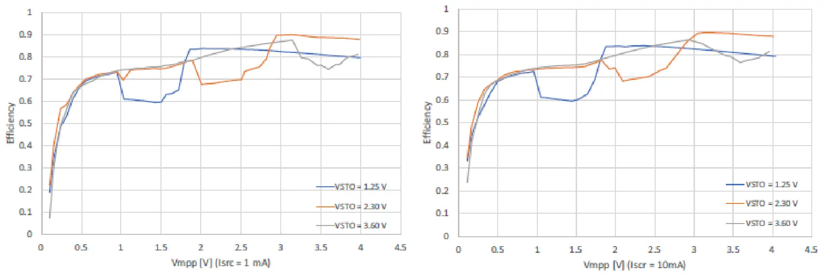
- Internal Boost efficiency Vs. input voltage in Low Power mode:
 Internal Boost efficiency Vs. input voltage in High Power mode:
 Internal Boost efficiency Vs. input voltage in High Power mode:
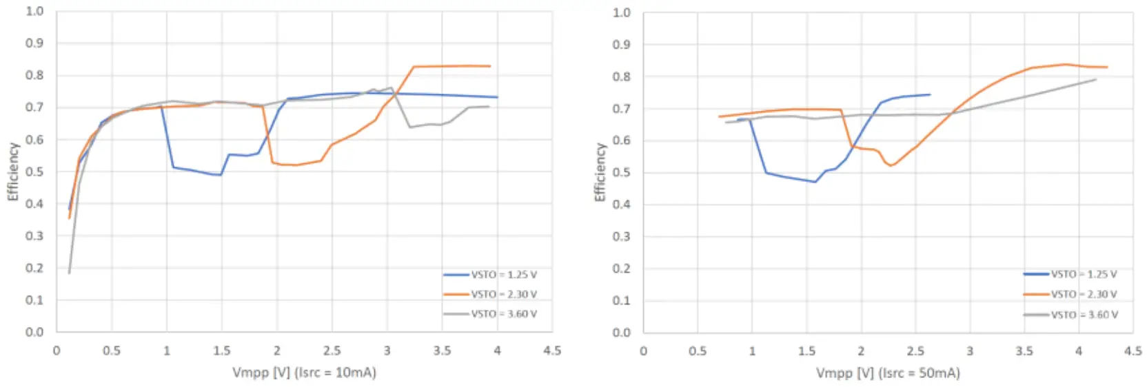
STEP 4: Check the Status
| Symbol | Logic Level | Low | High |
| Logic output pins | |||
| ST-STO | Logic output levels on the status STO pins | GND | VITO |
www.e-peas.com
© 2021 e-peas S.A.
V1.0![]()


