![]()
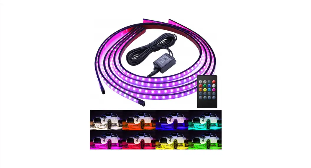
Golf Cart Underglow Kit Installation Diagram
We are striving to build a reliable brand of golf carts parts and accessories. Hope this manual can assist you with easier installation.
For more technical support, please reach us via
Website: www.10101.com
Email : [email protected]
Facebook : zhong zaiyang
Youtube: 10LOL
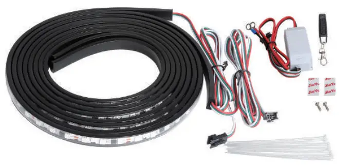
Contents………………………………………Qty
Underglow LED Light Strip…………. 2
Control Box…………………………………. 1
Cable Ties………………………………….. 15
Screws…………………………………………. 2
Remotes Control……………………….. 1
Manual……………………………………….. 1
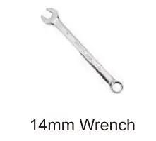
Installation Tools……………………Qty
14mm Wrench……………………………. 1
See Figure 1
Installation Tools
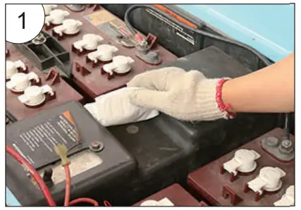
Installation Steps
- Find the right place and Wipe off the dust.
See figure 1
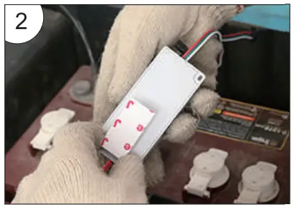
- Use double-sided tape to fix the Input Control box.
See figure 2
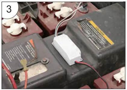
- As shown in the illustration.
See figure 3
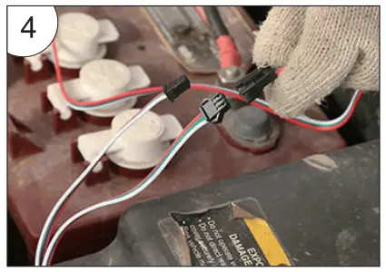
- Connect the light wire to the Input Control box.
See figure 4
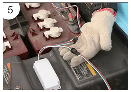
- Connect all light strips.
See figure 5
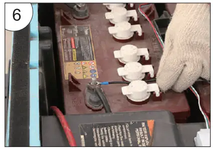
- Connect the negative terminal of the battery (black cord).
See figure 6
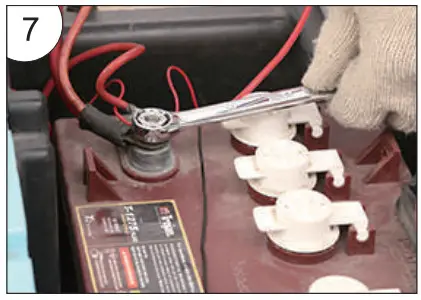
- Connect the lamp wire, and then power on.
See figure 7
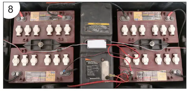
- Power supply installation diagram.
See figure 8
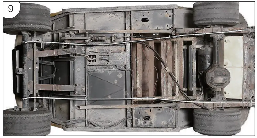
- Light strip installation diagram.
See figure 9
Wiring Diagram of Golf Cart Ribbon Light Bar.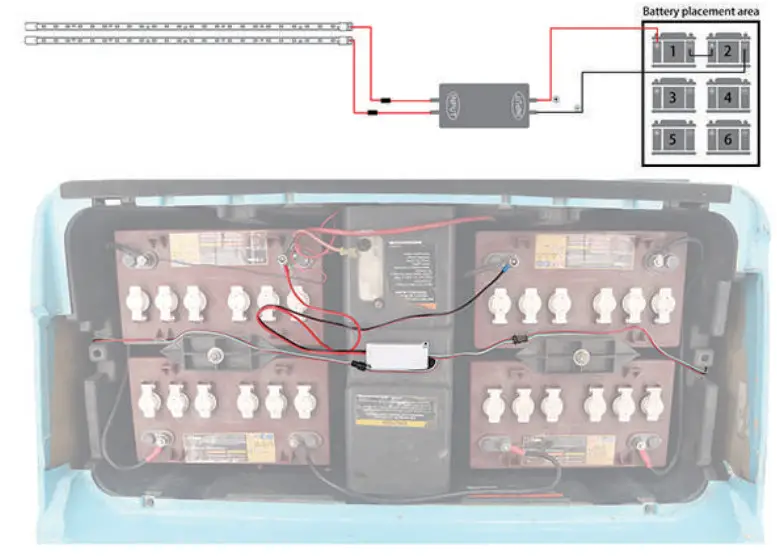
Fantastic Color Strip light Function
Button:
A: ON B: OFF C: Music Mode D: Switching Mode
Each time press button “A” to turn on, then press button “D”to switch modes.
14 Modes Selection:
- Fantastic Color Flow Mode
- Colorful Cyclic Flash Mode
- Colorful Flow Mode
- Fantastic Color Gradient Mode
- Colorful Switching to Flow Mode
- Colorful Round Flow (Flow from two ends to the middle, then back to the ends.)
- Red Gradient Mode
- Blue Gradient Mode
- Green Gradient Mode
- Pink Gradient Mode
- Light Blue Gradient Mode
- Yellow Gradient Mode
- White Gradient Mode
- Colorful Cyclic Gradient Mode
Precautions :
- Connect the lights and then power it on to test whether it works.
It can be dangerous to power on during the installation process. Please power on after installation. - Do not twist the light bar during installation to prevent the light bar from breaking or disconnection.
- When replacing the remote control or control box, press any key on the remote control to pair the remote control and the control box within 5 seconds of power on.
Troubleshooting:
- If the light turns off but occasionally turns on automatically Check: Whether there is any looseness between the power cord of the control box and the battery.
- If the light works before installation, but not after installation Check: Whether the connection port between the lamp and the main controller is loose,is the main controller and Battery have positive and negative connections.
- When the remote control does not work Check: Whether the remote control battery is charged. Then reconnect the control box, and press any key on the remote control to repair within 5 seconds of power on.
- When half of the bar lights are off or there is only one color in the seven color modes Check: Whether the light bar is twisted or damaged, if it cannot be repaired, it should be replaced.
FCC Caution:
This device complies with part 15 of the FCC Rules. Operation is subject to the following two conditions:
(1) This device may not cause harmful interference, and (2) this device must accept any interference received, including interference that may cause undesired operation.
Any changes or modifications not expressly approved by the party responsible for compliance could void the user’s authority to operate the equipment.
NOTE: This equipment has been tested and found to comply with the limits for a Class B digital device, pursuant to Part 15 of the FCC Rules. These limits are designed to provide reasonable protection against harmful interference in a residential installation. This equipment generates, uses, and can radiate radio frequency energy and, if not installed and used in accordance with the instructions, may cause harmful interference to radio communications. However, there is no guarantee that interference will not occur in a particular installation.
If this equipment does cause harmful interference to radio or television reception, which can be determined by turning the equipment off and on, the user is encouraged to try to correct the interference by one or more of the following measures:
- Reorient or relocate the receiving antenna.
- Increase the separation between the equipment and receiver.
- Connect the equipment into an outlet on a circuit different from that to which the receiver is connected.
- Consult the dealer or an experienced radio/TV technician for help.
The device has been evaluated to meet general RF exposure requirements. The device can be used in portable exposure conditions without restriction.
FCC ID: 2A6PN-A02-F79-B12


