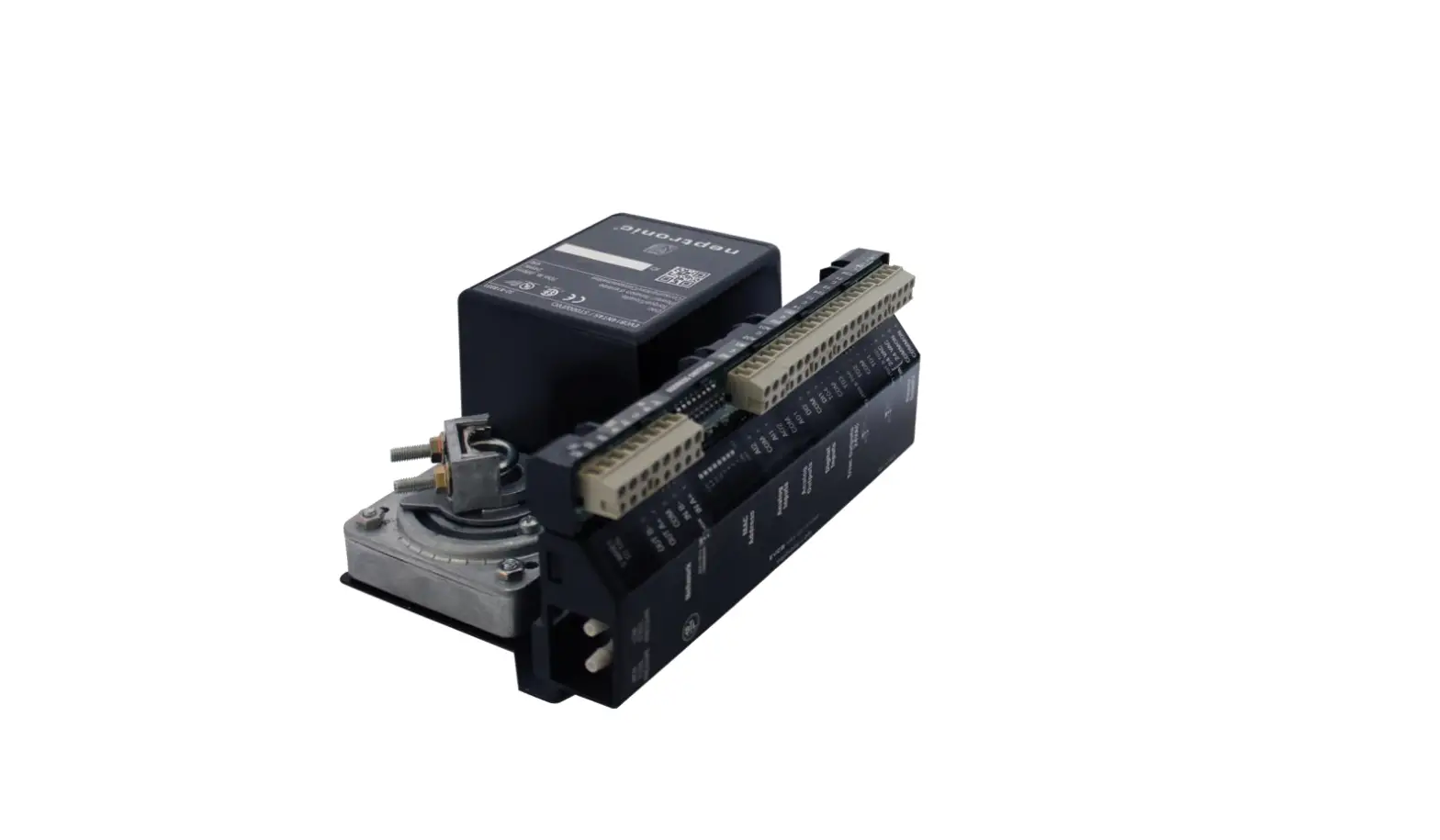
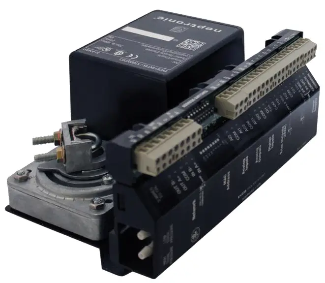
neptronic EVCB14N Series Modbus Communication Module
Introduction
The EVCB14N Series Modbus Communication Module User Guide provides information for using the Neptronic® communication feature. The controller uses Modbus communication protocol over serial line in the RTU mode and provides a Modbus network interface between client devices and Neptronic EVCB14N Series devices. The EVCB14N Series Modbus Guide assumes that you are familiar with Modbus terminology.
The following are the requirements for Modbus:
- Data Model. The EVCB Modbus server data model uses only the Holding Registers table.
- Function Codes. The EVCB Modbus server supports a limited function codes subset comprising:
- Read Holding Registers (0x03)
- Write Single Register (0x06)
- Write Multiple Registers (0x10)
- Exception Responses. The EVCB Modbus server supports the following exception codes:
- Illegal data address
- Illegal data value
- Slave device busy
- Serial Line. The EVCB Modbus over serial line uses RTU transmission mode over a two-wire configuration RS485 (EIA/TIA-485 standard) physical layer.
- The physical layer can use fixed baud rate selection or automatic baud rate detection (default) as per the Modbus Auto Baud Rate device menu item or holding register index 1.
- The supported baud rates are 9600, 19200, 38400, and 57600.
- The physical layer also supports variable parity control and stop bit configuration as per the Modbus Comport Config device menu item or holding register index 2.
- In auto baud rate configuration, if the device detects only consecutive bad frames (2 or more) for one second with any given baud rate, it will reinitialize itself to the next baud rate.
- Addressing. The EVCB device only answers at the following address:
- The device’s unique address (1 to 246) that can be set through the device menu or through holding register index 0.
Holding Registers Table
Table Glossary
| Name | Description | Name | Description |
| W | Writable Register | ASCII | For registers containing ASCII (8-bit) characters |
| RO | Read Only Register | MSB | Most Significant Byte |
| Unsigned | For range of values from 0 to 65,535, unless otherwise specified | LSB | Least Significant Byte |
| Signed | For range of values from -32,768 to 32,767, unless otherwise specified | MSW | Most Significant Word |
| Bit String | For registers with multiple values using bit mask (example, flags) | LSW | Least Significant Word |
Holding Register Table
| Register Index | Description | Data Type | Range | Writable | ||
| 40000 | Modbus Address and Product Type. | Unsigned | MSB = Product type (e.g. 111 for EVCB) LSB = Modbus Address (e.g. 1-246) | W | ||
| 40001 | MSTP Baud Rate. | Unsigned Scale 100 | 0, 9600, 19200, 38400, or 57600 0 = Auto Baud Rate Detection Value/100 (e.g. 38400 baud = 384) | W | ||
| 40002 | Modbus Slave Communication Port Configuration. | Unsigned | 1= No parity, 2 Stop bits 2= Even parity, 1 stop bit 3= Odd parity, 1 stop bit | W | ||
| 40003 | Product Name (characters 8 & 7). | ASCII | 1 to 65,535 | char 8: 0x53 = S | char 7: 0x00 = | W |
| 40004 | Product Name (characters 6 & 5). | ASCII | 1 to 65535 | char 6: 0x49 = I | char 5: 0x34 = 4 | W |
| 40005 | Product Name (characters 4 & 3). | ASCII | 1 to 65535 | char 4: 0x42 = B | char 3: 0x4E = N | W |
| 40006 | Product Name (characters 2 & 1). | ASCII | 1 to 65535 | char 2: 0x45 = E | char 1: 0x56 = V | W |
| Register Index | Description | Data Type | Range | Writable |
| 40007 | Product actual firmware version. | Unsigned | 1 to 65535 (e.g. 410) | RO |
| 40008 | Product actual EEPROM version. | Unsigned | 1 to 65535 (e.g. 203) | RO |
|
40009 |
System Status 1. |
Bit String | [B0 – B11]: Reserved B12: CO2 alarm 0 = Normal; 1 = Alarm B13: Pressure mode (actual status) 0 = Independent; 1 = Dependent B14: Air Flow 0 = Normal; 1 = Error |
RO |
|
40010 |
System Status 2. |
Bit String | [B0-B11, B13-B14]: Reserved
B12: Alarm override 0 = Normal; 1 = Alarm |
RO |
| 40011 | Internal Temperature. | Unsigned Scale 100 | 0 to 5000 Value x 100 (e.g. 23°C = 2300) | RO |
| 40012 | External Temperature. | Signed Scale 100 | -4000 to 10000 Value x 100 (e.g. 18°C = 1800) | RO |
| 40013 | Change Over Temperature. | Signed Scale 100 | -4000 to 10000 Value x 100 (e.g. 18°C = 1800) | RO |
|
40014 | Internal Humidity Internal humidity, reading of the integrated humidity sensor of TRLH or TRLGH/TDU (models with humidity sensor). If not available, the value will be fixed to 0x7FFF (32767) |
Unsigned Scale 10 |
0 to 1000 Value x 10 (e.g. 45%RH = 450) |
RO |
| 40015 | Input 3 reading, pressure sensor value (*Not available on all models) | Unsigned Scale 10 | 0 to 2500 Value x 10 (e.g. 10 Pa = 100) | RO |
| 40016 | Analog input 1 value. | Unsigned Scale 100 | 0 to 1000 Value x 100 (e.g. 2 mV = 200) | RO |
| Register Index | Description | Data Type | Range | Writable |
| 40017 | Analog Input 2 value. | Unsigned Scale 100 | 0 to 1000 Value x 100 (e.g. 3 mV = 300) | RO |
| 40018 | CO2 value in ppm If using TRLG or TRLG/TDU (models with CO2 sensor) and CO2 is in TRL mode, it is the sensor value in ppm. If using AI1 or AI2 and CO2 is set in Analog more, the reading is from the external sensor. | Unsigned Scale 100 | 100 to reg 40098 Value x 100 (e.g. 5 ppm = 500) | RO |
| 40019 | Air supply temperature. | Signed Scale 100 | -4000 to 10000 Value x 100 (e.g. 5°C = 500) | RO |
| 40020 | Control temperature. | Signed Scale 100 | -4000 to 10000 Value x 100 (e.g. 25°C = 2500) | W |
| 40021 | Heating demand for heating ramp 1. | Unsigned Scale 10 | 0 to 1000 Value x 10 (e.g. 25% = 250) | RO |
| 40022 | Cooling demand for cooling ramp 1. | Unsigned Scale 10 | 0 to 1000 Value x 10 (e.g. 25% = 250) | RO |
| 40023 | Temperature offset applied on internal temperature. | Signed Scale 100 | -500 to 500 Value x 100 (e.g. 0.5°C = 50) | W |
| 40024 | Temperature offset applied on external temperature. | Signed Scale 100 | -500 to 500 Value x 100 (e.g. 0.5°C = 50) | W |
| 40025 | Temperature setpoint used during the occupancy period of the day. | Unsigned Scale 10 | Range: 40026 to 40027 Value x 10 (e.g. 20°C = 200) | W |
| 40026 | Minimum temperature setpoint used during the day. | Unsigned Scale 10 | Range: 100 to 40027 Value x 10 (e.g. 10°C = 100) | W |
| 40027 | Maximum temperature setpoint used during the day. | Unsigned Scale 10 | Range: 40026 to 400 Value x 10 (e.g. 40°C = 400) | W |
| 40028 | Cooling setpoint during No Occupancy / Night Set Back | Unsigned Scale 10 | Range: 40029 to 400 Value x 10 (e.g. 22°C = 220) | W |
| 40029 | Heating setpoint during No Occupancy / Night Set Back | Unsigned Scale 10 | Range: 100 to 40028 Value x 10 (e.g. 16°C = 160) | W |
| Register Index | Description | Data Type | Range | Writable |
| 40030 | Cooling demand for proportional band 1. | Unsigned Scale 10 | 5 to 50 Value x 10 (e.g. 0.3°C = 3) | W |
| 40031 | Heating demand for proportional band 1. | Unsigned Scale 10 | 5 to 50 Value x 10 (e.g. 0.3°C = 3) | W |
| 40032 | Cooling dead band for proportional band 1. | Unsigned Scale 10 | 0 to 50 Value x 10 (e.g. 0.3°C = 3) | W |
| 40033 | Heating dead band for proportional band 1. | Unsigned Scale 10 | 0 to 50 Value x 10 (e.g. 0.3°C = 3) | W |
| 40034 | Changeover temperature setpoint. | Unsigned Scale 10 | 100 to 400 Value x 10 (e.g. 12°C = 120) | W |
| 40035 | Night setback override delay in minutes. | Unsigned | 0 to 180 minutes | W |
| 40036 | Integral time factor for heating in seconds. | Unsigned | 0 to 250 seconds | W |
| 40037 | Cooling anti-cycle delay: delay in minutes before activating or reactivating the cooling contact. | Unsigned | 0 to 15 minutes | W |
| 40038 | Floating time 1: Indicates the time in seconds required by the actuator to complete a 90° run. | Unsigned | 15 to 250 seconds | W |
| 40039 | Occupancy Delay Mode in minutes | Unsigned | 0 to 180 minutes | W |
| 40040 | Cooling demand for cooling ramp 2. | Unsigned Scale 10 | 0 to 1000 % Value x 10 (e.g. 30% = 300) | RO |
| 40041 | Proportional band for cooling ramp 2 | Unsigned Scale 10 | 5 to 50 Value x 10 (e.g. 0.2°C = 2) | W |
| 40042 | Dead band for cooling ramp 2. | Unsigned Scale 10 | 0 to 50 Value x 10 (e.g. 0.2°C = 2) | W |
| 40043 | Heating demand for heating ramp 2. | Unsigned Scale 10 | 0 to 1000 % Value x 10 (e.g. 30% = 300) | W |
| 40044 | Proportional band for heating ramp 2. | Unsigned Scale 10 | 5 to 50 Value x 10 (e.g. 0.2°C = 2) | W |
| Register Index | Description | Data Type | Range | Writable |
| 40045 | Dead band for heating ramp 2. | Unsigned Scale 10 | 0 to 50 Value x 10 (e.g. 0.2°C = 2) | W |
| 40046 | Changeover demand for the VAV box. | Unsigned Scale 10 | 0 to 1000 % Value x 10 (e.g. 30% = 300) | RO |
| 40047 | Changeover proportional band: the range in which the controller modulates the cooling and heating output from 0 to 100%. | Unsigned Scale 10 | 5 to 50 Value x 10 (e.g. 0.2°C = 2) | W |
| 40048 | Changeover deadband: the range at which the controller takes no action when the temperature is above or below the setpoint. | Unsigned Scale 10 | 0 to 50 Value x 10 (e.g. 0.2°C = 2) | W |
| 40049 | AO1 min Vdc: minimum voltage of analog output 1. | Unsigned Scale 10 | Range: 0 to reg. 40051 Value x 10 (e.g. 2 Volts = 20) | W |
| 40050 | AO2 min Vdc: minimum voltage of analog output 2. | Unsigned Scale 10 | Range: 0 to reg. 40052 Value x 10 (e.g. 2 Volts = 20) | W |
| 40051 | AO1 max Vdc: maximum voltage of analog output 1. | Unsigned Scale 10 | Range: reg. 40049 to 100 Value x 10 (e.g. 10 Volts = 100) | W |
| 40052 | AO2 max Vdc: maximum voltage of analog output 2. | Unsigned Scale 10 | Range: reg. 40050 to 100 Value x 10 (e.g. 10 Volts = 100) | W |
| * = The minimum and maximum voltages correspond to 0 to 100% demand. The minimum voltage is always applied to the output. The maximum voltage is applied when the demand reaches 100%. For reheat applications, we recommend to leave the minimum voltage at 0Vdc to avoid heating when the demand is 0%. | ||||
| 40053 | Time of numerical filter of delta pressure in seconds. Not effective on all models. | Unsigned | 1 to 10 seconds | W |
| 40054 | Factor of V=K*sqrt(dP), where dP = 1. Not effective on all models. | Unsigned | Range: 100 to 9995 CFM | W |
| 40055 | Minimum air flow for cooling. Not effective on all models. | Unsigned | Range: 0 or (12.7%) Kfac to reg 40056 CFM | W |
| 40056 | Maximum air flow for cooling. Not effective on all models. | Unsigned | Range: reg 40055 to reg 40054 CFM | W |
| 40057 | Minimum air flow for heating. Not effective on all models. | Unsigned | Range: 0 or (12.7%) Kfac to reg 40058 CFM | W |
| Register Index | Description | Data Type | Range | Writable |
| 40058 | Maximum air flow for heating. Not effective on all models. | Unsigned | Range: reg 40057 to reg 40054 CFM | W |
| 40059 | Integral time factor of air flow in minutes. Not effective on all models. | Unsigned | 0 to 60 minutes | W |
| 40060 | Actual air flow converted from delta pressure sensor. Not effective on all models. | Unsigned | Range: 0 to reg 40054 CFM | RO |
| 40061 | Air flow calculated from system demand. Not effective on all models. | Unsigned | Range: 0 to 9999 CFM | RO |
| 40062 | Configuration value for Air Flow Max used during airflow balancing sequence. Refer to EVCB-Airflow Balance Instructions. Not effective on all models. | Unsigned | Range: 0 to 9999 CFM | W |
| 40063 | Analog output 1 value. | Unsigned Scale 10 | Unit: Volt, Range: reg 40049 to reg 40051 Value x 10 (e.g. 5 Volts = 50) | W |
| 40064 | Analog output 2 value. | Unsigned Scale 10 | Unit: Volt, Range: reg 40050 to reg 40052 Value x 10 (e.g. 5 Volts = 50) | W |
| 40065 | Percentage of demand to close TRIAC output 1. Not available on all models. | Unsigned | 15 to 80% | W |
| 40066 | Percentage of demand to close TRIAC output 2. Not available on all models. | Unsigned | 15 to 80% | W |
| 40067 | Percentage of demand to close TRIAC output 3. Not available on all models. | Unsigned | 15 to 80% | W |
| 40068 | Percentage of demand to close TRIAC output 4. Not available on all models. | Unsigned | 15 to 80% | W |
| 40069 | Percentage of demand to open TRIAC output 1. Not available on all models. | Unsigned | 0 to reg 40065-4% | W |
| 40070 | Percentage of demand to open TRIAC output 2. Not available on all models. | Unsigned | 0 to reg 40065-4% | W |
| 40071 | Percentage of demand to open TRIAC output 3. Not available on all models. | Unsigned | 0 to reg 40065-4% | W |
| Register Index | Description | Data Type | Range | Writable |
| 40072 | Percentage of demand to open TRIAC output 4. Not available on all models. | Unsigned | 0 to reg 40065-4% | W |
| 40073 | Integral time factor for cooling in seconds. | Unsigned | 0 to 250 seconds | W |
| 40074 | Motor position. Not effective on all models. | Unsigned | 0 to 100% | RO |
| 40075 to 40080 – Reserved | RO | |||
| 40081 | Air flow offset calibration. Refer to EVCB-Airflow Balance Instructions.Not effective on all models. | Signed | -500 to 500 CFM | W |
| 40084 | Configuration value for Air Flow Min used during airflow balancing sequence. Refer to EVCB-Airflow Balance Instructions. Not effective on all models. | Unsigned | Range: 0 to 9999 CFM | W |
| 40082, 40083, and 40085 to 40095 – Reserved | RO | |||
| 40096 | Network fallback timeout Present Value in minutes. | Unsigned | 0 to 60 minutes | W |
| 40097 | Reserved | RO | ||
| 40098 | Maximum range of the CO2 sensor connected to AI1 or AI2. | Unsigned | 100 to 5000 PPM | W |
| 40099 | Maximum concentration of CO2 before the EVC activates an alarm. | Unsigned | Range: 100 to the greater ppm value between 2000 and reg 40098 | W |
| Register Index | Description | Data Type | Range | Writable | |
| B3, B13-B14: Reserved | B7: Freeze protection 0 = Disabled; 1 = Enabled | ||||
| B0: Tstat temperature units 0 = Celsius; 1 = Fahrenheit
B1: Modbus temperature units 0 = Celsius; 1 = Fahrenheit | B8: User system off mode 0 = User can set Tstat to OFF 1 = User cannot set Tstat OFF | ||||
|
40100 |
System Option 1. F Not effective on all models. |
Bit String | B2: Temperature setpoint lock 0 = Unlocked; 1 = Locked
B4: TO1/TO2 floating directionF 0 = Direct; 1 = Reverse | B9: Keypad bottom left lock 0 = Unlocked; 1 = Locked
B10:Keypad upper left lock 0 = Unlocked; 1 = Locked
B11: Keypad arrows lock 0 = Unlocked; 1 = Locked |
W |
| B5: TO3/TO4 floating directionF 0 = Direct; 1 = Reverse | B12: Program lock 0 = Unlocked; 1 = Locked | ||||
| B6: Onboard motor directionF 0 = Direct; 1 = Reverse | B15: Schedule 0 = Disabled; 1 = Enabled | ||||
| Register Index | Description | Data Type | Range | Writable | |
| B0-B1, B13: Reserved | B8: TO3 directionF 0 = Direct; 1 = Reverse | ||||
| B2: Auto baud rate detection 0 = Enabled; 1 = Disabled | B9: TO4 directionF 0 = Direct; 1 = Reverse | ||||
|
40101 | System Option 2. Notes B14: Applies only if DI2 is in OverHeat or Override. B15: Configuration value of the fan operation when an output ramp is configured with the option “Fan On”. When set to (0) On, the fan is continuously in operation even when EVC is off. When set to (1) Off, the fan turns off during the following conditions; User System Mode is set to OFF, when in night setback mode, scheduler forces the EVC OFF or when Digital Input 2 is set to Override and is active. F Not effective on all models. |
Bit String | B3: Night setback mode 0 = Tstat ON; 1 = Tstat OFF
B4: AO1 direction 0 = Direct; 1 = Reverse
B5: AO2 direction 0 = Direct; 1 = Reverse
B6: TO1 directionF 0 = Direct; 1 = Reverse
B7: TO2 directionF 0 = Direct; 1 = Reverse | B10: Display RHF 0 = No; 1 = Yes
B11: Pressure mode selectF 0 = independent;1 = dependent
B12: Auto pressure modeF change 0 = Enabled; 1 = Disabled
B14: DI 2 Contact 0: NO; 1: NC |
W |
| B15: Fan always “on” mode 0 = Always on; 1 = Follow NSB/NoOcc | |||||
| 40102 | Status value of the actual changeover control mode. | Unsigned | 0 = Cooling, 1= Heating | RO | |
| 40103 | System command status. F Not effective on all models. | Unsigned | 0 = No Command, 1 = AirFlow 1 Balancing, 4 = AirFlow 2 Balancing | W | |
| 40104 | TO OnOff. * Not available on all models. | Unsigned | 1 = TO1 OnOff 2 = TO2 OnOff | 4 = TO3 OnOff 8 = TO4 OnOff | RO |
| 40105 | Occupancy or night setback mode commands. | Unsigned | 1 = Locally 2 = Off 3 = Occupancy | 4 = NoOccupancy 5 = Day 6 = Night | W |
| 40106 | Status of digital input 1. | Unsigned | 0 = Open, 1 = Close | RO | |
| Register Index | Description | Data Type | Range | Writable | |
|
40107 |
Analog input 1 signal. * Not available on all models. F Not effective on all models. ** Only available with EVCB14NIT0S. |
Unsigned | 1 = OFF 2 = ETS (external temp) 3 = SENS (changeover sensor) 4 = NoCL (normally cool) 5 = NoHT (normally heat) 6 = STFL* (setpnt airflow 0-10Vdc) 7 = CO2 (carbon dioxide) 8 = AST (air supply temp sensor) 9 = morF (motor position) | 10 = EXT50K** (external 50KΩ sensor) 11 = TSTAT temp sensor** (thermostat temperature sensor) 12 = TSTAT Setpoint** (thermostat setpoint 0-10Vdc) 13 = TSTAT Setpoint 2-10V** (thermostat setpoint 2-10Vdc) |
W |
| 40108 | User System Control Mode. | Unsigned | 1 = AUTO 2 = HEAT | 3 = COOL 4 = OFF | W |
| 40109 | Sets the permissions or restrictions to change the system control mode by the user. | Unsigned | 1 = AUTO 2 = HEAT | 3 = COOL 4 = COOL-HEAT 5 = AUTO-LOCK | W |
| 40110 | Indicates the status of the Night Setback mode. | Unsigned | 1 = Day, 2 = Night, 3 = Derogation | RO | |
| 40111 | Configuration of DI1 mode. Night setback or no occupancy status. * Only available with EVCB14NIT0S. | Unsigned | 1=Off 2= Occupancy NO 3= Occupancy NC | 4= Night Set Back NO 5= Night Set Back NC 6= Unoccupancy damper* | W |
|
40112 |
Analog input 2 signal. * Not available on all models. ** Only available with EVCB14NIT0S. |
Unsigned | 1 = OFF 2 = ETS (external temp) 3 = SENS (changeover sensor) 4 = NoCL (normally cool) 5 = NoHT (normally heat) 6 = STFL* (setpnt airflow 0-10Vdc) 7 = CO2 (carbon dioxide) 8 = AST (air supply temp sensor) 9 = mor (motor position) | 10 = EXT50K** (external 50KΩ sensor) 11 = TSTAT temp sensor** (thermostat temperature sensor) 12 = TSTAT Setpoint** (thermostat setpoint 0-10Vdc) 13 = TSTAT Setpoint 2-10V** (thermostat setpoint 2-10Vdc) |
W |
| 40113 | Occupancy status of the zone. | Unsigned | 1 = No Occupancy, 2 = Occupancy, 3 = Derogation | RO | |
|
40114 | AO1: Analog output 1 control ramp Notes: Options 11 and 12 are for fan powered applications and only available with models: EVCB14NIT4S, EVCB14NDT4S, and EVCB14NIT4SF. * Not available on all models. |
Unsigned | 1 = OFF 2 = CR1 (cooling ramp 1) 3 = CR2 (cooling ramp 2) 4 = HR1 (heating ramp 1) 5 = HR2 (heating ramp 2) 6 = ArFL (airflow reading) | 7 = CO2 (carbon dioxide) 8 = STFL* (setpnt airflow 0-10Vdc) 9 – 10 = reserved 11 = Fan Auto (follow demand) 12 = Fan On (always on) |
W |
| Register Index | Description | Data Type | Range | Writable | |
|
40115 | AO2: Analog output 2 control ramp Notes: Options 11 and 12 are for fan powered applications and only available with models: EVCB14NIT4S, EVCB14NDT4S, and EVCB14NIT4SF. * Not available on all models. |
Unsigned | 1 = OFF 2 = CR1 (cooling ramp 1) 3 = CR2 (cooling ramp 2) 4 = HR1 (heating ramp 1) 5 = HR2 (heating ramp 2) 6 = ArFL (airflow reading) | 7 = CO2 (carbon dioxide) 8 = STFL* (setpnt airflow 0-10Vdc) 9 – 10 = reserved 11 = Fan Auto (follow demand) 12 = Fan On (always on) |
W |
|
40116 | TO1: Configuration of the ramp used to modulate (pulse or floating) or activate/deactivate (On/Off) TO1 based on demand. * Not available on all models. |
Unsigned | 1 = OFF 2 = CR1 (cooling ramp 1) 3 = CR2 (cooling ramp 2) 4 = HR1 (heating ramp 1) 5 = HR2 (heating ramp 2) 6 = CO2 (carbon dioxide) | 7 = STFL* (setpnt airflow 0-10Vdc) 8 = COR* (changeover ramp) 9 = CH1* (cool/heat 1) 10 = ANLG* (analog 0-10Vdc) 11 = Fan Auto (follow demand) 12 = Fan On (always on) |
W |
|
40117 | TO2: Configuration of the ramp used to modulate (pulse or floating) or activate/deactivate (On/Off) TO2 based on demand. * Not available on all models. |
Unsigned | 1 = OFF 2 = CR1 (cooling ramp 1) 3 = CR2 (cooling ramp 2) 4 = HR1 (heating ramp 1) 5 = HR2 (heating ramp 2) 6 = CO2 (carbon dioxide) | 7 = STFL* (setpnt airflow 0-10Vdc) 8 = COR* (changeover ramp) 9 = CH1* (cool/heat 1) 10 = ANLG* (analog 0-10Vdc) 11 = Fan Auto (follow demand) 12 = Fan On (always on) |
W |
|
40118 | TO3: Configuration of the ramp used to modulate (pulse or floating) or activate/deactivate (On/Off) TO3 based on demand. * Not available on all models. |
Unsigned | 1 = OFF 2 = CR1 (cooling ramp 1) 3 = CR2 (cooling ramp 2) 4 = HR1 (heating ramp 1) 5 = HR2 (heating ramp 2) 6 = CO2 (carbon dioxide) | 7 = STFL* (setpnt airflow 0-10Vdc) 8 = COR* (changeover ramp) 9 = CH1* (cool/heat 1) 10 = ANLG* (analog 0-10Vdc) 11 = Fan Auto (follow demand) 12 = Fan On (always on) |
W |
|
40119 | TO4: Configuration of the ramp used to modulate (pulse or floating) or activate/deactivate (On/Off) TO4 based on demand. * Not available on all models. |
Unsigned | 1 = OFF 2 = CR1 (cooling ramp 1) 3 = CR2 (cooling ramp 2) 4 = HR1 (heating ramp 1) 5 = HR2 (heating ramp 2) 6 = CO2 (carbon dioxide) | 7 = STFL* (setpnt airflow 0-10Vdc) 8 = COR* (changeover ramp) 9 = CH1* (cool/heat 1) 10 = ANLG* (analog 0-10Vdc) 11 = Fan Auto (follow demand) 12 = Fan On (always on) |
W |
| 40120 | TO1: Signal output type for TRIAC output 1. * Not available on all models. | Unsigned | 3 = Pulsing, 4 = On_Off, 5 = Floating | W | |
| 40121 | TO2: Signal output type for TRIAC output 2. * Not available on all models. | Unsigned | 3 = Pulsing, 4 = On_Off | W | |
| 40122 | TO3: Signal output type for TRIAC output 3. * Not available on all models. | Unsigned | 3 = Pulsing, 4 = On_Off, 5 = Floating | W | |
| Register Index | Description | Data Type | Range | Writable | |||
| 40123 | TO4: Signal output type for TRIAC output 4. * Not available on all models. | Unsigned | 3 = Pulsing 4 = On_Off | W | |||
| 40124 | Pressure independent output selection for VAV damper actuator. * Not available on all models. | Unsigned | 3 = Floating1, 4 = Floating2, 5 = Motor | W | |||
|
40125 | Motor ramp: Configuration of the ramp used to modulate the actuator based on demand. * Not available on all models. |
Unsigned | 2 = CR1 (cooling ramp 1) 3 = CR2 (cooling ramp 2) 4 = HR1 (heating ramp 1) 5 = HR2 (heating ramp 2) 6 = Not Available | 7 = STFL* (setpnt airflow 0-10Vdc) 8 = COR (changeover ramp) 9 = CH1 (cool/heat 1) 10 = ANLG (analog 0-10Vdc) |
W | ||
| 40126 | Changeover control mode status that indicates the source of changeover values. | Unsigned | 1 = Local, 2 = Cooling, 3 = Heating | W | |||
| 40127 | Reserved | RO | |||||
| 40128 | Reserved | RO | |||||
| 40129 | Configuration of DI2 mode. * Only available with EVCB14NIT0S. | Unsigned | 1=Off 2=Override 3=OverHeat1 | 4=OverHeat2 5=OverHeatAll 6=ChangeOverNoCooling | 7=ChangeOverNoHeating 8=Unoccupancy damper* | W | |
| 40130 | Selected temperature control source (in Programming mode). | Unsigned | 1 = Internal Temperature 2 = External Temperature 3 = Remote Temperature | 4 = Average Temperature 5 = Maximum Temperature | W | ||
| 40131 | Airflow balance mode enter the balancing mode to adjust air flow factor. FNot effective on all models. | Unsigned | 1 = Close 2 = Minimum Flow | 3 = Maximum Flow 4 = Full Open | W | ||
| 40132 | Reserved | RO | |||||
| 40133 | Configuration to set the motor position in night setback mode. F Not effective on all models. | Unsigned | 1 = Auto 2 = Open | W | |||
| 40134 | Digital input 2 delay in seconds. | Unsigned | 0 to 3600 seconds | W | |||
| 40135 | Time in seconds required by the actuator to complete a 90° run. * Not available on all models. | Unsigned | 15 to 250 seconds | W | |||
| 40136 | Minimum motor position in percentage of stroke for cooling. * Not available on all models. | Unsigned | 0 to 100% | W | |||
| Register Index | Description | Data Type | Range | Writable |
| 40137 | Minimum motor position in percentage of stroke for heating. * Not available on all models. | Unsigned | 0 to 100% | W |
| 40138 | Airflow Hysteresis Stop in percentage.* Not available on all models. | Unsigned | 1 to 100% | W |
| 40139 | Airflow Hysteresis Start in percentage.* Not available on all models. | Unsigned | reg 40138 to 100% | W |
| 40140 | Airflow scale.*Not available on all models. | Unsigned | 1 = Scale1, 2 = Scale10, 3 = Scale100 | W |
| 40141 | Airflow fault deadband in percentage.* Not available on all models. | Unsigned | 1 to 30% | W |
| 40142 | Airflow fault error in percentage.* Not available on all models. | Unsigned | 0 to 100% | W |
| 40143 | Airflow fault hysteresis in percentage.* Not available on all models. | Unsigned | 1 to 30% | W |
| 40144 | Airflow fault time.*Not available on all models. | Unsigned | 2 to 59 minutes | W |
| 40145 | CL_HT SwitchTimer, waiting time before switching between the heating and cooling modes. | Unsigned | 0 to 120 minutes | W |
| 40146 | CL_HT SwitchTimerCount, countdown to indicate the swap between heating and cooling modes. | Unsigned | 0 to 4,294,967,295 seconds | RO |
| 40147 | FloatingTO1/TO2, TRIAC output 1 or 2 when set to floating, indicates the floating signal demand. * Not available on all models. | Unsigned Scale 10 | 0 to 1000% Value x 10 (e.g. 15% =150) | RO |
| 40148 | FloatingTO3/TO4, TRIAC output 3 or 4 when set to floating, indicates the floating signal demand. * Not available on all models. | Unsigned Scale 10 | 0 to 1000% Value x 10 (e.g. 15% =150) | RO |
| 40149 | TO1 Pulsing, TRIAC output 1 when set to Pulsed, indicates the pulse signal demand. * Not available on all models. | Unsigned Scale 10 | 0 to 1000% Value x 10 (e.g. 15% =150) | RO |
| 40150 | TO2 Pulsing, TRIAC output 2 when set to Pulsed, indicates the pulse signal demand. * Not available on all models. | Unsigned Scale 10 | 0 to 1000% Value x 10 (e.g. 15% =150) | RO |
| 40151 | TO3 Pulsing, TRIAC output 3 when set to Pulsed, indicates the pulse signal demand.* Not available on all models. | Unsigned Scale 10 | 0 to 1000% Value x 10 (e.g. 15% =150) | RO |
| 40152 | TO4 Pulsing, TRIAC output 4 when set to Pulsed, indicates the pulse signal demand.* Not available on all models. | Unsigned Scale 10 | 0 to 1000% Value x 10 (e.g. 15% =150) | RO |
| Register Index | Description | Data Type | Range | Writable | |
| 40153 | Over heat status. | Unsigned | 1 = OverHeatNormal 2 = OverHeat1 | 3 = OverHeat2 4 = OverHeatAll | RO |
|
40154 | Configuration to override the motor position. * Not available on all models. |
Unsigned | 1 = Auto 2 = Open 3 = Close | 4 = AirFlowCoolMin 5 = AirFlowCoolMax |
W |
| 40155 | Information displayed on the TRL/TDU. | Unsigned | 1 = Temp Demand 2 = Setpoint Demand 3 = Temp | 4 = Setpoint 5 = Off | W |
| 40156 | Status of digital input 2. | Unsigned | 0 = Open, 1 = Close | RO | |
| 40157 | Reserved | RO | |||
| B7: Occupancy Control Source | |||||
| [B0-B1, B4-B6, B8, B11-B15]: Reserved | 0 = BI1; 1 = Intern Sensor | ||||
| 40158 | System Options 3 | Bit String | B2: CO2 Display 0 = No; 1 = Yes | B9: Motor Position Control Temperature Fault 0 = Close; 1 = Open | W |
| B3: CO2 Control Source | B10: CO2 Control Mode | ||||
| 0 = Analog; 1 = TRLG | 0 = Open; 1 = Control ramp | ||||
| 40159 | System Options 4 | Bit String | [B0 – B15]: Reserved | RO | |
| 40160 | Internal CO2, reading of the integrated CO2 sensor of TRLG or TRLGH/TDU (models with humidity sensor). If not available, the value will be fixed to 0x7FFF (32767) | Unsigned | 0 to 2000 ppm | RO | |
| 40161 | Internal light sensor reading in Luxes. | Unsigned | 0 to 16000 Luxes | RO | |
| 40162 | Internal VOC sensor reading in ppb. | Unsigned | 1 to 60000 ppb | RO | |
| Register Index | Description | Data Type | Range | Writable | |
| 40163 | Internal PIR sensor reading. | Unsigned | 0 = NoOccupancy, 1 = Occupancy | RO | |
| 40164 | Occupancy minimum time in minutes. | Unsigned | 0 to 240 minutes | W | |
| 40165 | Configuration value of the minimum position in cooling/heating mode in %. | Unsigned | 0 to 100 % | W | |
| 40166 | Control SetPoint. | Unsigned Scale 1 | 10 to 40 Value x 1 (e.g. 30°C = 30) | RO | |
| 40167 | CO2 ramp proportional band | Unsigned Scale 1 | 50 to 250 ppm Value x 1 (e.g. 50ppm = 50) | W | |
| 40168 | CO2 ramp dead band | Unsigned Scale 1 | 10 to 50 ppm Value x 1 (e.g. 50ppm = 50) | W | |
| 40169 | Temperature sensor combination | Unsigned | 1 = TSTAT+AI1 2 = TSTAT+AI2 | 3 = TSTAT+AI1+AI2 4 = AI1+AI2 | W |
| 40170 | Average temperature | Signed Scale 100 | -4000 to 10000 Value x 100 (e.g. 5°C = 500) | RO | |
| 40171 | Maximum temperature | Signed Scale 100 | -4000 to 10000 Value x 100 (e.g. 5°C = 500) | RO | |
| 40172 | External sensor value of analog input 2 | Signed Scale 100 | -4000 to 10000 Value x 100 (e.g. 5°C = 500) | RO | |
400 Lebeau blvd, Montreal, Qc, H4N 1R6, Canada
neptronic.com
Toll-free in North America: 1-800-361-2308
Tel.: (514) 333-1433
Fax: (514) 333-3163
Customer service fax: (514) 333-1091
Monday to Friday: 8:00am to 5:00pm (Eastern time)


