![]() ENGINEERING
ENGINEERING
TOMORROW
Installation Guide
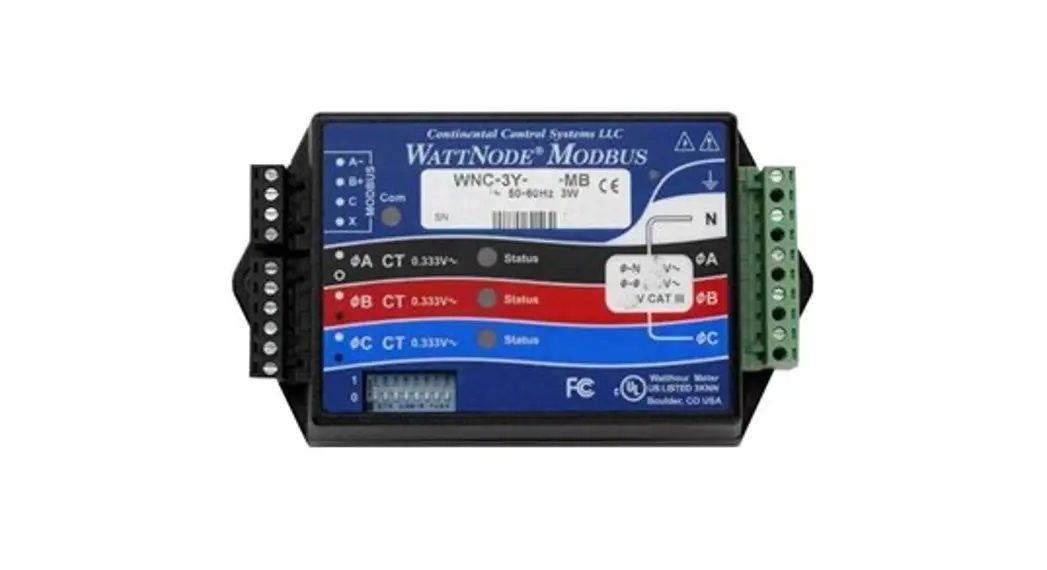
Watt Node Modbus
Type WND-WR-MB opt 38K, EP
WND-WR-MB opt 38K Watt Node Modbus
–40 – +80 °C (–40 – 176 °F)
Operating Humidity: non-condensing, 5 – 90% relative humidity (RH) up to 40 °C, decreasing linearly to 50% RH at 55 °C.
L × W × H:
155 mm × 85 mm × 38 mm (6.1” × 3.35” × 1.5”)
Mounting holes:
center-to center 136.6 mm (5.375 in)
CT:
0,333 V AC at rated current
![]()
| Code | Electrical Service Type (Load type) | Line-to-Neutral (V AC) | Line-to-Line (V AC) | Meter Powered by |
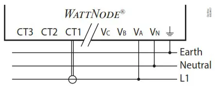
| 080Z2129 | Single Phase 2-wire with neutral | 96 – 347 | 120 – 600 | Line to Neutral or Line to Line |
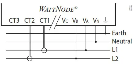
| Single Phase 3-wire with neutral | 96 – 347 | 120 – 600 | Line to Neutral or Line to Line | |
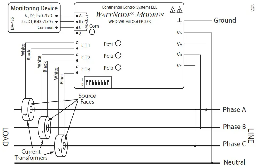
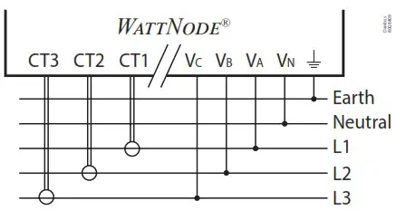
| Three Phase 4-wire wye (star) with neutral | 96 – 347 | 120 – 600 | Line to Neutral or Line to Line |
| Single Phase 2-wire with neutral | Single Phase 3-wire with neutral | Three Phase 4-wire Wye (star) with neutral |
 |  |  |
Modbus address
| DIP Switch | 1 | 2 | 3 | 4 | 5 | 6 |
| Up (1) Value | 1 | 2 | 4 | 8 | 16 | 32 |
| Address | Examples | |||||
| 1 | Up | Down | Down | Down | Down | Down |
| 1+2+4 = 7 | Up | Up | Up | Down | Down | Down |
| 4+16 = 20 | Down | Down | Up | Down | Up | Down |
| 1+2+16+32 = 51 | Up | Up | Down | Down | Up | Up |
Modbus integration with the AK-SM 800A
Step 1: Set the Modbus address
Step 2: Perform a network scan from the AK-SM 800A*
*For more information about data communication see document RC8AC and the AK-SM 800A manual. Pay special attention to the AK-SM 800A manual if devices with a different baud rate than 38.400 baud are connected to the AK-SM 800A, e.g. the variable speed compressor type SLV.
Phase Status LED
| All/ Single phase | LED Indication | Description |
| All | Red, Yellow, Green for 3 x 1 second | Power up sequence |
| All | Red / Green continuous flashing | Overvoltage warning. Line voltage too high. DISCONNECT power immediately! |
| All | OFF | Watt Node not operating. Check that the wiring and voltages are correct |
| All | Red for 3 seconds or more | Watt Node Error. If you see this happen repeatedly, replace the meter |
| Single | Green | No power but line voltage is present on this phase |
| Single | OFF | No voltage on this phase |
| Single | Red continuous flashing | Negative power on this phase (Re-versed CT’s, swapped CT wires or CT not matching line voltage phase) |
| Single | Flashing Green | Positive power on this phase |
Modbus Com LED
| LED Indication | Description |
| Green flash | Valid packet for this device |
| Yellow flash | Valid packets for different device |
| Red for 1 second | Invalid packet (bad baud rate, noise, …) |
| Red / Yellow continuous flashing | Possible address conflict (two devices with same address) |
| Red | Address set to 0 (zero) |
Precautions
- Only qualified personnel or licensed electricians should install the Watt Node meter. The mains voltages can be lethal!
- Follow all applicable local and national electrical and safety codes.
- The terminal block screws are not insulated. Do not contact metal tools to the screw terminals if the circuit is live!
- Verify that circuit voltages and currents are within the proper range for the meter model.
- Use only UL listed or UL recognized current transformers (CTs) with built-in burden resistors, that generate 0.333 Vac (333 millivolts AC) at rated current. Do not use current output (ratio) CTs such as 1 amp or 5 amp output CTs: they will destroy the meter and may create a shock hazard.
- Protect the line voltage phase conductors, typically #14 or #12 AWG with 3 pole 15 A or 20 A breaker. Depending on location, breaker may provide disconnect means.
- Equipment must be disconnected from the HAZARDOUS LIVE voltages before access.
- If the meter is not installed correctly, the safety protections may be impaired.
AN430921567693en-000101
© Danfoss | Climate Solutions | 2022.10


