![]()
Name:UWPMM1UL2X
FCC ID:SNJWLM
IC: 7118D-WLM
UWPM
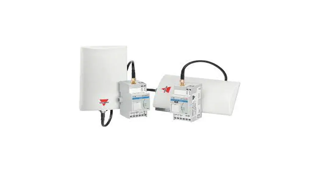
Master concentrator gateway
Instruction manual
UWPM is a master concentrator gateway that permits UWP 3.0 to gather data from multiple UWPA. This allows for the setting up and operating of a secure and robust wireless data network in the ISM band.
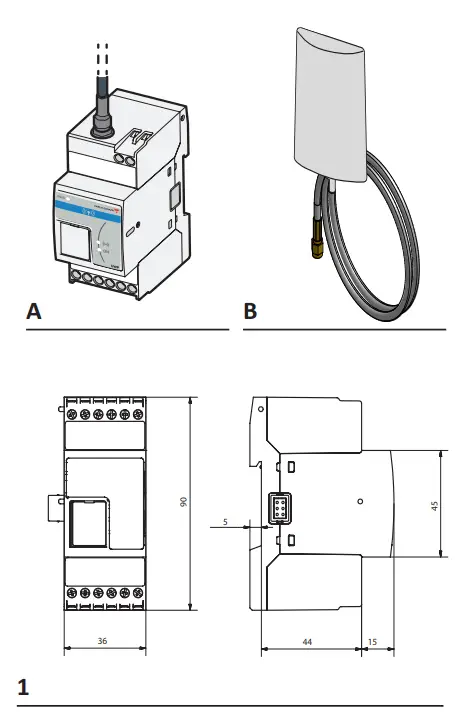 |  |
COMPONENTS
| Element | Description |
| A | UWPM |
| B | Antenna (2 m cable) |
FEATURES
General features
| Material | Noryl |
| Protection degree | Terminals: IP20 Front: IP50 |
| Mounting | On DIN rail |
| Dimensions | See picture 1 |
| Environmental specifications | |
| Operating temperature | From -25 to +55 °C |
| Storage temperature | From -30 to +70 °C |
| Power supply | |
| Power supply | From 115 to 240 V ac 24 V dc |
| Consumption | DC: 1.3 W max. AC: 5.5 VA max. |
| Connector | Screw terminals |
| LED | |
| Colour | Description |
| Green | Power supply |
| Yellow | HSBus |
| Blue | LoRa® RF technology communication |
| HSBus port | |
| Bus type | RS485 high-speed bus |
| Protocol | Internal proprietary protocol |
| Number of slaves | Max 3 per UWP 3.0 |
| Connection type | By local bus (left and right connectors) or terminals GND, A(-), B(+) T1, T2: terminal ratio inputs |
| Wireless communication | |
| Protocol | LoRa® (private UWP network in combination with UWPA) |
| Frequency | EU 868 MHz ISM band |
| Encryption | Embedded end-to-end AES128 encryption |
| Antenna | Included high-performance antenna (SMA connector, cable length 2m) |
| Diagnostics | Signal strength UWPA status |
| UWPA number | Maximum: 50 UWPA per UWPM. The number may change according to the transmission interval and the interferences |
Note: to guarantee reliable communication, install a maximum of three UWP3.0 systems with UWPM gateways close to each other.
General warnings![]() The installation of the device is strictly reserved for persons who know how to useit safely.
The installation of the device is strictly reserved for persons who know how to useit safely.![]() This manual is an integral part of the product. It should be consulted for all situations tied to installation and use. It must be kept in good condition and in a clean location accessible to all operators.
This manual is an integral part of the product. It should be consulted for all situations tied to installation and use. It must be kept in good condition and in a clean location accessible to all operators.
NOTICE: no one is authorized to open the device. This operation is reserved exclusively for CARLO GAVAZZI technical service personnel.
Compatibility
UWPM is compatible UWP 3.0 and UWPA.
MAINTENANCE AND DISPOSAL
Cleaning
Clean UWPM with a soft cloth. Do not use abrasives or solvents.
Responsibility for disposal The product must be disposed of at the relative recycling centers specified by the government or local public authorities. Correct disposal and recycling will contribute to the prevention of potentially harmful consequences to the environment and persons
Configure UWP 3.0 and UWPM to gather data from UWPA
- Configure UWPA devices and export the .zip file for integration into UWP 3.0.
- Connect UWPM to UWP 3.0 (see the relevant procedure).
- Add UWPM into the configuration by using the Tool.
Note: by adding more UWPM devices, it is possible to connect more UWPA devices. - From UWP 3.0 Tool, import the .zip file.
- Select the desired devices and variables.
- Send the configuration to UWP 3.0.
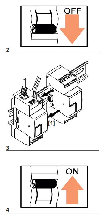
Connect UWPM to UWP 3.0
- Turn the UWP 3.0 off (picture 2).
- Connect the two devices (see picture 3).
- Connect the antenna and fix it by using the included support.
- Connect the power cables.
- Turn on (picture 4).
| Colour | LED status | Description |
|
Green | ON | Power supply OK |
| OFF | No Power supply | |
| Fast blinking | Hardware failure | |
| Yellow | ON | HS Bus communication in progress without errors |
| OFF | HS Bus communication error | |
| Fast blinking | ||
|
Blue | Single blink | The received message is valid |
| Fast blinking | The received message is not valid or has been sent by a UWPA not included in the configuration | |
| Slow blinking | Confirmation of message reception (acknowledge transmission) or reply to the joint request. |
![]() UCS desktop (Windows 7 or later) www.productselection.net/Download/UK/ucs.zip
UCS desktop (Windows 7 or later) www.productselection.net/Download/UK/ucs.zip
RED declaration of conformity www.productselection.net/MANUALS/UK/RED_declaration.pdf
 2011/65/EU (RED)
2014/30/EU (EMC – Electro Magnetic Compatibility)
Immunity: EN61000-6-2
Emissions: EN61000-6-3
FCC COMPLIANCE STATEMENT:
Changes or modifications not expressly approved by the party responsible for compliance could void the user’s authority to operate the equipment.
This device complies with part 15 of the FCC Rules.
Operation is subject to the following two conditions:
1. This device may not cause harmful interference.
2. This device must accept any interference received, including interference that may cause undesired operation.
This radio transmitter has been approved by the FCC to operate with the antenna types listed below with the maximum permissible gain indicated. Antenna types not included in this list, having a gain greater than the maximum gain indicated for that type, are strictly prohibited for
use with this device.
| Interface and frequency range | Type | Max Gain |
| LoLRoaR(a90(39.002-.391-29.61M1.H9z)MHz) | Dipole Antenna | +2.15 dB |
This device complies with the FCC RF exposure limits and has been evaluated in compliance with mobile exposure conditions.
The equipment must be installed and operated at a minimum distance of 20 cm from the human body.
Note: This equipment has been tested and found to comply with the limits for a Class B digital device, pursuant to part 15 of the FCC Rules. These limits are designed to provide reasonable protection against harmful interference in a residential installation. This equipment generates,
uses, and can radiate radio frequency energy and, if not installed and used in accordance with the instructions, may cause harmful interference to radio communications. However, there is no guarantee that interference will not occur in a particular installation. If this equipment does
cause harmful interference to radio or television reception, which can be determined by turning the equipment off and on, the user is encouraged to try to correct the interference by one or more of the following measures:
- Reorient or relocate the receiving antenna.
- Increase the separation between the equipment and receiver.
- Connect the equipment into an outlet on a circuit different from that to which the receiver is connected.
- Consult the dealer or an experienced radio/TV technician for help.
SUPPLIER’S DECLARATION OF CONFORMITY:
![]()
This device complies with part 15 of the FCC Rules. Operation is subject to the following two conditions: (1) This device may not cause harmful interference, and (2) this device must accept any interference received, including interference that may cause undesired operation. We,
Carlo Gavazzi controls Spa
Via Safforze 8, Belluno
IT-32100 ITALY
www.gavazziautomation.com
hereby declare that the equipment bearing the model name specified below was tested conforming to the applicable FCC Rules and Regulations Title 47 Part 15 under the most accurate measurement standards possible and that all the necessary steps have been taken and are in force to assure that the production units of the same equipment will continue to comply with the Commission’s requirements.
Unique Identifier:
Type of product: Wireless endpoint gateway
Brand name: Carlo Gavazzi
Model name: UWPAM1US1L2X
FCC ID: SNJWLA
IC: 7118D-WLA
Name: UWPMM1UL2X
FCC ID: SNJWLM
IC: 7118D-WLM
Responsible Party – U.S. Contact Information Company:
Carlo Gavazzi Inc.
750 Hastings Lane,
Buffalo Grove, IL 60089, USA
Tel: +1 847 465 6100
Fax: +1 847 465 7373
[email protected]
2020-11-02 | 8021879 | COPYRIGHT ©2020
CONFORMITY
ISED COMPLIANCE STATEMENTS
Changes or modifications not expressly approved by the party responsible for compliance could void the user’s authority to operate the equipment.
This device complies with ISED license-exempt RSS(s).
Operation is subject to the following two conditions:
1. This device may not cause harmful interference.
2. This device must accept any interference received, including interference that may cause undesired operation.
This radio transmitter has been approved by the ISED to operate with the antenna types listed below with the maximum permissible gain indicated. Antenna types not included in this list, having a gain greater than the maximum gain indicated for that type, are strictly prohibited for use with this device.
| Interface et bandes des fréquences | Type | Max Gain |
| L LLooRRaa((990032..03–991121.6.9MMHzH) z) | Dipole Antenna | +2.15 dB |
This device complies with ISED RF exposure limits and has been evaluated in compliance with mobile exposure conditions.
The equipment must be installed and operated at a minimum distance of 20 cm from the human body.
This Class B digital apparatus complies with Canadian ICES-003.
IFT COMPLIANCE STATEMENTS
2020-11-02 | 8021879 | COPYRIGHT ©2020
 http://www.productselection.net/
CARLO GAVAZZI Controls SpA
via Safforze, 8 32100 Belluno (BL) Italy
www.gavazziautomation.com
[email protected]
info: +39 0437 355811 / fax: +39 0437 355880![]() 2019-08-29 | 8021966 | COPYRIGHT ©2019
2019-08-29 | 8021966 | COPYRIGHT ©2019


