![]()
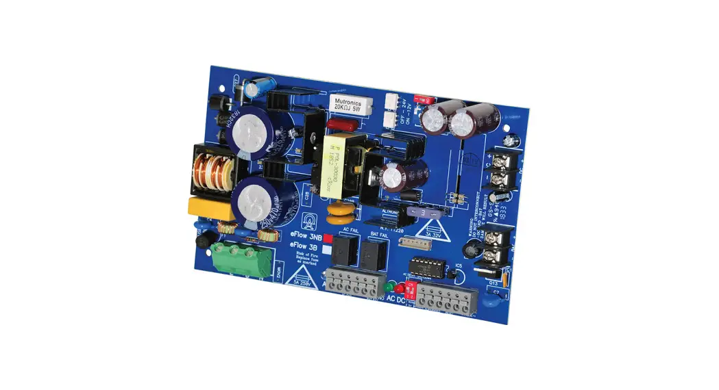
![]() 3NBV eFlow NBV Series Power Supply or Charger Boards
3NBV eFlow NBV Series Power Supply or Charger Boards
Instruction Manual
eFlow3NBV eFlow NBV Series Power Supply or Charger Boards
Models Include:
| eFlow3NBV – 12 or 24VDC @ 2A | eFlow102NBV – 12VDC @ 10A |
| eFlow4NBV – 12 or 24VDC @ 4A | eFlow104NBV – 24VDC @ 10A |
| eFlow6NBV – 12 or 24VDC @ 6A | |
Overview:
Altronix flew power supply/chargers convert a 220VAC (working range 198VAC – 256VAC), 50/60Hz input to a 12VDC or 24VDC output.
Specifications:
| Altronix Model Nuber | Input Rating 220VAC 50/60Hz | Output Voltage (Current) | Aux. Output (unswitched) | Maximum Charge Current | |
| 12VDC | 24VDC | ||||
| eFlow3NBV | 2.1A | 2A | 2A | 1A | 1.54A |
| eFlow4NBV | 2.1A | 4A | 4A | 1A | 1.54A |
| eFlow6NBV | 2.1A | 6A | 6A | 1A | 1.54A |
| eFlow102NBV | 2.1A | 10A | – | 1A | 1.54A |
| eFlow104NBV | 2.7A | – | 10A | 1A | 1.54A |
All of the above Power Supply/Chargers can be installed in Trove1 and Trove2 Access and Power Integration Systems and Maximal Series.
Features:
Agency Listings:
- CE European Conformity.
Output:
- Overvoltage protection .
- Filtered and electronically regulated outputs.
Battery Backup:
- Built-in charger for sealed lead acid or gel-type batteries.
- Automatic switch over to stand-by battery when AC fails.
- Transfer to stand-by battery power is instantaneous with no interruption.
Fire Alarm Disconnect:
- Supervised Fire Alarm disconnect (latching or non-latching) 10K EOL resistor. Operates on a normally open (NO) or normally closed (NC) trigger.
Supervision:
- AC fails supervision (form “C” contacts).
- Battery fail and presence supervision (form “C” contacts).
- Low power shutdown. Shuts down DC output terminals if battery voltage drops below 80% of nominal. Prevents deep battery discharge.
Visual Indicators:
- Green AC Power LED indicates 220VAC present.
- AC input and DC output LED indicators.
Additional Features:
- Short circuit and overload protection.
Board Dimensions (approximate L x W x H):
eFlow3NBV, eFlow4NBV,
eFlow6NBV, eFlow102NBV:
7 .5” x 4 .6” x 1 .75”
(190 .5mm x 116 .8mm x 44 .5mm)
eFlow104NBV:
8 .25” x 4 .56” x 1 .5”
(209 .5mm x 115 .8mm x 38 .1mm) .
Stand-by Specifications:
eFlow3NBV:
| Battery | Burg. Applications 4 hr. Stand-by/15 min. Alarm | Fire Applications 24 hr. Stand-by/5 min. Alarm | Access Control ApplicationsStand-by |
| 7AH | 0.4A/2A | – | 1.5 Hours/2A |
| 12AH | 1A/2A | 0.3A/2A | 3.5 Hours/2A |
| 40AH | 2A/2A | 1.2A/2A | Over 4 Hours/2A |
| 65AH | 2A/2A | 1.5A/2A | Over 4 Hours/2A |
eFlow4NBV:
| Battery | Burg. Applications 4 hr. Stand-by/15 min. Alarm | Fire Applications 24 hr. Stand-by/5 min. Alarm | Access Control Applications Stand-by |
| 7AH | 0.4A/4A | – | 15 Mins./4A |
| 12AH | 1A/4A | 0.3A/4A | 35 Mins./4A |
| 40AH | 4A/4A | 1.2A/4A | Over 4 Hours/4A |
| 65AH | 4A/4A | 1.5A/4A | Over 4 Hours/4A |
eFlow6NBV:
| Battery | Burg. Applications 4 hr. Stand-by/15 min. Alarm | Fire Applications 24 hr. Stand-by/5 min. Alarm | Access Control Applications Stand-by |
| 7AH | 0.4A/6A | – | 10 Mins./6A |
| 12AH | 1A/6A | 0.3A/6A | 35 Mins./6A |
| 40AH | 6A/6A | 1.2A/6A | Over 4 Hours/6A |
| 65AH | 6A/6A | 1.5A/6A | Over 4 Hours/6A |
eFlow102NBV:
| Battery | Burg. Applications 4 hr. Stand-by/15 min. Alarm | Fire Applications 24 hr. Stand-by/5 min. Alarm | Access Control Applications Stand-by |
| 7AH | 0.4A/10A | N/A | 5 Mins./10A |
| 12AH | 1A/10A | 0.3A/10A | 15 Mins./10A |
| 40AH | 6A/10A | 1.2A/10A | Over 2 Hours/10A |
| 65AH | 6A/10A | 1.5A/10A | Over 4 Hours/10A |
eFlow104NBV:
| Battery | Burg. Applications 4 hr. Stand-by/15 min. Alarm | Fire Applications 24 hr. Stand-by/5 min. Alarm | Access Control Applications Stand-by |
| 7AH | 0.4A/10A | N/A | 5 Mins./10A |
| 12AH | 1A/10A | 0.3A/10A | 15 Mins./10A |
| 40AH | 6A/10A | 1.2A/10A | Over 2 Hours/10A |
| 65AH | 6A/10A | 1.5A/10A | Over 4 Hours/10A |
Installation Instructions:
Wiring methods shall be in accordance with the National Electrical Code/NFPA 70/NFPA 72/ANSI, the Canadian
Electrical Code and with all local codes and authorities having jurisdiction. The product is intended for indoor use only.
- Mount the eFlowNBV power supply/charger in desired location/enclosure (mounting hardware included).
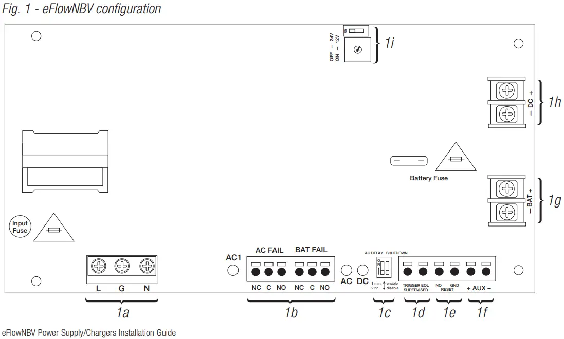
Use metal standoffs for the bottom mounting holes to provide sufficient grounding for the board. - Set desired DC output voltage by setting SW1 to the appropriate position on the power supply board (Fig. 1i, pg. 5).
- Connect unswitched AC power (220VAC, 50/60Hz) to terminals marked [L, G, N] (Fig. 1a, pg. 5).
Use 14 AWG or larger for all power connections. Secure green wire leads to earth ground.
Keep power-limited wiring separate from non-power-limited wiring (220VAC, 50/60Hz Input,
DC Output (refer to Specifications chart pg. 3), Battery Wires).
Minimum 0.25” spacing must be provided.
CAUTION: Do not touch exposed metal parts.
Shut branch circuit power before installing or servicing equipment.
There are no user-serviceable parts inside.
Refer installation and servicing to qualified service personnel. - Measure output voltage before connecting devices. This helps avoid potential damage.
- Connect devices to be powered to terminals marked [– DC +] (Fig. 1h, pg. 5).
For auxiliary device connection, this output will not be affected by Low Power Disconnect or Fire Alarm Interface. Connect the device to terminals marked [+ AUX –] (Fig. 1f, pg. 5). - For Access Control applications batteries are optional. When batteries are not used, a loss of AC will result in the loss of output voltage. When the use of stand-by batteries is desired, they must be lead acid or gel type.
Connect the battery to terminals marked [– BAT +] (Fig. 1g, pg. 5) . Use two (2) 12VDC batteries connected in series for 24VDC operation (battery leads included). Use batteries – Castle CL1270 (12V/7AH), CL12120 (12V/12AH), CL12400 (12V/40AH), CL12650 (12V/65AH) batteries or UL-recognized BAZR2 batteries of an appropriate rating.
Note: Separate enclosures must be used for housing 40AH or 65AH batteries. - Connect appropriate signaling notification devices to AC FAIL & BAT FAIL (Fig. 1b, pg. 5) supervisory relay outputs.
- To delay AC reporting for 2 hrs ., set SW2 to the appropriate DIP switch position [AC Delay] (Fig. 1c, pg. 5).
- To enable or disable Low Output Power Shutdown set SW2 to the appropriate DIP switch position [Shutdown](Fig. 1c, pg. 5) .
10 . A short or NO or NC input triggers FACP [Trigger EOL Shutdown] (Fig. 1d, pg. 5).
11 . Place a jumper for non-latching FACP. A momentary short on these terminals resets FACP latching
[Trigger EOL Shutdown] (Fig. 1e, pg. 5).
Wiring:
Use 18 AWG or larger for all low voltage power connections.
Note: Take care to keep power-limited circuits separate from non-power-limited wiring (220VAC, Battery)
Maintenance:
The unit should be tested at least once a year for the proper operation as follows:
Output Voltage Test: Under normal load conditions, the DC output voltage should be checked for proper voltage level.
Battery Test:
Under normal load, conditions check that the battery is fully charged, and check the specified voltage (12VDC @ 13 .2 or 24VDC @ 26 .4) both at the battery terminal and at the board terminals marked [– BAT +] to ensure that there is no break in the battery connection wires.
Replacing Batteries: Disconnect existing batteries. Connect the battery to the terminals marked [– BAT +]. Use two (2) 12VDC batteries connected in series for 24VDC operation.
LED Diagnostics:
| Red (DC) | Clear (AC1) / Green (AC) | Power Supply Status |
| ON | ON | Normal operating condition. |
| ON | OFF | Loss of AC. The standby battery is supplying power. |
| OFF | ON | No DC output. |
| OFF | OFF | Loss of AC. Discharged or no stand-by battery. No DC output. |
Terminal Identification:
| Terminal Legend | Function/Description |
| L, G, N | Connect 220VAC, 50/60Hz to these terminals: L to hot, N to neutral, G to the ground (Fig. 1a, pg. 5). |
| – DC + (Fig. 1h, pg. 5) | eFlow3NBV: 12VDC or 24VDC @ 2A continuous output (power-limited output). eFlow4NBV: 12VDC or 24VDC @ 4A continuous output (power-limited output). eFlow6NBV: 12VDC or 24VDC @ 6A continuous output (non power-limited output). eFlow102NBV: 12VDC @ 10A continuous output (non power-limited output). eFlow104NBV: 24VDC @ 10A continuous output (non power-limited output). |
| Trigger EOL Supervised | Fire Alarm Interface trigger input from a short or FACP. Trigger inputs can be normally open and normally closed from an FACP output circuit (power-limited input) (Fig. 1d, pg. 5). |
| NO, GND RESET | FACP interface latching or non-latching (power-limited output) (Fig. 1c, pg. 5). |
| + AUX – | Auxiliary Power-Limited output rated @ 1A (unswitched) (power-limited output) (Fig. 1f, pg. 5). |
| AC Fail NC, C, NO | Indicates loss of AC power, e.g. connect to audible device or alarm panel. The relay is normally energized when AC power is present. Contact rating 1A @ 30VDC (power-limited) (Fig. 1b, pg. 5). |
| Bat Fail NC, C, NO | Indicates low battery condition, e.g. connect to the alarm panel. The relay is normally energized when DC power is present. Contact rating 1A @ 30VDC. A removed battery is reported within 5 minutes. Battery reconnection is reported within 1 minute (power-limited) (Fig. 1b, pg. 5). |
| – BAT + | Stand-by battery connections. Maximum charge current 1.54A (non-power-limited) (Fig. 1g, pg. 5). |
Notes:
![]() eFlow Power Supply/Chargers can be Controlled and Monitored while Reporting
eFlow Power Supply/Chargers can be Controlled and Monitored while Reporting
Power/Diagnostics from Anywhere over the Network…
![]()
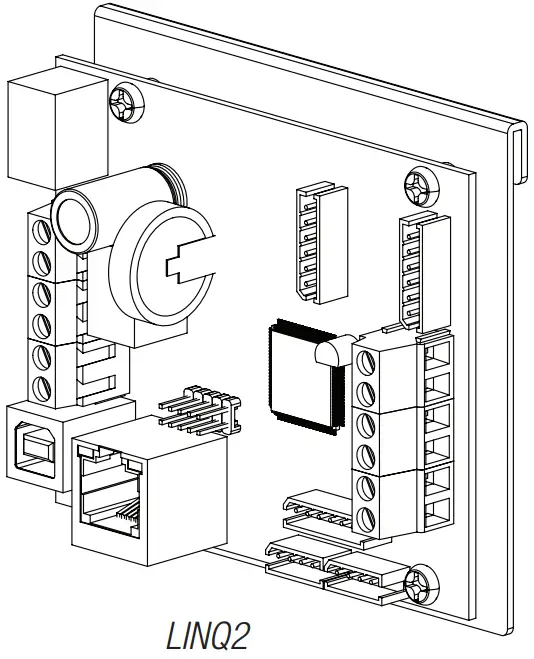
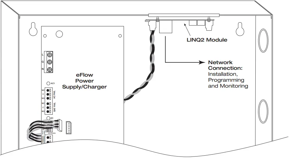
LINQ2 – Network Communication Module
LINQ2 provides remote IP access to real-time data from eFlow power supply/chargers to help keep systems up and running at optimal levels. It facilitates fast and easy installation and set-up, minimizes system downtime, and eliminates unnecessary service calls, which helps reduce Total Cost of Ownership (TCO) – as well as creates a new source of Recurring Monthly Revenue (RMR).
Features:
- UL is Listed in the U .S . and Canada.
- Local or remote control of up to (2) two Altronix eFlow power output(s) via LAN and/or WAN.
- Monitor real-time diagnostics: DC output voltage, output current, AC & battery status/service, input trigger state change, output state change, and unit temperature.
- Access control and user management: Restrict read/write, Restrict users to specific resources
- Two (2) integral network controlled Form “C” Relays.
- Three (3) programmable input triggers: Control relays and power supplies via external hardware sources.
- Email and Windows Dashboard notifications
- The event log tracks history.
- Secure Socket Layer (SSL).
- Programmable via USB or web browser – includes operating software and 6 ft. USB cable.
LINQ2 Mounts Inside any eFlow Enclosure
![]()
Altronix is not responsible for any typographical errors.
140 58th Street, Brooklyn, New York 11220 USA
phone: 718-567-8181
fax: 718-567-9056
website: www.altronix.com
e-mail: [email protected]
Lifetime Warranty
IIeFlowNBV
F23U
eFlowNBV Power Supply/Chargers Installation Guide


