![]()
Alliance_eROU & eROUa
User Manual
Document Reference:
| Version: | V1.1 |
| Document Status: | Release 2 |
| Issue Date: | 23-Jun-20 |
| Author: | Yang-Su Kim |
| Department: | R&D Division Team 2 |
| Authorizing Manager: | hyun-suk Chae |
REVISION HISTORY
| Version | Issue Date | No. of Pages | Initials | Details of Revision Changes |
| V 1.0 | 09-Mar-20 | Original | ||
| V 1.1 | Jun 23,2020 | eROUa_682335 Add | ||
Technical Support
SOLiD serial numbers must be available to authorize technical support and/or to establish a return authorization for defective units. The serial numbers are located on the back of the unit, as well as on the box in which they were delivered. Additional support information may be obtained by accessing the SOLiD Tehcnology, Inc. website at www.solid.co.kr or send email at [email protected]
This manual is produced by Global Business Division Business Team Printed in Korea.
Section1
Safety & Certification Notice
“Only qualified personnel should handle the DAS equipment. Any person involved in installation or service of the DAS should understand and follow these safety guidelines.”
- Obey all general and regional installation and safety regulations relating to work on high voltage installations, as well as regulations covering correct use of tools and personal protective equipment.
- The power supply unit in repeaters contains dangerous voltage level, which can cause electric shock. Switch the mains off prior to any work in such a repeater. Any local regulations are to be followed when servicing repeaters.
- eROU equipment is exclusive to the indoor.
- Use this unit only for the purpose specified by the manufacturer. Do not carry out any modifications or fit any spare parts which are not sold or recommended by the manufacturer. This could cause fires, electric shock or other injuries.
- Any DAS system or Fiber BDA will generate radio (RF) signals and continuously emit RF energy. Avoid prolonged exposure to the antennas. SOLiD recommends maintaining a 120 cm minimum clearance from the antenna while the system is operating.
- Do not operate this unit on or close to flammable materials, as the unit may reach high temperatures due to power dissipation.
- Do not use any solvents, chemicals, or cleaning solutions containing alcohol, ammonia, or abrasives on the DAS equipment. Alcohol may be used to clean fiber optic cabling ends and connectors.
- To prevent electrical shock, switch the main power supply off prior to working with the DAS System or Fiber BDA. Never install or use electrical equipment in a wet location or during a lightning storm.
- Do not look into the ends of any optical fiber or directly into the optical transceiver of any digital unit. Use an optical spectrum analyzer to verify active fibers. Place a protective cap over any radiating transceiver or optical fiber connector to avoid the potential of radiation exposure.
- Allow sufficient fiber length to permit routing without severe bends.
- For pluggable equipment, make sure to install the socket outlet near the equipment so that it is easily accessible.
- A readily accessible disconnect device shall be incorporated external to the equipment.
- This power of this system shall be supplied through wiring installed in a normal building.
- The specialized installer shall guide the installation of the product within the authorization, and the specialized installer shall properly set up the CBRS band to satisfy EIRP<23dBm / 10MHz depending on the installation condition.
If powered directly from the mains distribution system, it shall be used additional protection, such as overvoltage protection device
- Only 50 ohm rated antennas, cables and passive equipment shall be used with this remote. Any equipment attached to this device not meeting this standard may cause degradation and unwanted signals in the bi-directional system. All components connected to this device must operate in the frequency range of this device.
- Only 50 ohm rated antennas, cables and passive components operating from 150 – 3 GHz shall be used with this device.
- The head end unit must always be connected to the Base Station using a direct cabled connection. This system has not been approved for use with a wireless connection via server antenna to the base station.
- Access can only be gained by SERVICE PERSONS or by USERS who have been instructed about the reasons for the restrictions applied to the location and about any precautions that shall be taken; and
- Access is through the use of a TOOL or lock and key, or other means of security, and is on trolled by the authority responsible for the location.
- Notice! Be careful not to touch the Heat-sink part due to high temperature.

- Signal booster warning label message should include
WARNING. This is NOT a CONSUMER device. It is designed for installation by FCC LICENSEES and QUALIFIED INSTALLERS. You MUST have an FCC LICENSE or express consent of an FCC Licensee to operate this device. Unauthorized use may result in significant forfeiture penalties, including penalties in excess of $100,000 for each continuing violation. - IC Booster warning label message should include
WARNING: This is NOT a CONSUMER device. It is designed for installation by an installer approved by an ISED licensee. You MUST have an ISED LICENCE or the express consent of an ISED licensee to operate this device
- Certification
• FCC: This equipment complies with the applicable sections of Title 47 CFR Parts 15,22,24,27 and 90- Use of unauthorized antennas, cables, and/or coupling devices not conforming with ERP/EIRP and/or indoor-only restrictions is prohibited.
- Home/ personal use are prohibited.
- UL/CUL: This equipment complies with UL and CUL 62368-1 Standard for safety for information technology equipment, including electrical business equipment
- FDA/CDRH: This equipment uses a Class 1 LASER according to FDA/CDRH Rules. This product conforms to all applicable standards of 21 CFR Chapter 1, Subchaper J, Part 1040
FCC Part 15.105 statement
This equipment has been tested and found to comply with the limits for a Class A digital device, pursuant to part 15 of the FCC Rules. These limits are designed to provide reasonable protection against harmful interference when the equipment is operated in a commercial environment. This equipment generates, uses, and can radiate radio frequency energy and, if not installed and used in accordance with the instruction manual, may cause harmful interference to radio communications. Operation of this equipment in a residential area is likely to cause harmful interference in which case the user will be required to correct the interference at his own expense.
FCC Part 15.21 statement
Any changes or modifications not expressly approved by the party responsible for compliance could void the user’s authority to operate this equipment.
RF Exposure Statement The antenna(s) must be installed such that a minimum separation distance of at least 120 cm is maintained between the radiator (antenna) and all persons at all times. This device must not be co-located or operating in conjunction with any other antenna or transmitter.
RSS-GEN, Sec. 7.1.2 (transmitters)
Under Industry Canada regulations, this radio transmitter may only operate using an antenna of a type and maximum (or lesser) gain approved for the transmitter by Industry Canada. To reduce potential radio interference to other users, the antenna type and its gain should be so chosen that the equivalent isotropically radiated power (e.i.r.p.) is not more than that necessary for successful communication.
RSS-GEN, Sec. 7.1.2 (detachable antennas)
This radio transmitter (identify the device by certification number, or model number if Category II)has been approved by Industry Canada to operate with the antenna types listed below with the maximum permissible gain and required antenna impedance for each antenna type indicated. Antenna types not included in this list, having a gain greater than the maximum gain indicated for that type, are strictly prohibited for use with this device. (Antenna Max. Gain: 17dBi)
RF Radiation Exposure
This equipment complies with RF radiation exposure limits set forth for an uncontrolled environment. This equipment should be installed and operated with a minimum distance of 120 cm between the radiator and your body. This transmitter must not be co-located or operating in conjunction with any other antenna or transmitter. RF exposure will be addressed at time of installation and the use of higher gain antennas may require larger separation distances.
Section2
System configuration and Functions
eROU (edge Remote Optic Unit) & eROUa
eROU receives TX optical signals from eHUB and converts them into RF signals. The converted RF signal is radiated to the antenna port via the AMP and Multiplexer. When receiving RX signals through the antenna port, this unit filters out-of-band signals in a corresponding Multiplexer and sends the results to OPTIC to make electronic-optical conversion of them. After converted, the signals are sent to a upper device of eHUB.
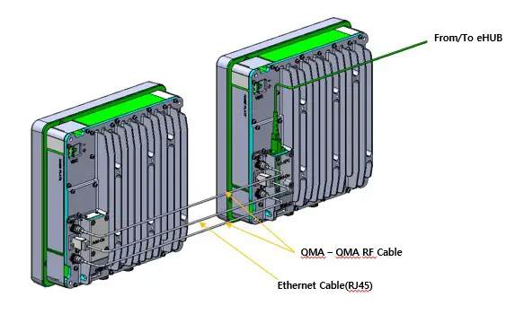
For this application, eROUa receives RF signals from eROU. The received RF signals are radiated through the AMP and multiplexer to the antenna ports. When the device receives an RX signal through the antenna port, it filters out-of-band signals from the appropriate multiplexer and transmits the results to the RF signal. The signal is transmitted to the upper unit of the eHUB.
In addition, if band extension is required, another eROU can be added up to three using optical splitters and RF ports. However, the band expansion equipment will be developed in the future. And eROU is divided into an Internal product with an antenna and an External product without an antenna.
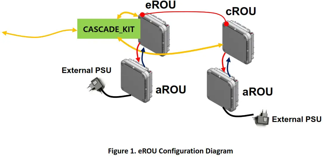
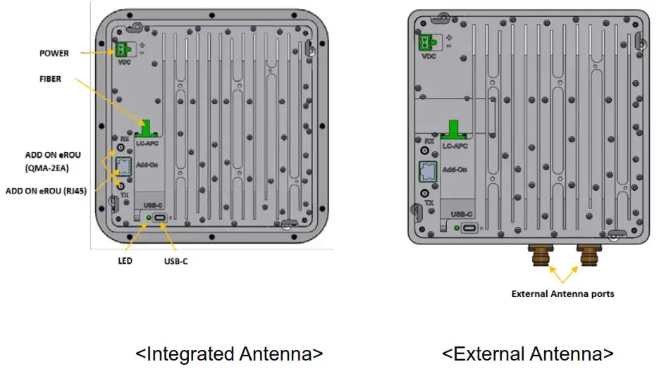
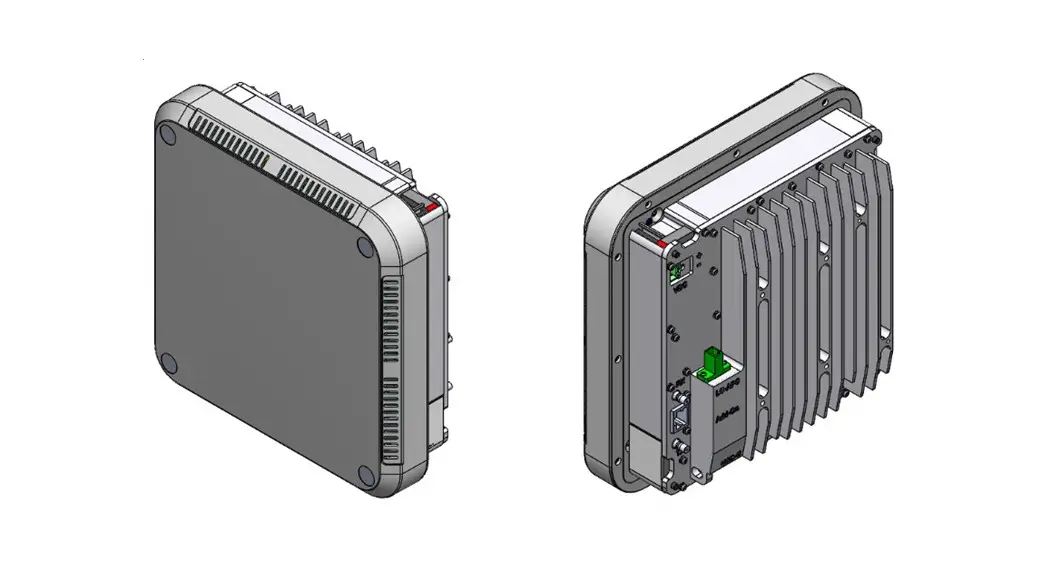
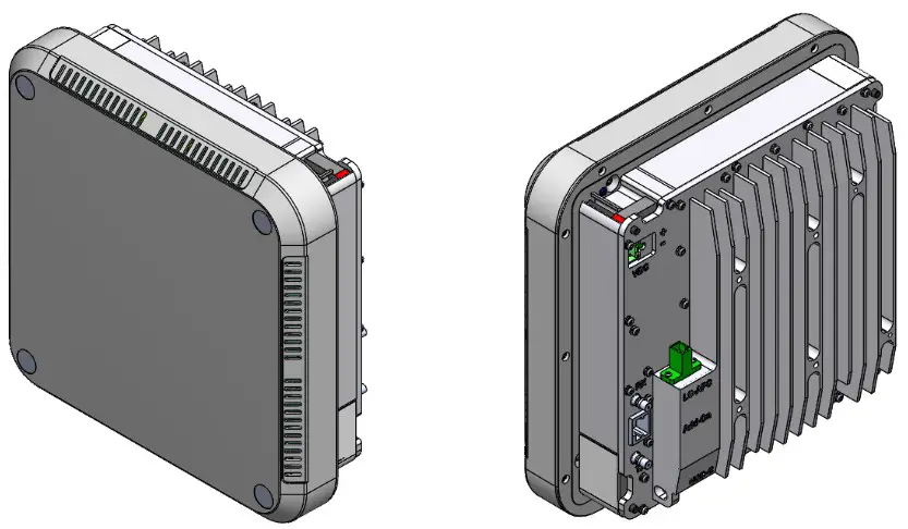
Figure 2. eROU outer Look
<External Antenna>
Figure 3. eROUa outer Look
Specifications of eROUa
| Item | Spec. | Remark | ||
| eROU | ||||
| The rated mean output Power per band | 600 700LTE_FN 8085 | +19dBm (Tolerance: ±1dB) | ||
| 1900P AWS13 2300WCS 2500_100TDD | +23dBm (Tolerance: ±1dB) | |||
| The nominal downlink bandwidth | 600 | 35MHz | ||
| 700LTE_FN | 39MHz | |||
| 8085 | 32MHz | |||
| 1900P | 65MHz | |||
| AWS13 | 70MHz | |||
| 2300WCS | 10MHz | |||
| 2500_100TDD | 19:1MHz | |||
| The nominal uplink bandwidth | 600 | 35MHz | ||
| 700LTE_FN | 7011FN 81 : 17MHz 703FN 82 : 21MHz | |||
| 8085 | 32MHz | |||
| 1900P | 65MHz | |||
| AWS13 | 70MHz | |||
| 2300WCS | 10MHz | |||
| 2500_100TDD | 194MHz | |||
| The nominal passband gain | Downlink | 600 | 61dB | |
| 7COLTE_FN | 63dB | |||
| 8085 | S8dB | |||
| 1900P | 67dB | |||
| AW513 | 67dB | |||
| 2300WCS | 67dB | |||
| 2500_100TDD | 67dB | |||
| Uplink | 600 8085 | 52dB | ||
| 2300WCS | 48dB | |||
| 700LTE_FN 1900P AWS13 2500_100TDD | 45dB | |||
| Input/ Output Impedance | 50 ohm | |||
| Weight | 2.6 kg(Internal) | Common Part | ||
| 3.0 kg(External) | ||||
| Power consumption | 35W | |||
| Temperature range | -5°C to +50°C | Ambient Temperature | ||
| Humidity Range | 5% — 90% | Non-condensing | ||
| Sealing (Remote Unit) | IEC/UL/CSA 62368-1 | |||
| Size(mm) | 220 x 220 x 90 | Integrated Antenna | ||
| 200 x 200 x 73 | External Antenna | |||
Port on eROU & eROUa
Functions
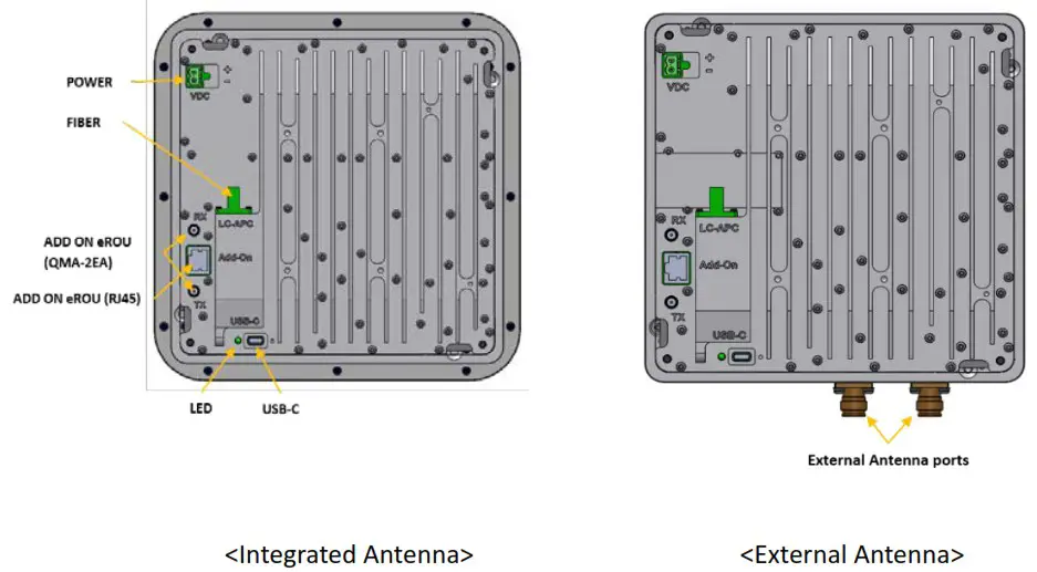
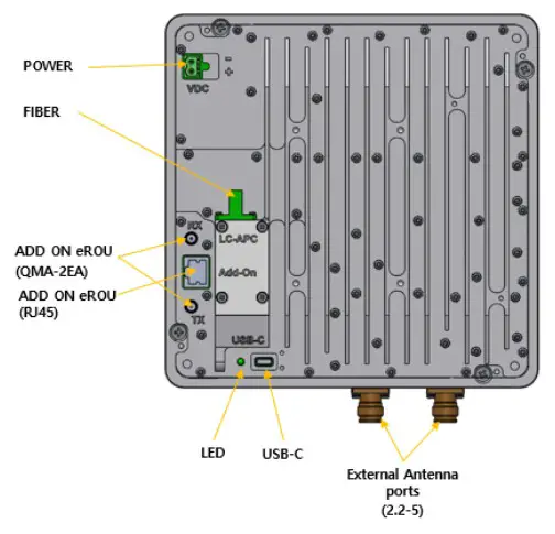
Figure 4. The name of each port on eROU
<External Antenna>
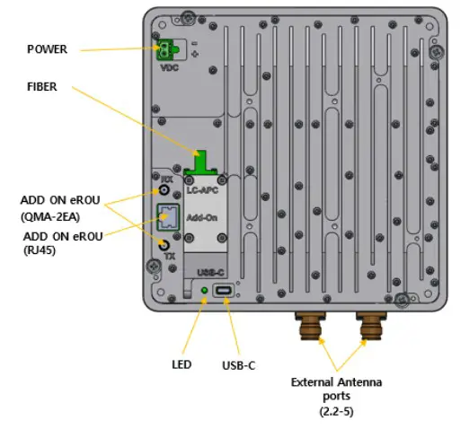
Figure 5. The name of each port on eROUa
| No | Port | Quantity | Remark |
| 1 | Optical Port | lEA | LC/APC |
| 2 | ANTENNA PORT(External Only) | lEA | 2.2-5 type female |
| 3 | Power IN | lEA | Terminal_Block_CONN_2P(TLPS-302V-02P-G) |
| 4 | ADD ON eROU Port | 2EA | QMA-type female |
| 5 | ADD ON eROU Port | lEA | 11145 |
| 6 | USB Port | lEA | USB-C Type |
AC/DC Adaptor information
| Manufacturer | SHENZHEN HONOR ELECTRONIC |
| Model name | ADS-65DI-48-1 48065E |
| Specification | Input range 100-240V, 50/60Hz Output range 48Vdc 1.35A / 64.8W |
This product is intended to be supplied by a Listed Switching Adapter marked “Class 2” or “LPS” or “PS2” and rated from 100 – 240V~; 50/60HZ; 1.5A max.
Section3
System Installation
eROU Installation
The following table shows the required accessories and tools for installing eROU.
| No | Tools | Q’ty | Specification | Remark |
| 1 | 1 | (+), Ø3.0 Length is more than 20mm | For fixing |
eROU Enclosure installation
The eROU can be mounted on a wall or ceiling. and divided into the version of External Antena and the version of Internal Antena.
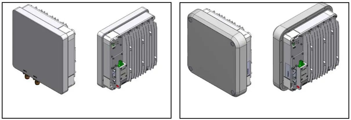
Figure 3. eROU appearance (Left : External Antenna, Right : Internal Antenna)
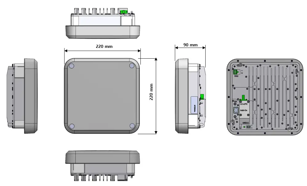
Figure 4. Dimension used to install eROU (internal)
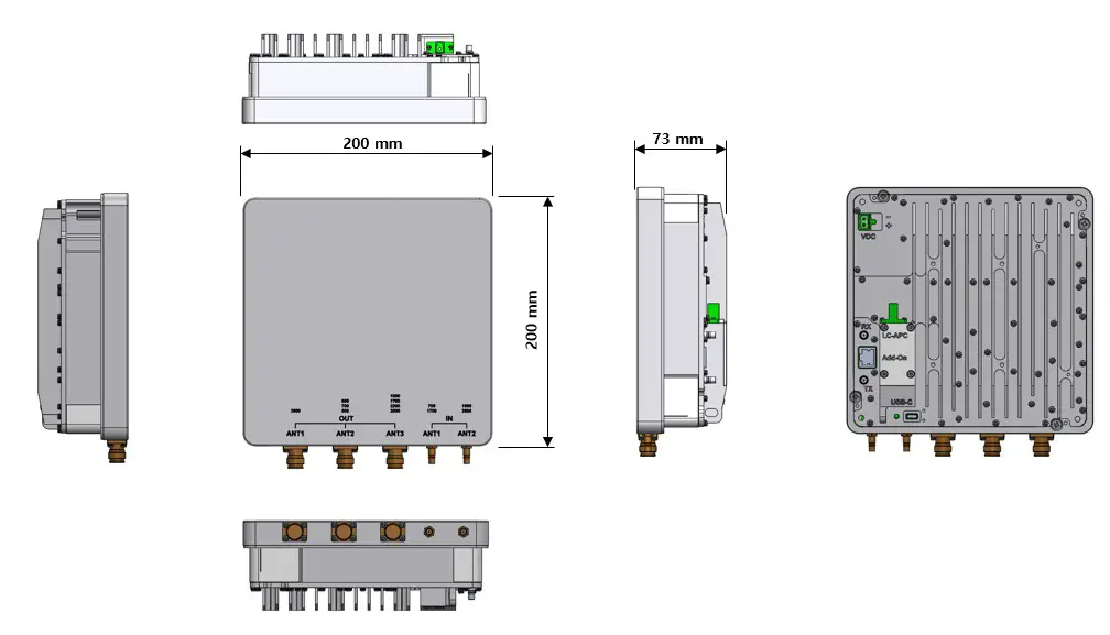
Figure 3. Dimension used to install eROU (external)
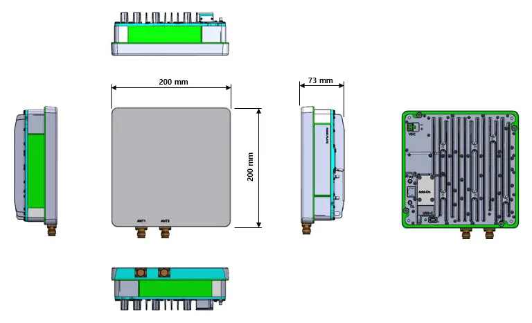
Figure 4. Dimension used to install eROUa (external)
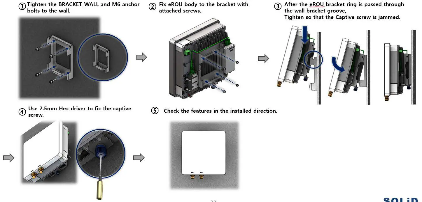
eROU(External Antenna) Mount Installation
Installation Cable Gland
eROU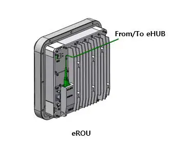
Combine of eROU and cROU
Power cabling
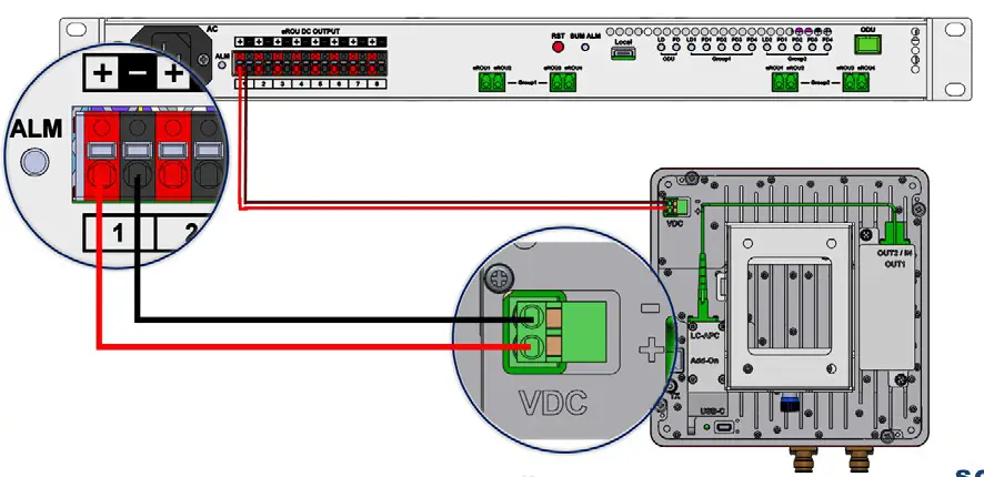
- The eROU receives DC power from the eHub or external adapter.
- Cable length between eHub and even supports up to 1 km.(Cable specifications recommend AWG14 and Cable type shall be marked “CL2”.)
- If the maximum length between the eHub and the eROU is exceeded, the use of the External Adapter is recommended.
** Adaptor is extra purchases. Specified below shall be used only adapter.
Confidential & Proprietary


