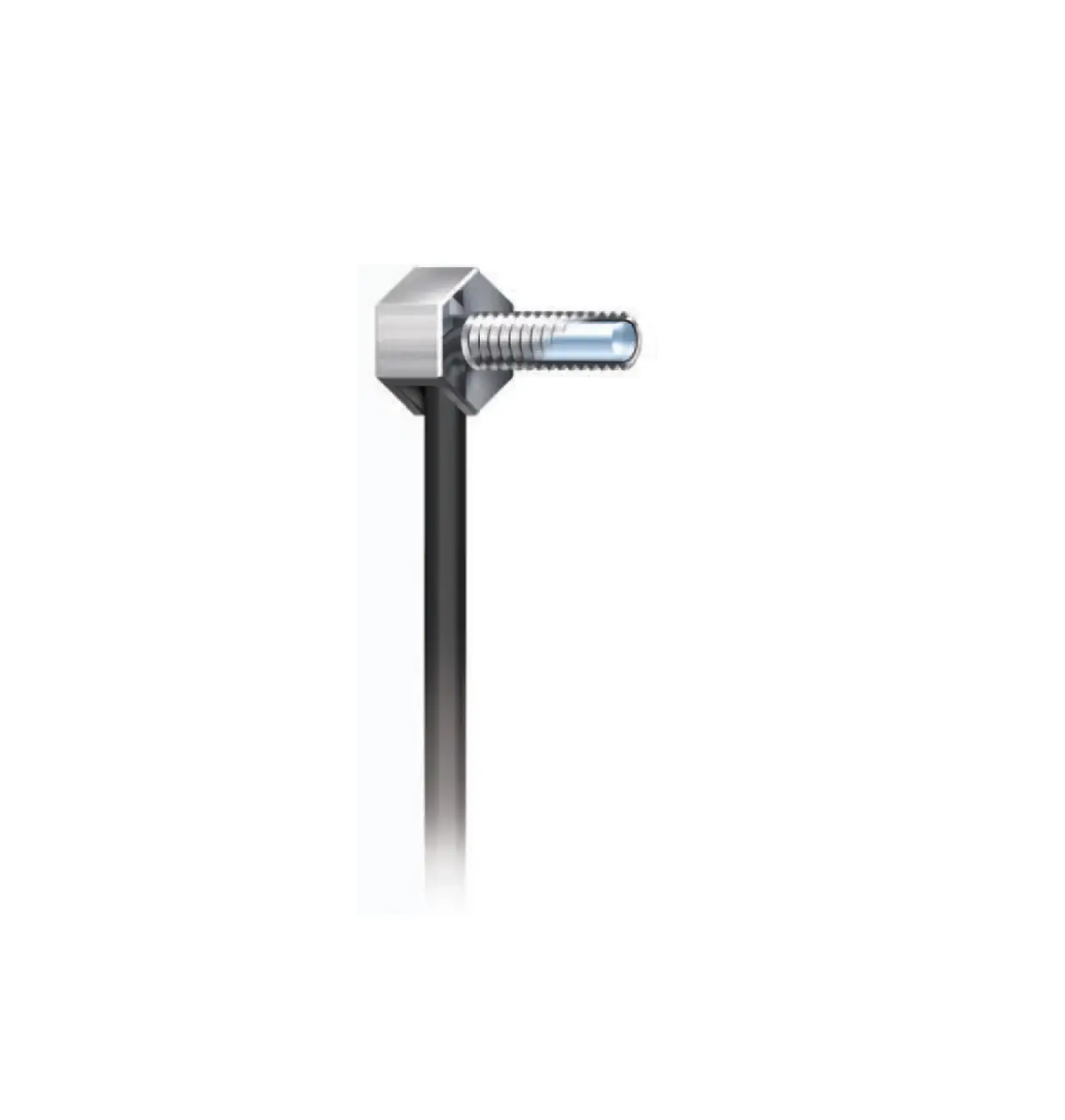
OMRON E32-LT11N Hex Shaped Fiber Unit
NEW STANDARD FOR THE FUTURE
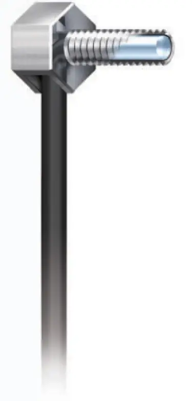
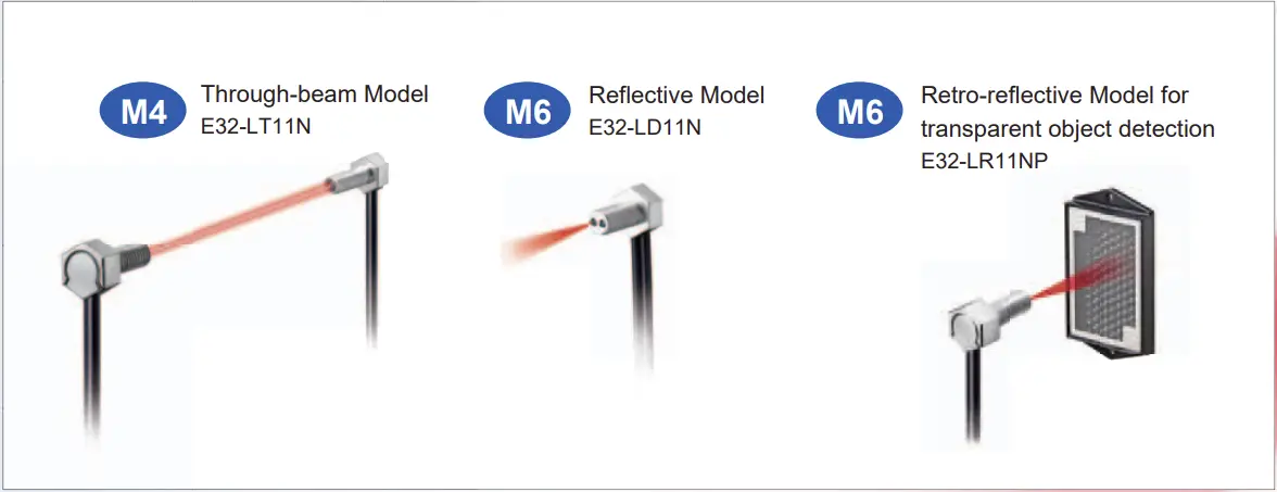
Introducing Hex-shaped Models with Build-in Lenses
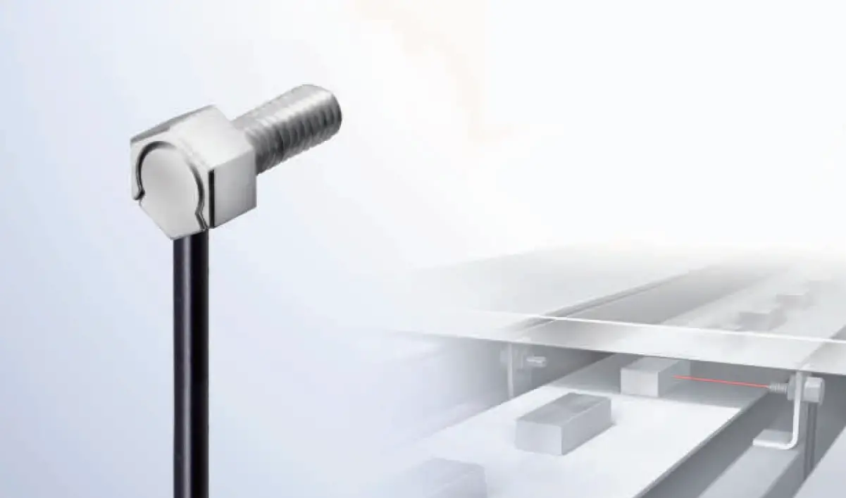
Hex-shaped Fiber ![]() Unit Series
Unit Series
Fiber Units with Build-in Lenses
provide more stable detection and simpler, more reliable installation.
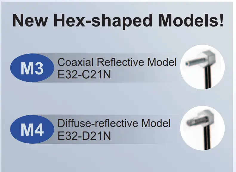
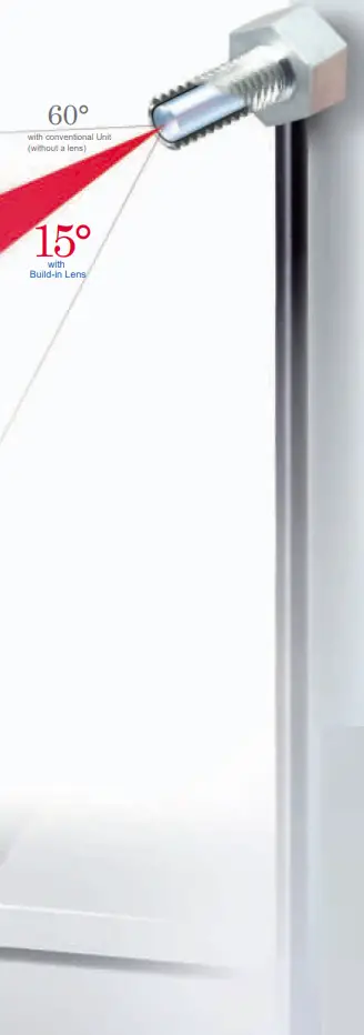
Hex-shaped models are now available with high-power built-in lenses for stable detection.
Achieve stable detection and easy onsite application.
Hex Shape
Build-in Lens
Stable Detection
Long-term Stable Detection Even in Dusty Environments
The E32-LT11N’s incident light level is approx. 10 times higher than that of the conventional Fiber Units.*1 High power means stable detection even in dusty and dirty environments.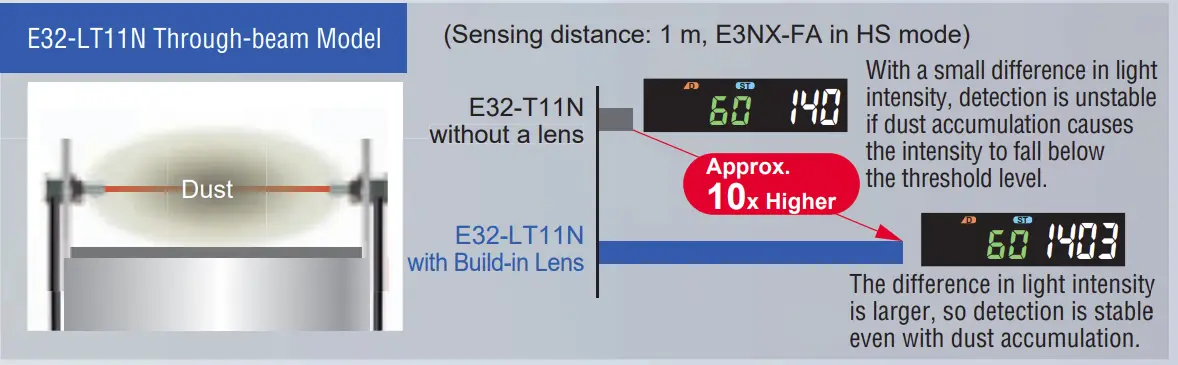
Stable Detection of Target Area Changes
The E32-LD11N’s signal change (S/N ratio) is approx. 3 times higher than that of the conventional Fiber Units.*2 Because the target area is viewed with the narrow field of a 15° aperture angle, there is a greater difference in incident light levels and objects can be detected reliably.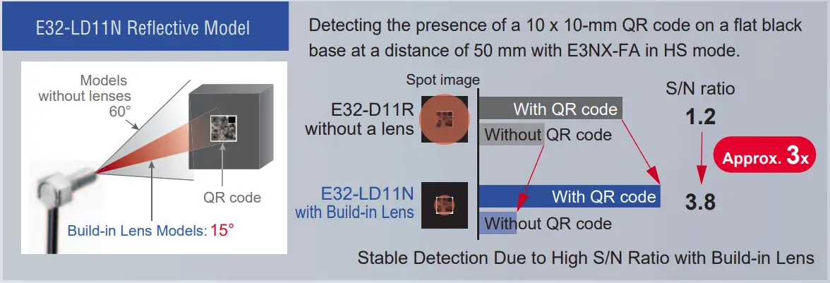
Reduce False Detection Caused by Scattered Light
False Detection is greatly reduced because the 15° aperture angle eliminates scattered light, even in tight spaces.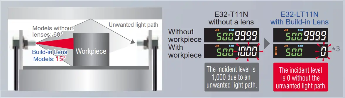
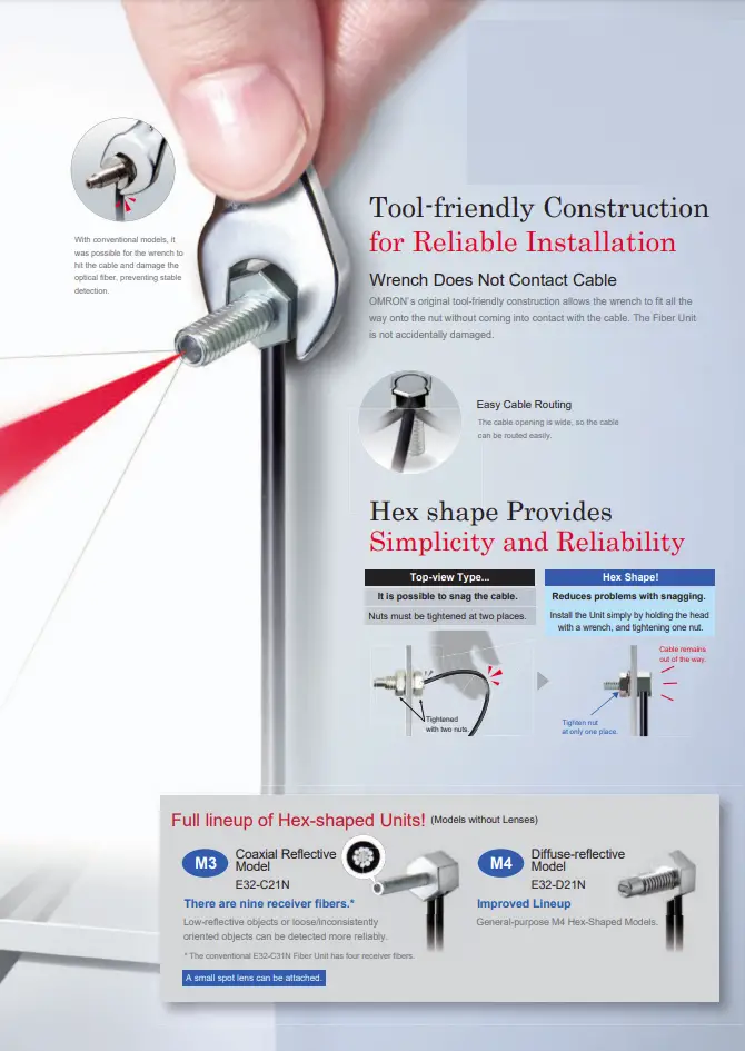
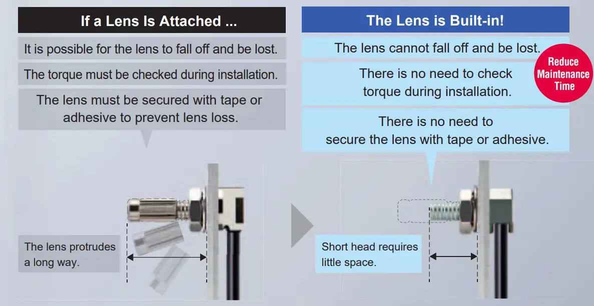
Build-in Lens Provides Simplicity and Reliability
 Through-beam Fiber Units
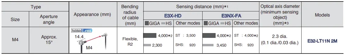
Specifications
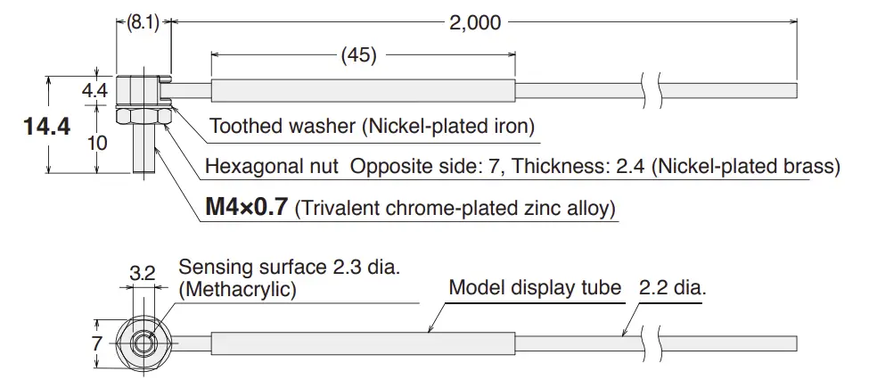
Dimensions (mm) Tolerance class IT16 applies to dimensions in this data sheet unless otherwise specified.
E32-LT11N 2M (Free Cutting)
 Reflective Fiber Units/ Retro-reflective Fiber Units
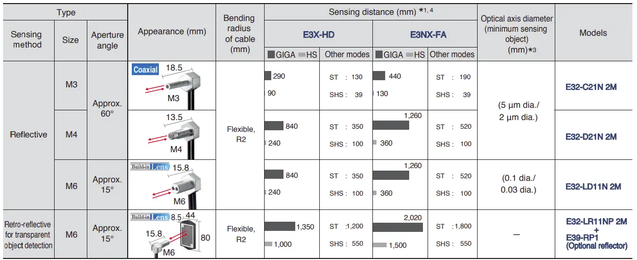
Specification
Dimensions (mm) Tolerance class IT16 applies to dimensions in this data sheet unless otherwise specified.
E32-C21N 2M (Free Cutting)
E32-LD11N 2M (Free Cutting)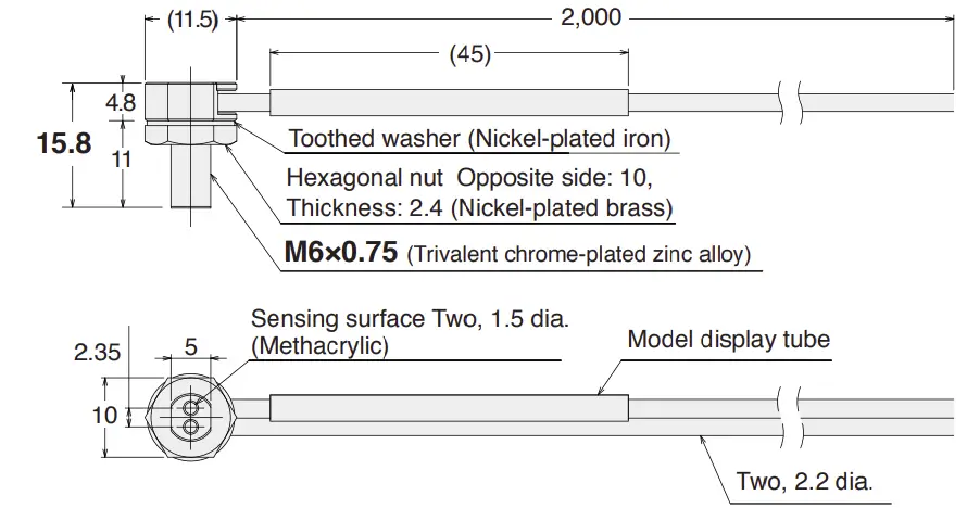
E32-LR11NP 2M (Free Cutting)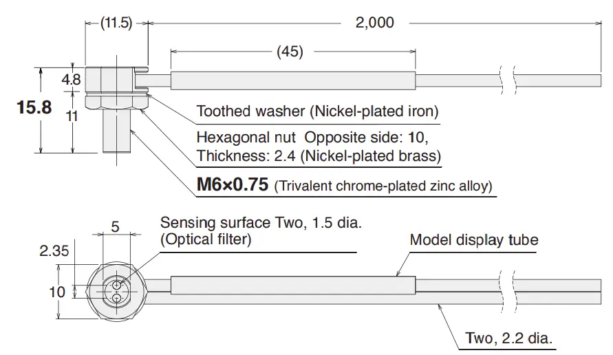
- The following mode names and response times apply to the modes given in the Sensing distance column.
E3X-HD GIGA: Giga-power mode (16 ms), HS: High-speed mode (250 μs), ST: Standard mode (1 ms), and SHS: Super-high-speed mode (NPN output: 50 μs, PNP output: 55 μs)
E3NX-FA GIGA: Giga-power mode (16 ms), HS: High-speed mode (250 μs), ST: Standard mode (1 ms), and SHS: Super-high-speed mode (30 μs) - The optical fiber is 2 m long on each side, so the sensing distance is 4,000 mm.
- The values for the minimum sensing object are reference values that indicate values obtained in standard mode with the sensing distance and sensitivity set to the optimum values.
The first value is for the E3X-HD and the second value is for the E3NX-FA. - The sensing distances for Reflective Fiber Units are for white paper. The sensing distances for the E32-LD11N 2M are for glossy white paper.
Note. Objects with a high reflection factor may cause the Retro-reflective Fiber Sensor to detect reflected light as incident light.
Detection may be unstable depending on the type of transparent object. Check suitability beforehand.
Installation Information
Through-beam Fiber Units
| Models | Installation | Cable | Weight (packed state) (g) | |||||||
| Ambient temperature | Tightening torque | Mounting hole | Bending radius | Unbendable length | Tensile strength | Sheath material | Core material | Emitter/receiver differentiation | ||
| E32-LT11N 2M | -40 to 70℃ | 0.78 N . m | 4.2 +0.5 dia. 0 | R2 | 0 | 29.4 N | Polyethylene | Plastic | None | Approx. 40 g |
Reflective Fiber Units/ Retro-reflective Fiber Units
| Models | Installation | Cable | Weight (packed state) (g) | |||||||
| Ambient temperature | Tightening torque | Mounting hole | Bending radius | Unbendable length | Tensile strength | Sheath material | Core material | Emitter/receiver differentiation | ||
| E32-C21N 2M | -40 to 70℃ | 0.29 N . m | 3.2 +0.5 dia. 0 |
R2 | 0 | 9.8 N | Polyethylene | Plastic | White line on emitter cable | Approx. 30 g |
| E32-D21N 2M | -40 to 70℃ | 0.78 N . m | 4.2 +0.5 dia. 0 | 0 | 9.8 N | Polyethylene | Plastic | None | Approx. 30 g | |
| E32-LD11N 2M | -40 to 70℃ | 0.98 N . m | 6.2 +0.5 dia. 0 | 0 | 29.4 N | Polyethylene | Plastic | None | Approx. 40 g | |
| E32-LR11NP 2M | -40 to 70℃* | 0.98 N . m | 6.2 +0.5 dia. 0 | 0 | 29.4 N | Polyethylene | Plastic | None | Approx. 40 g | |
* Ambient operating temperature of the recommended reflector (E39-RP1) is -40 to 60℃.
Accessories
| Appearance | Models | Quantity | Remarks |
| E39-F9W13 | 1 | 1.3-dia. Attachment Provided with applicable Fiber Units. Order this accessory separately if you lose or damage it. |
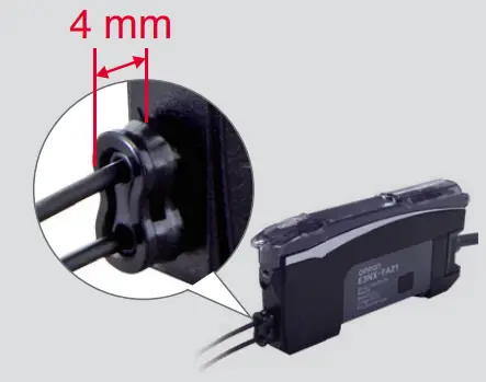 | Improved thin attachment. The protrusion was reduced to help you save space. You can also just insert the cable into this one-piece Attachment to save work. |
Applicable Fiber Units: E32-C21N, E32-D21N
Applicable Fiber Amplifier Units: E3NX-FA, E3X-HD, E3X-DA-S series
Introduction to Fiber Sensors
OMRON also provides many other types of Fiber Sensors.
Refer to Fiber Sensor Best Selection Catalog (E418).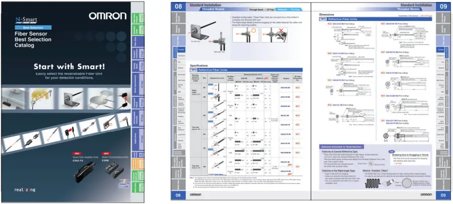
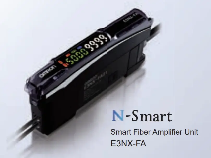
Fiber Amplifier Units
E3X-HD Series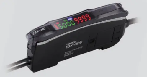 | E3NX-FA Series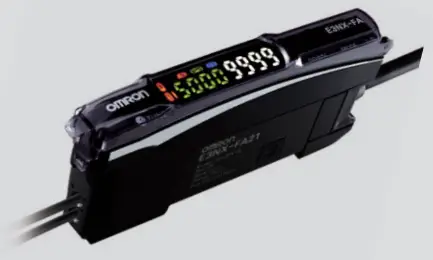 | |||
| Fiber Amplifier Unit specifications | Output | 1 output | 1 or 2 outputs (depending on the model) | |
| External input | Not supported | Supported or not supported (depending on the model) | ||
| Response time* | 50 μs (55 μs)/250 μs/1 ms/16 ms | 30 μs (32 μs)/250 μs/1 ms/16 ms | ||
| (Default: 250 μs) | (Default: 250 μs) | |||
| Sensing distance (Giga-power mode) | E32-LT11N | 4,000 mm | 4,000 mm | |
| E32-LD11N | 840 mm | 1,260 mm | ||
| Minimum sensing object | E32-LT11N | 0.1 mm dia. | 0.03 mm dia. | |
* These are the response times for super-high-speed mode (SHS), high-speed mode (HS), standard mode (Stnd), and GIGA-power mode (GIGA).
The value in parentheses for the super-high-speed mode is for a model with a PNP output.
OMRON Corporation Tokyo, JAPAN
Industrial Automation Company
Contact: www.ia.omron.com
Regional Headquarters
OMRON EUROPE B.V.
Sensor Business Unit
Carl-Benz-Str. 4, D-71154 Nufringen, Germany
Tel: (49) 7032-811-0/Fax: (49) 7032-811-199
OMRON ASIA PACIFIC PTE. LTD.
No. 438A Alexandra Road # 05-05/08 (Lobby 2),
Alexandra Technopark,
Singapore 119967
Tel: (65) 6835-3011/Fax: (65) 6835-2711
OMRON ELECTRONICS LLC
One Commerce Drive Schaumburg,
IL 60173-5302 U.S.A.
Tel: (1) 847-843-7900/Fax: (1) 847-843-7787
OMRON (CHINA) CO., LTD.
Room 2211, Bank of China Tower,
200 Yin Cheng Zhong Road,
PuDong New Area, Shanghai, 200120, China
Tel: (86) 21-5037-2222/Fax: (86) 21-5037-2200

© OMRON Corporation 2013-2021 All Rights Reserved.
In the interest of product improvement,


