BLT: Frequency range:2402∼2480 MHz RF Power:8.91dBm
BT Frequency range:2402∼2480 MHz RF power:9.19dBm wifi frequency range:802.11b/g/n20:2412-2472 MHz 802.11n40:2422-2462 MHz
RF power(dBm): 802.11b:17.15 , 802.11g:15.06 , 802.11n20:14.16, 802.11n40:14.14
 K5
K5
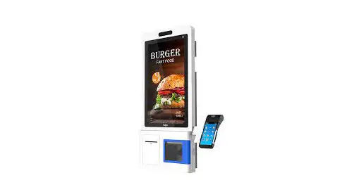
Self-Service Kiosk
User Guide
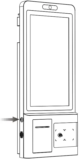
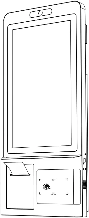
Appearance
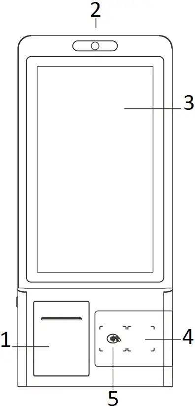
- Printer
- Camera
- Touch Screen
- Barcode Scanner
- NFC
K5 Specification
| Processor | Dual-Core 1.8GHz+ Quad-Core 1.4GHz |
| OS | Android 7.1 |
| Memory | 4GB DDR , 16GB eMMC |
| Display | 21.5-inch LCD Touch Screen , Resolution1080*1920 |
| Thermal Printer | Paper width 80mm , Φ80mm , with auto cutter Printing speed: 150mm/s |
| Camera(Optional) | Single-lens Camera Dual-lens Camera 3D Depth Sensing Camera |
| Contactless Card Reader (Optional) | IS014443 Type NB , Mifare , IS018092 compliant |
| 1D/2D Barcode Scanner | Hard Decoding |
| Communications | WiFi/Bluetooth/Ethernet LTE (Optional) |
| Peripheral Ports | 2 USB Host , 1 RJ45 , 1 Micro USB |
| Audio | Digital Audio Speaker |
| Power Supply | 24V/5A |
| Other (Optional) | Check-Out Desk Floor-stand Wall-mounting Bracket |
| MDM (Optional) | Mobile Device Management |
Accessories
| Main Device | 1 set |
| AC Power Adapter | 1 Piece |
| Printing Paper | 1 Roll |
| Key | 2 Pieces |
| User Guide | 1 Volume |
Before using the device, ensure that all the accessories above are included in the package.
If you have any problems, please contact the services provider of the distributors.
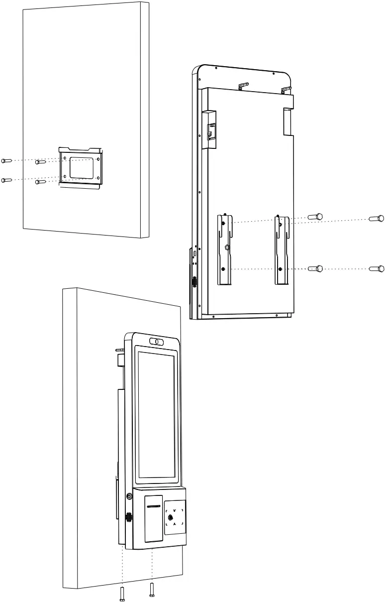
Wall Mount Bracket Installation
- Drill holes on the wall or other surface according to the mounting plate. It supposes each hole should has a diameter of 12mm and a depth of 45mm.
- Use four M8 self-tapping screws to secure the mounting plate on the wall.
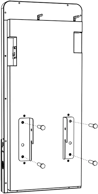
- Assemble the brackets on the holes on the back of the device and secure them with four M6 screws. Please note that the direction of how brackets put.
- Route the cables and connect to the device.
- Align the device with the mounting plate and brackets, then secure the device on the mounting plate with two M6 screws.
![]() Wall Mount Bracket is optional.
Wall Mount Bracket is optional.
Accessories
| Bracket | 2 Sets |
| Mounting Plate | 1 Set |
| M6 Screw | 6 Pieces |
| M8 Self-Tapping Screw | 4 Pieces |
Floor-Stand Installation
- Assemble the floor-stand on the base and secure them from the bottom with six M6 hexagon screws.
- Assemble two brackets on the holes on the back of the device and secure them with four M6 screws.
- Route the cables and connect to the device.
- Secure the device to the floor-stand with four M6 screws.
![]() Floor-Stand is optional.
Floor-Stand is optional.
NFC:Frequency 13.56 dBm
RF power:5.98dBuA/m@3m
Accessories
| Floor-Stand | 1 Set |
| Bracket | 2 Set |
| Base | 1 Set |
| M6 Hexagon Screws | 6 Pieces |
| M6 Screw | 8 Pieces |
Check-Out Desk Installation
- Base on floor-stand installation steps, secure check-out desk bracket to the floor-stand with six M6 screws.
- Secure check-out desk bracket to the check-out desk with four M6 screws.
- Assemble two baffles on the check-out desk with four M4 screws.
![]() Check-Out Desk is optional.
Check-Out Desk is optional.
Accessories
| Floor-Stand and Base | 1 Set |
| Check-Out Desk | 1 Set |
| Check-Out Desk Bracket | 1 Set |
| M6 Screw | 10 Pieces |
| M4 Screw | 4 Pieces |
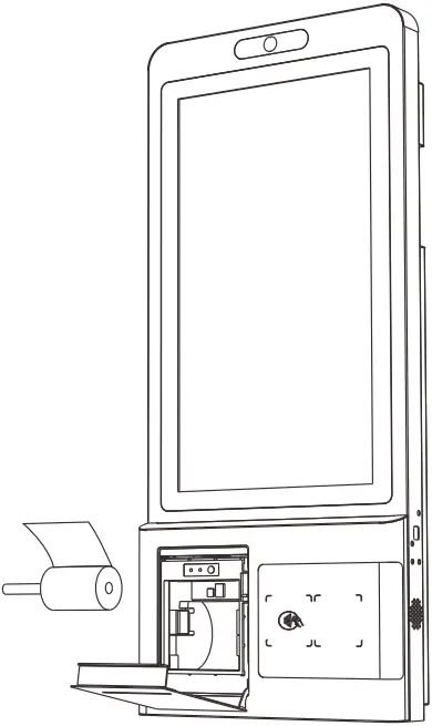
Printing Paper Replacement
1. Use the key to open the front cover of the printer.
2. Trigger to open the paper bin cover.
3. After loading the thermal paper , close the paper bin cover and printer front cover.
Tip: When you turn on the device at the first time, if the printer detects there is no paper, it will continue to beep until loading the paper.
4. Notes on the placement of print paper.
( 1 ) Put a roller in the middle of the paper.
( 2 ) Paper comes out at the top.
( 3 ) When placing the printing paper , pull the paper out a short way from the outlet and close the paper bin cover.
FCC Caution:
Any Changes or modifications not expressly approved by the party responsible for compliance could void the user’s authority to operate the equipment.
This device complies with part 15 of the FCC Rules. Operation is subject to the following two conditions: (1) This device may not cause harmful interference, and (2) this device must accept any interference received, including interference that may cause undesired operation.
IMPORTANT NOTE:
Note: This equipment has been tested and found to comply with the limits for a Class B digital device, pursuant to part 15 of the FCC Rules. These limits are designed to provide reasonable protection against harmful interference in a residential installation. This equipment generates, uses and can radiate radio frequency energy and, if not installed and used in accordance with the instructions, may cause harmful interference to radio communications. However, there is no guarantee that interference will not occur in a particular installation. If this equipment does cause harmful interference to radio or television reception, which can be determined by turning the equipment off and on, the user is encouraged to try to correct the interference by one or more of the following measures:
–Reorient or relocate the receiving antenna.
–Increase the separation between the equipment and receiver.
–Connect the equipment into an outlet on a circuit different from that to which the receiver is connected.
–Consult the dealer or an experienced radio/TV technician for help.
FCC Radiation Exposure Statement:
This equipment complies with FCC radiation exposure limits set forth for an uncontrolled environment. This equipment should be installed and operated with minimum distance 20cm between the radiator& your body.


