![]() ASME Lion
ASME Lion
User Guide
Ver 1.3 Copyright 2016 Axel Elettronica
www.axelelettronica.it
Downloaded from Arrow.com.
Copyright Notice and Disclaimer
All rights reserved. No parts of this manual may be reproduced in any form without the express written permission of Axel Elettronica.
Axel Elettronica makes no representations or warranties with respect to the contents hereof.
In addition, the information contained herein is subject to change without notice. Every precaution has been taken in the preparation of this manual. Nevertheless, Axel Elettronica assumes no responsibility for errors or omissions or any damages resulting from the use of the information contained in this publication.
Axel Elettronica does not assume any liability arising out of the application or use of any of its products or designs. Products designed or distributed by Axel Elettronica are not intended for or authorized to be used in, applications such as life support systems or for any other use in which the failure of the product could potentially result in personal injury, death or property damage.
Revision Sheet
| Release No. | Date | Revision Description |
| Ver 1.0 | 14/12/2016 | First Release |
| Ver 1.1 | 14/01/2017 | PDF error conversion fixed & General review |
| Ver 1.2 | 31/01/2017 | Fig. 2 and Fig. 5 changed |
| Ver1.3 | 11/2/2017 | MCU pin column added to table 4; Table 5,6,7 added |
Table 1: Document History
Chapter 1 Introduction
This document describes ASME Lion SoM (System On Module) based on an Atmel D21 Ultra-low-power microcontroller using the 32-bit ARM® Cortex®-M0+ processor.
The ASME Lion Board provides the following peripherals or modules:
- Crypto Authentication chipset
- Lora Module
- GPS Module with Embedded Antenna
- Bluetooth Low Energy (BLE) Interface
The ASME Lion Board is supported by the Arduino IDE for a fast and easy software development cycle (https://www.arduino.cc/en/Main/Software).
The software can also be developed using the Atmel Studio IDE commonly preferred by professional software engineers (http://www.atmel.com/Microsite/atmel-studio/).
Board Specifications
| Characteristics | Value |
| CPU Clock speed | 48MHz |
| Flash Memory | 256K |
| SRAM | 32K |
| Connector | 1 Power Jack 1 USB 1 Lora antenna 1 Li-Po Battery 1 SWD Debugger Arduino compatible PinOut |
| Board supply voltage | 6V — 24V CC |
| Operative Voltage | 3.3V |
| Temperature | -40°C to +85°C |
| Dimensions | 68×30 mm |
| RoHS status | Compliant |
Table 2: Board Specifications
Chapter 2 Hardware
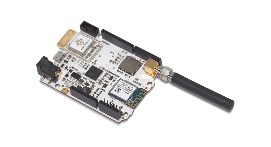
External View
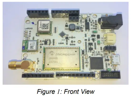
ASME Lion Block Diagram
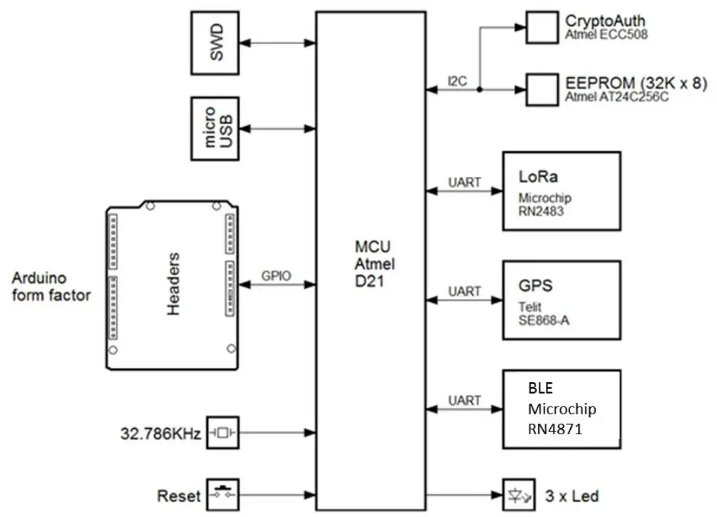
Figure 2: SmartEverything Block Diagram
ATMEL SAMD21Ultra low-power ARM® Cortex®-M0+ MCU
Atmel SAMD21 Ultra-low-power microcontroller using the 32-bit ARM® Cortex®-M0+ processor is the core of the entire board.
Memory
- 256KB in-system self-programmable Flash
- 8KB Flash Read-While-Write section
- 32KB SRAM Main Memory
- 8KB SRAM Low power Memory
Clock Frequency
- 32.768kHz crystal oscillator (XOSC32K)
Arduino compliance
- Digital i/o Pins: 20
- PWM Pins: all but 2 and 7
- USART: 2 (USB and TTL Digital)
- Analog Input Pins: 6, 12-bit DAC
- Analog Output Pins: 1, 10-bit DAC
- External Interrupts: All pins except pin 4
More information can be found on the ATMEL SAMD21 Data Sheet (See the link in Chapter 6 )
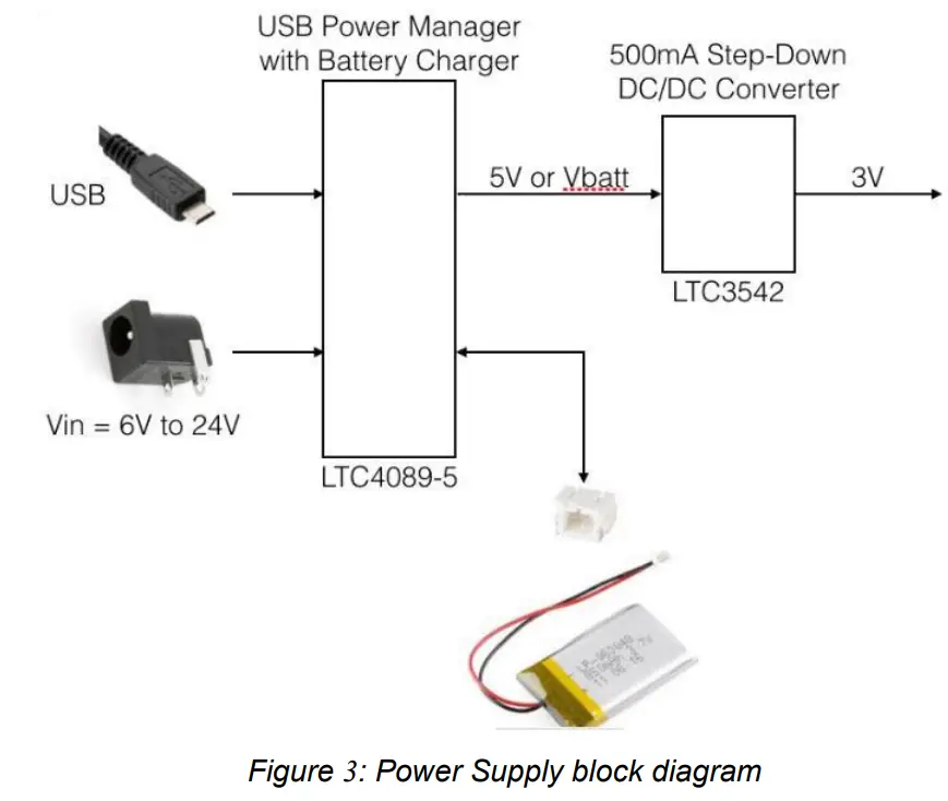
Power Supply Circuitry
The board can be powered by three different power supply sources:
- External Li-Po Battery
- A 6V to 24V input
- A 5V Mini USB connector
WARNING:
Li-Po batteries are charged at 4,2V with a current that is usually half of the nominal capacity (C/2). This board has a specialized chip that has a preset charging current of 350mAh. This means that the MINIMUM capacity of the Li-Po battery shall be 700 mAh. Smaller cells will be damaged by this current and may overheat, develop internal gasses and explode, setting the surroundings on fire.
All the components can work with the voltage range provided by the batteries, with the exception of the GPS module which requires at least 2.8V. For this reason, it is recommended to use an appropriate battery pack for prolonged use of the GPS.
| Name | Nominal | Description | Range |
| J10 | 3 V | Battery Power Supply | 1.4V to 3.2V |
| J12 | 6V to 24V | External Power Supply | 6V to 24V |
| USB | 5V | USB Port | 5V |
Table 3: Power Supply Connectors and ranges
Use Li-Ion battery Vnom = 3.7V, Vchrg = 4.2V Capacity >= 700 mAh
Microchip LoRa Module (RN2483)
The Microchip RN2483 is a Low-Power Long Range LoRa® Technology Transceiver Module, providing a low-power solution for long-range wireless data transmission.
The RN2483 module complies with the LoRaWAN Class A protocol specifications. It integrates RF, a baseband controller, and a command Application Programming Interface (API) processor. More information can be found on the relevant Data Sheet (See the link in Chapter 6 )
Main Features
On-board LoRaWAN protocol stack:
- ASCII command interface over UART
- Environmentally friendly, RoHS compliant
- European R&TTE Directive Assessed Radio Module
RF/Analog Features
- Low-Power Long-range Transceiver operating in the 433 MHz and 868 MHz frequency bands
- High Receiver Sensitivity: down to -146 dBm
- TX Power: adjustable up to +14 dBm high-efficiency PA
- Up to15km coverage at suburban and up to 5km coverage at urban area
Crypto Authentication Chip (ATMEL ATECC508A)
The ATECC508A is a member of the Atmel Crypto Authentication™ family of high-security hardware authentication devices. It has a flexible command set that allows to use it in many applications, including the following, among others:
- Anti-counterfeiting
- Protecting Firmware or Media
- Exchanging Session Keys
- Storing Data Securely
- Checking User Passwords
Device Features
The ATECC508A device includes an Electrically Erasable Programmable Read-Only Memory (EEPROM) array that can be used for key storage, miscellaneous read/write data, read-only, secret data, consumption logging, and security configuration.
Access to the various sections of memory can be restricted in a variety of ways, and the configuration can then be locked to prevent changes.
The ATECC508A features a wide array of defense mechanisms specifically designed to prevent physical attacks against the device itself or logical attacks against data transmitted between the device and the system.
Hardware restrictions on the way keys are used or generated provide further defense against certain styles of attack.
Access to the device is made through a standard I2C interface.
Each ATECC508A ships with a guaranteed unique 9-byte (72-bit) serial number. Using the cryptographic protocols supported by the device, a Host system or remote server can prove that the serial number is authentic and is not a copy. Serial numbers are often stored in a standard Serial EEPROM, which can be easily copied with no way for the Host to know if the serial number is authentic or if it is a clone. The entire serial number must be utilized to guarantee uniqueness.
Cryptographic Operation
The ATSHA204A supports a standard challenge-response protocol to simplify programming. In its most basic installation, the Host system sends a challenge (i.e. a number) to the device in the Client, which combines that challenge with a secret key by using the Message Authentication Code (MAC) command from the system and sends that response back to the system.
This basic operation can be expanded in many ways because of the flexible command set of the ATECC508A.
For a complete explanation of the possible Cryptographic Operations check the Data Sheet (See the link in Chapter 6 )
GPS Module with Embedded Antenna (Telit Jupiter SE868-A)
The Telit Jupiter SE868-A is a GPS Module designed to fully support GPS, QZSS, GLONASS and it is Galileo ready. It has an embedded SMT antenna and it is able to track GPS + GLONASS (and eventually Galileo) constellations simultaneously and to provide the position through the standard serial interface (UART).
The module software can increase the position accuracy by supporting:
- Ephemeris file injection (A-GPS)
- Satellite-Based Augmentation System (SBAS)
More information can be found on the relevant Data Sheet (See the link in Chapter 6 ).
Bluetooth Low Energy (Microchip RN4871)
The RN4871 is a small form factor, Bluetooth 4.2 Low-Energy module measuring just 9 x 11.5 x 2.1 mm. This fully-integrated module is designed for easy implementation into a broad range of applications. Supporting the latest Bluetooth standard, it delivers up to 2.5x throughput improvement and more secure connections vs. Bluetooth 4.1 based products. Developers can easily interface to the device via a standard UART interface, available on most Microcontrollers and Processors.
Characteristics
- FCC Certified Yes
- Min Temp Range -20C
- Max Temp Range +70C
- Op Voltage Min 1.9V
- Op Voltage Max 3.6V
More information can be found on relevant Data Sheet (See the link in Chapter 6 ).
The module on the board is equipped with the firmware able to communicate with the ATMEL SAMD21 MCU.
A suggested App for Android is
B-BLE (https://play.google.com/store/apps/details?id=com.billy.billylightblue&hl=it)
32Kx8 Bits EEProm (AT24C256C)
The Atmel® AT24C256C provides 262,144-bits of Serial Electrically Erasable and Programmable Read-Only Memory (EEPROM) organized as 32,768 words of 8 bits each.
The device’s cascading feature allows up to eight devices to share a common 2-wire bus.
The device is optimized for use in many industrial and commercial applications where low-power and low-voltage operations are essential
The device operates from 1.7V to 5.5V.
More information can be found on the relevant Data Sheet (See the link in Chapter 6 ).
Characteristics
- Low-voltage and Standard-voltage Operation ̶ VCC = 1.7V to 5.5V
- 400kHz (1.7V) and 1MHz (2.5V, 2.7V, 5.0V) Compatibility
- Write Protect Pin for Hardware Protection
- 64-byte Page Write Mode ̶ Partial Page Writes Allowed
- High Reliability ̶ Endurance: 1,000,000 Write Cycles ̶ Data Retention: 40 Years
EEprom Address
The EEPROM is mapped to the following I2C address 0x57
Board Interfaces and Connectors
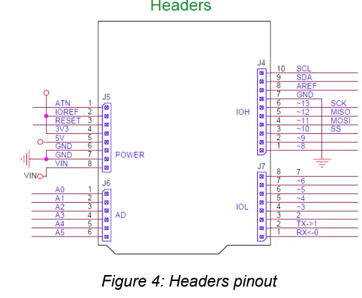
| Conn. | Pin | Description | Arduino pin label | Driven by |
| J4 | 1 | Digital I/O D8 / PWM | —8 | MCU Port PA06 |
| J4 | 2 | Digital I/O D9 / PWM | —9 | MCU Port PA07 |
| J4 | 3 | Digital I/O D10 / PWM SS | —10 | MCU Port PA18 |
| J4 | 4 | Digital I/O Dll / PWM MOSI | —11 | MCU Port PA16 |
| J4 | 5 | Digital I/O D12 / PWM MISO | —12 | MCU Port PA19 |
| J4 | 6 | Digital I/O D13 / PWM SCK | —13 | MCU Port PA17 |
| J4 | 7 | Ground pin | GND | |
| J4 | 8 | Analogue Reference (used by ADC) | AREF | MCU Port PA03 |
| J4 | 9 | 12C Interface SDA | SDA | MCU Port PA22 |
| J4 | 10 | 12C Interface SCL | SCL | MCU Port PA23 |
| 15 | 1 | Digital I/O ATN | ATN | MCU Port PB06 |
| 15 | 2 | IOREF | ||
| 15 | 3 | Reset | RESET | |
| 15 | 4 | 3.3V | ||
| 15 | 5 | 5V | ||
| 15 | 6 | Ground pin | GND | |
| 15 | 7 | Ground pin | GND | |
| 15 | 8 | External Power Supply Input | VIN | |
| J6 | 1 | Analog I/O AO | AO | MCU Port PA02 |
| J6 | 2 | Analog I/O Al | Al | MCU Port PB08 |
| J6 | 3 | Analog I/O A2 | A2 | MCU Port PB09 |
| J6 | 4 | Analog I/O A3 | A3 | MCU Port PA04 |
| J6 | 5 | Analog I/O A4 | A4 | MCU Port PA05 |
| J6 | 6 | Analog I/O AS | AS | MCU Port PB02 |
| 17 | 1 | Digital I/O DO / Seriall (RX) | RX<-0 | MCU Port PAll |
| 17 | 2 | Digital I/O D1 / Seriall (TX) | TX->1 | MCU Port PA10 |
| 17 | 3 | Digital I/O D2 / PWM | —2 | MCU Port PA14 |
| 17 | 4 | Digital I/O D3 / PWM | —3 | MCU Port PA09 |
| 17 | 5 | Digital I/O D4 / PWM | —4 | MCU Port PA08 |
| 17 | 6 | Digital I/O D5 / PWM | —5 | MCU Port PA15 |
| 17 | 7 | Digital I/O D6 / PWM | —6 | MCU Port PA20 |
| 17 | 8 | Digital I/O D7 / PWM | —7 | MCU Port PA21 |
Table 4: Arduino Compatible Headers
| Description | Driven by |
| BLE TXD | MCU Port PB16 |
| BLE RXD | MCU Port PB17 |
| BLE RTS | MCU Port PB22 |
| BLE CTS | MCU Port PB23 |
| BLE P10 | I/O Expander GPIO4 |
| BLE Pll | I/O Expander GPIO5 |
| BLE P32 | I/O Expander GPIO6 |
| BLE P33 | I/O Expander GP107 |
| BLE RST | I/O Expander GPIO1 |
Table 5 BLE port description
| Description | Driven by |
| LORA TXD | MCU Port PB12 |
| LORA RXD | MCU Port PB13 |
| LORA RTS | MCU Port PB14 |
| LORA CTS | MCU Port PB15 |
| LORA GPIOO | MCU Port PB07 |
| LORA GPIO1 | MCU Port PB10 |
| LORA GPIO2 | MCU Port PB11 |
| LORA RST | I/O Expander GPIOO |
Table 6 LORA port description
| Description | Driven by |
| GPS TXD | MCU Port PAl2 |
| GPS RXD | MCU Port PA13 |
| GPS RST | I/O Expander GPIO2 |
| GPS FORCE ON | I/O Expander GPIO3 |
Table 7 GPS/GNSS port description
Chapter 3 Mechanical Information
Main components layout
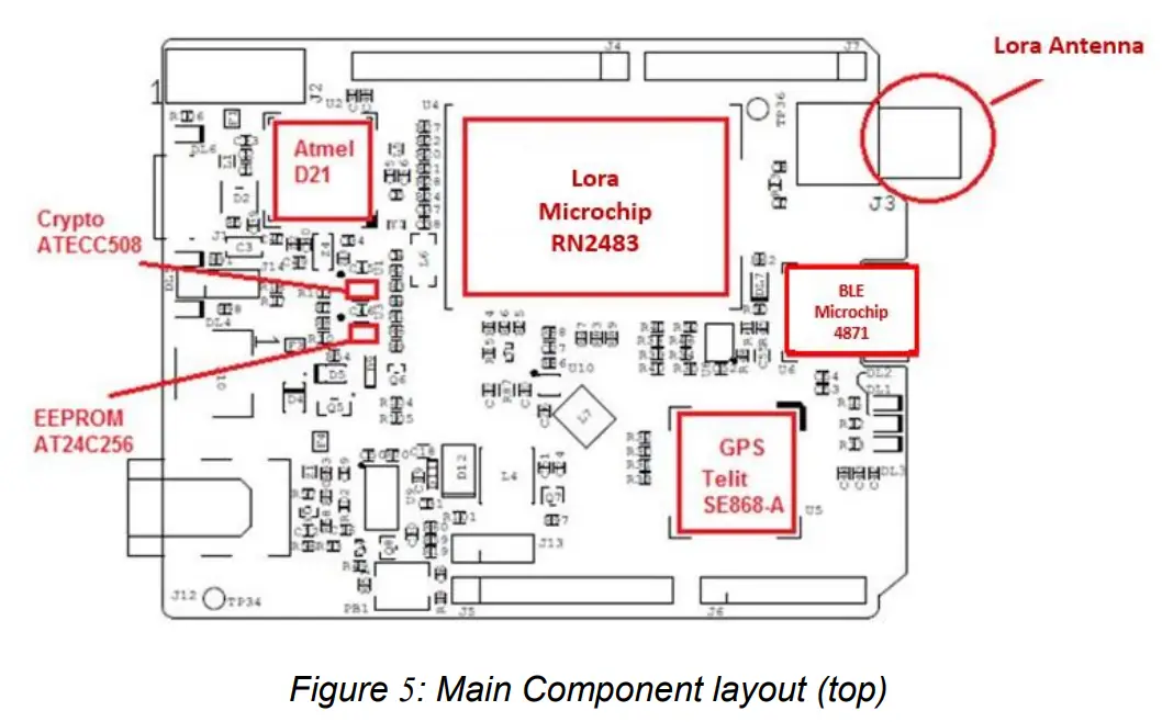
Mechanical Characteristics
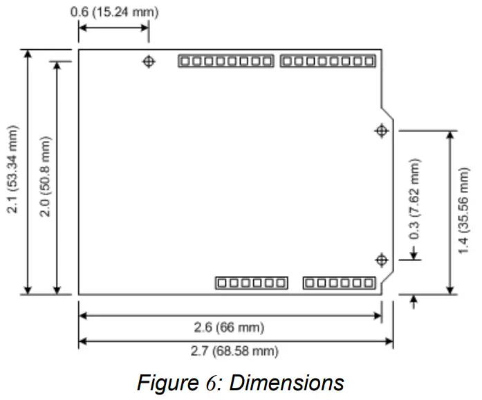
The maximum length and width of the Smarteverything Lion PCB are 2.7 and 2.1 inches respectively, with the USB connectors, power jack and antenna extending beyond the former dimension.
Three screw holes allow the board to be attached to a surface or case.
Note that the distance between digital pins 7 and 8 is 160 mil (0.16″), not an even multiple of the 100 mil spacing of the other pins.
This makes the SmartEverything Lion fully compatible with most shields designed for the Uno, Diecimila or Duemilanove.
Chapter 4 Software Development
The following chapters provide an overview of how users can develop their software and run it on the ASME Lion board.
There are two main ways to develop a software, load and debug it on the card:
- Using the Arduino IDE and Sketch Projects
- Using the Atmel Studio and Standard C/C++ language
When developing a software running on a microcontroller, having some tools to easily debug the code and fix what does not work as expected is really important.
The possibility to use an external debugger like the Atmel-ICE (http://www.atmel.com/tools/atatmel-ice.aspx) is available.
Chapter 5 Getting Started with Arduino IDE and Sketch Projects
Tools
The following tools are needed:
- Arduino IDE (Release 1.6.4 or newer)
- USB cable
Setup the Environment
Download and install the Arduino IDE from the Arduino web site (See the link in Chapter 6 )
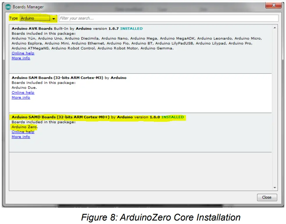
The first time you run the ArduinoIDE it is necessary to load the Arduino Zero & SmartEverything Core.
Click on the Tools Boards Boards Manager… menu entry
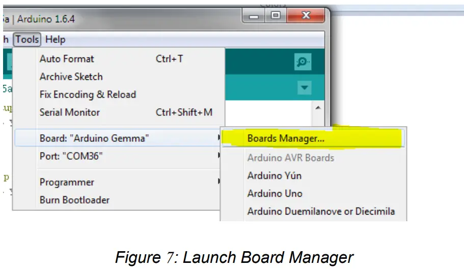
The two steps of installation shall be done as follows:
- Select from the “Type” combo Arduino and choose Arduino SAMD Boards in order to install the core of the Arduino Zero.

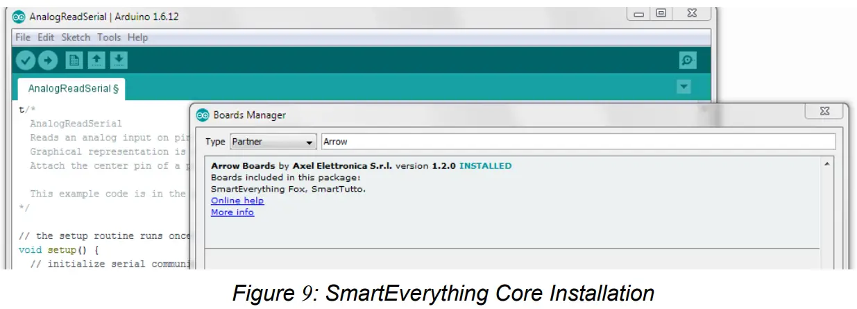
- Select from the “Type” combo Partner and choose the ARROW Boards in order to install the core of the SmartEverything.
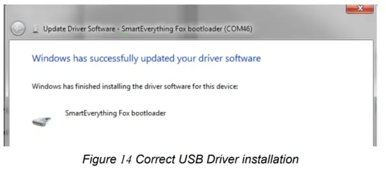
The installation procedure will automatically install all the necessary USB drives. Once the installation is completed, you will be able to connect the Board and start coding.
If the Driver installation process does not completed successfully, follow the steps described in Chapter 7 .
Compile the Example project
This procedure explains how to compile and download the code on the SmartEverything Lion board.
As every other Arduino board, the SmartEverything Lion has the basic examples code. To try those examples, just go to File->Examples and select one under the 01.Basics menu. 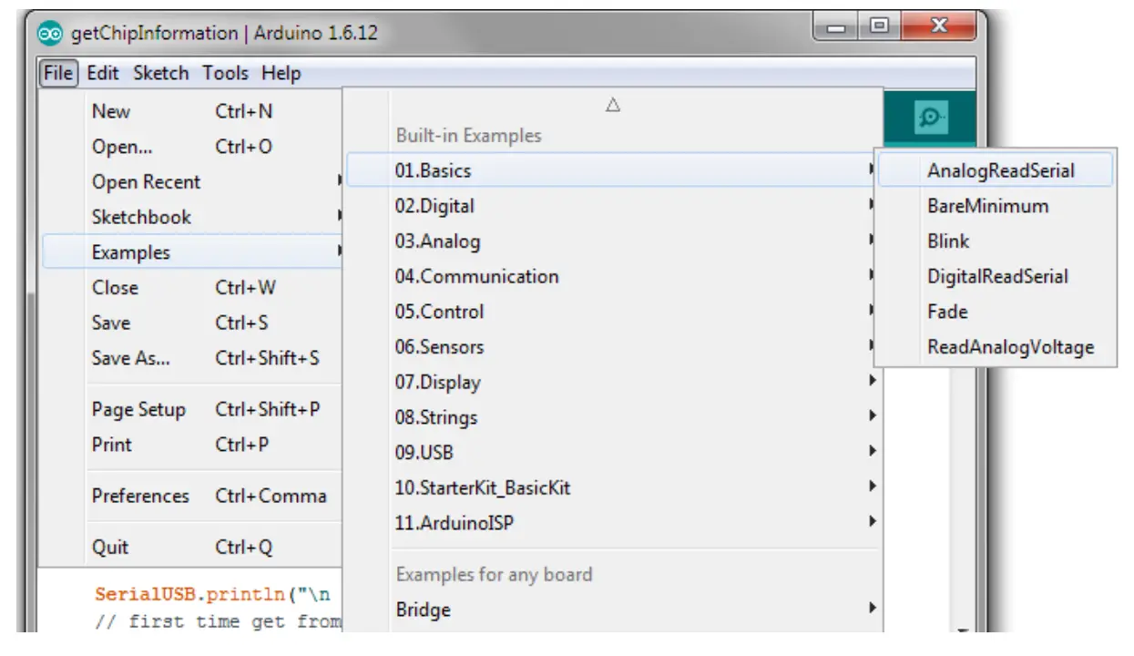
Run the software
Verify the code
Load the software on the Connect the SmartEverything Lion board. 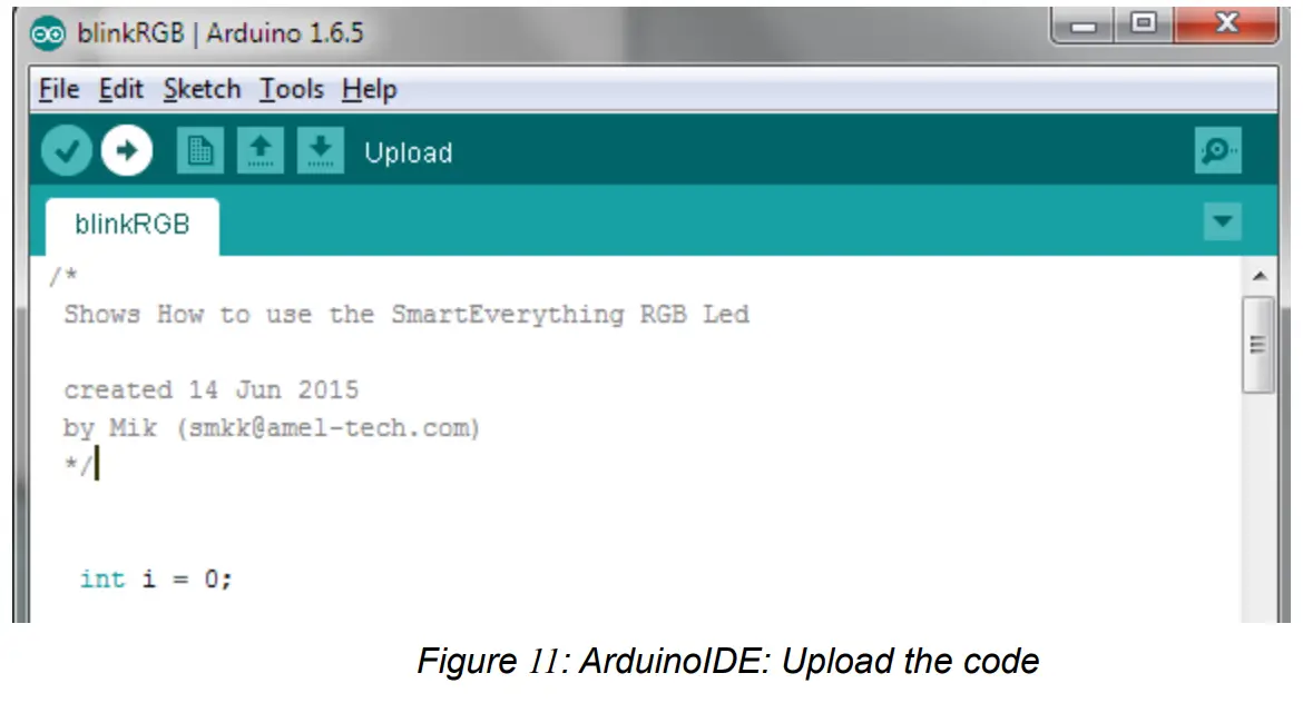
Importing the Lora SmartEverything Board Library
The SmartEverything Lion board will provide, a few days after its release on the market, some useful libraries to interface with some of its main components.
In order to include the Smart Everything library use the menu Sketch Include Library Manage Libraries. 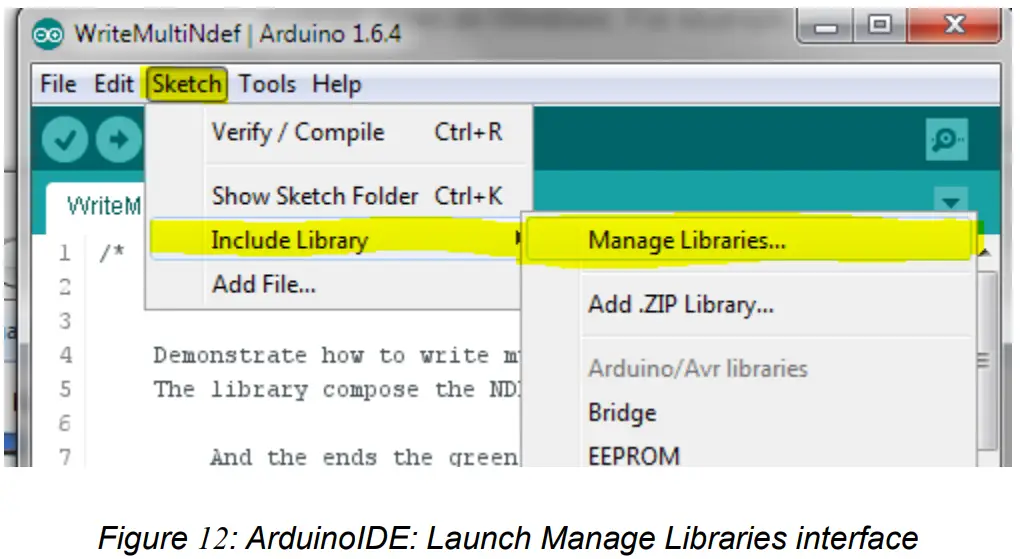
Once the Library Manager is started, you can filter the available libraries by writing SmartEverything, or the name of the component, in the right top text box, and then you can select the necessary library.
The procedure to download the other SmartEverything Lion libraries is identical. 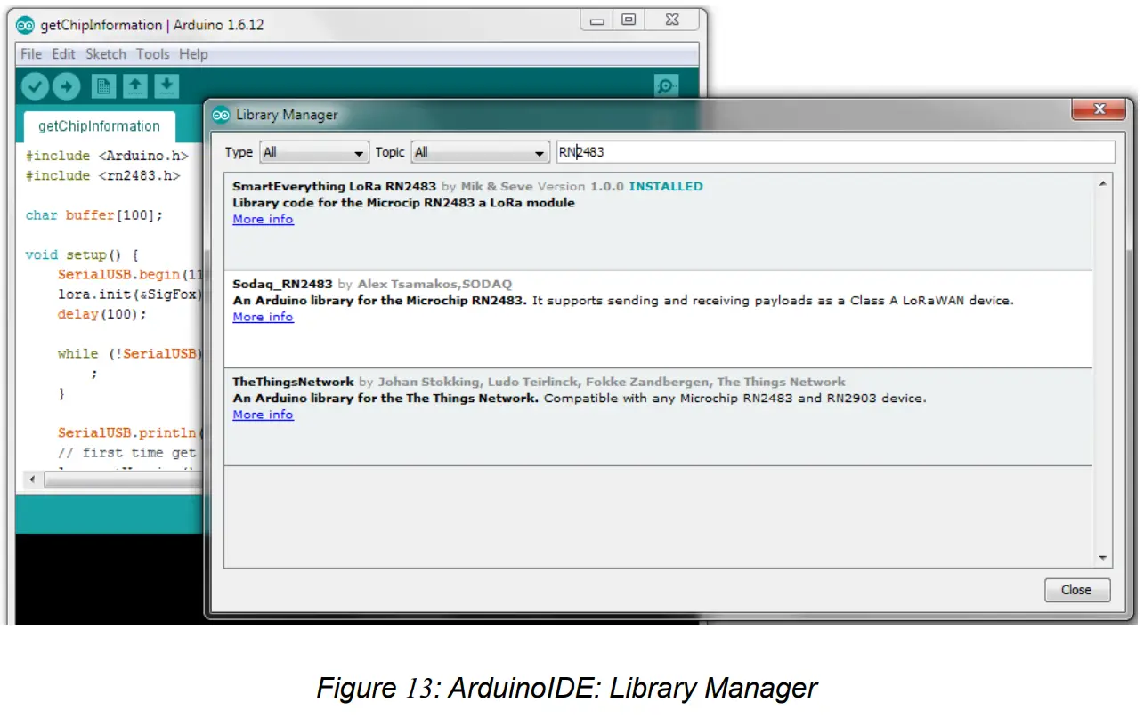
Another way to install the Library of the supported components is going to the GitHub repository and downloading the zip file.
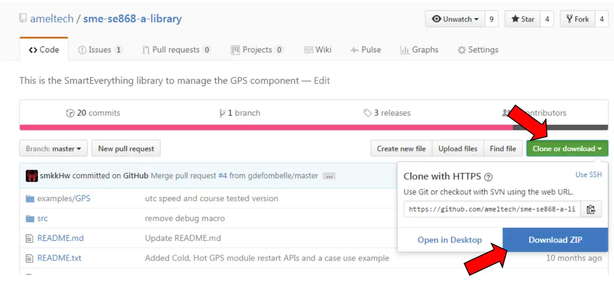
Once it is downloaded, go to the “include Library” menu and use the “Add . ZIP Library…item.
Official GitHub library repository
Here is the official repository where the zip file to download can be found:
- Lora Library (https://github.com/axelelettronica/sme-rn2483-library)
- GPS Library (https://github.com/ameltech/sme-se868-a-library)
- BLE Library (https://github.com/axelelettronica/sme-rn4870-library)
- EEProm Library (https://github.com/PaoloP74/extEEPROM)
The EEProm shall be initialized with these parameters new extEEPROM(kbits_256, 1, 64, 0x57);
Chapter 6 References and Useful Links
Data sheets
- ATMEL SAMD21 Ultra low-power ARM® Cortex®-M0+ MCU
http://www.atmel.com/Images/Atmel-42181-SAM-D21_Datasheet.pdf - Crypto Authentication Chip (ATMEL ATECC508A)
http://www.atmel.com/devices/atecc508a.aspx - Dynaflex 868Mhz Antenna (915/2)
- LoRa Module (Microchip RN2483)
http://www.microchip.com/wwwproducts/en/RN2483 - GPS Module with Embedded Antenna (Telit Jupiter SE868-A)
http://www.telit.com/products/product-service-selector/product-serviceselector/show/product/jupiter-se868-a/ - BLE Microchip RN4871(specification)
http://www.microchip.com/wwwproducts/en/RN4871 - E2Prom ATMEL (AT24C256C)
http://www.atmel.com/images/atmel-8568-seeprom-at24c256c-datasheet.pdf
Tools
- Arduino IDE
- Atmel Studio
Web Sites
- Axel Elettronica – www.axelelettronica.it
- Arduino – www.arduino.cc
- Atmel – www.atmel.com
- Microhip – http://www.microchip.com/
Chapter 7 Troubleshooting
Driver installation problems
It can happen that the installation of the driver does not automatically complete successfully. The drivers to manage the COM Port are not properly installed and the device is reported as an Unknown Device.
If this happens, it is necessary to install the driver manually.
The correct drivers can be found in the following directory.
C:\Users\<login name>\AppData\Local\Arduino15\packages\Arrow\hardware\samd\<installed Rel>\drivers.
ASME Lion User Guide
Ver. 1.3 – 11/02/2017
References
 Arduino - Home
 Empowering Innovation | Microchip Technology
-
atmel.com/devices/atecc508a.aspx
-
Smart | Connected | Secure | Microchip Technology
-
Smart | Connected | Secure | Microchip Technology
-
Empowering Innovation | Microchip Technology
-
microchip.com/wwwproducts/en/RN2483
-
microchip.com/wwwproducts/en/RN4871
 GitHub - ameltech/sme-se868-a-library: This is the SmartEverything library to manage the GPS component
-
GitHub - axelelettronica/sme-rn2483-library
-
GitHub - axelelettronica/sme-rn4870-library: The basic Library for the Microchip rn4870 BLE
-
GitHub - PaoloP74/extEEPROM: Arduino library to support external I2C EEPROMs.
-
B-BLE(BLE4.0 Scan) - App su Google Play
-
Software | Arduino


