AKO-145601 Electronic Expansion Valve Controller User Guide
Warnings
Using the unit not observing the manufacturer’s instructions may alter the appliance’s safety requirements. Only probes supplied by AKO should be used for the appliance to operate correctly.
The unit should be installed in a place protected from vibrations, water and corrosive gases, where the ambient temperature does not exceed the values indicated in the technical data.
For the reading to be correct, the probe should be used in a place without heat influences apart from the temperature you want to measure or control.
The probe and its cable should NEVER be installed in a conduit together with power supply, control or feeder cables.
The power supply circuit should be equipped with a switch for its disconnection of at least 2A, 230V,situated near the appliance.The cables are inserted into the rear part and should be H05VV-F or H05V-K type.The section to be used will depend on local regulations, but should not under any circumstances be less than 1 mm².
The cables for wiring the relay contacts should have a section of between 1 mm and 2.5 mm and wire for the one in common should 2 2 always have a section of 2.5 mm .Using of halogen- free cables is recommended. 2
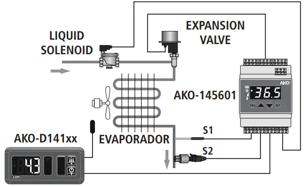
Probes 1 and 2 should be installed as close as possible to the evaporator output.There should not be any device between them (valves, peep-holes etc.) that could alter the reading.
The controllers are equipped with a port for connection of RS485 (MODBUS) data, which allows for remote management of these using an AKO-5012 web-server.
![]() IMPORTANT: AKO-14560 controllers can only share a MODBUS network with other AKO-14560 devices. The rest of AKO devices must be connected to an independent network. For further information, refer to the user manual available on www.ako.com
IMPORTANT: AKO-14560 controllers can only share a MODBUS network with other AKO-14560 devices. The rest of AKO devices must be connected to an independent network. For further information, refer to the user manual available on www.ako.com
Quick start
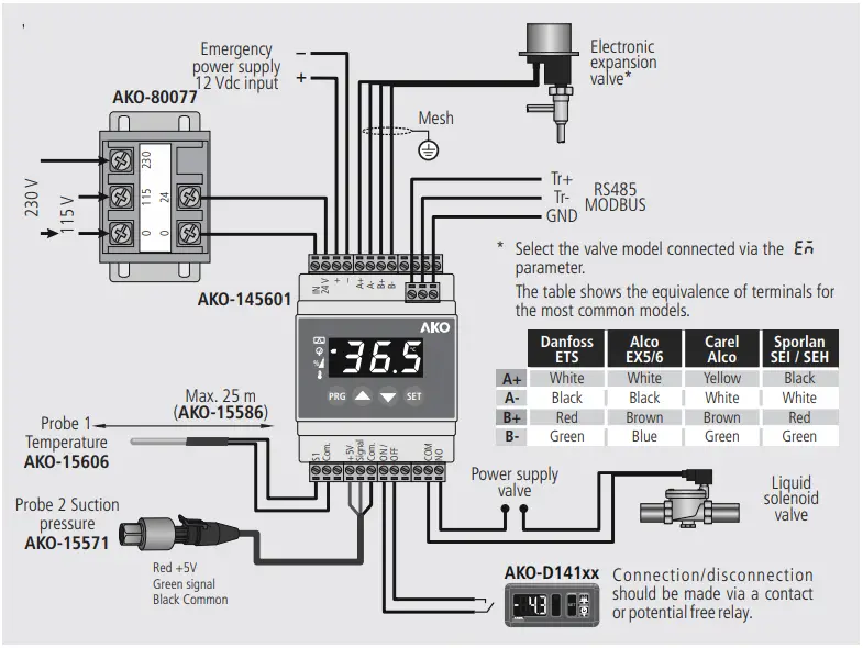
- Connect the controller according to the diagram in the ”wiring” section.
- Configure the rFt, EM and SH parameters according to the indications in the “Start up configuration”.
Wiring
Initial configuration
Prior to start-up, it is vital to configure the following parameters:
RFT: Select the type of refrigerant gas used in the installation from among the following compatible gases:
- R-22
- R-134A
- R-404A
- R-407C
- R-410A
- R-717
- R-23
- R-507C
- R-HFO1234ze
- R-744
- R-407A
- R-407F
- R-507A 13: R-245F
EM: Select the expansion valve model installed from among the following compatible models:
- Danfoss ETS 12.5 / 25B
- Danfoss ETS 50B
- Danfoss ETS 100B
- Danfoss ETS 250
- Danfoss ETS 400
- Alco Ex4
- Alco EX5
- Alco Ex6
- Alco EX7
- Alco EX8 (330 step/sec)
- Alco EX8 (500 step/sec)
- Sporlan SEI 0.5~11
- Sporlan SEI 1.5~20
- Sporlan SEI 30
- Sporlan SEI 100
- Sporlan SEI 175
- Carel E2V
SH: Configure the overheating set point
Description
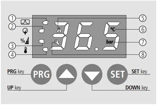
- The display shows the overheating value.
- The display shows the suction pressure value (Probe 2).
- The display shows the valve opening percentage.
- The display shows the temperature value.
- An alert is active
- The display shows the temperature value in ºC.
- The display shows the suction pressure value in bar
- The opening degree of the valve has been configured manually (Cor)
Operation
Keypad
 Pressing it for 5 seconds accesses the parameters programming menu.
Pressing it twice allows the regulation to be restarted in the event of an alarm. In the programming menu, you may return to level 1.
 In the programming menu, you may scroll around the different levels, or during the setting of a parameter,change its value.
 In the programming menu, you may scroll around the different levels, or during the setting of a parameter, change its value.
 Allows the displayed value to be changed (overheating, suction pressure, expansion valve opening or temperature) (only if the DM parameter = 0).
The programming menu allows you to move around the different levels and accept changes. Pressing it for 5 seconds exits the programming menu.
Adjustment of parameters
Using the programming menu, you will be able to configure the various parameters in order to adapt the controller’s operation to the needs of its installation.
In order to access the programming menu, press the PRG key for 5 seconds, or until the message ![]() is displayed. Using the
is displayed. Using the ![]() and
and ![]() keys enter the password (programmed into the
keys enter the password (programmed into the ![]() parameter) and press SET. Once entered correctly, the password will not be requested again for 30 minutes.
parameter) and press SET. Once entered correctly, the password will not be requested again for 30 minutes.
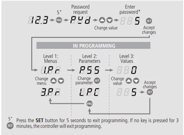
The default value of the password is 5.This may be changed using the PSS parameter
Table of parameters
The equipment’s operation functions are divided into 3 different groups.
The Def. column indicates the default parameters set in the factory. Temperature values are expressed in ºC. (Equivalent temperature in ºF) and the pressure values in bar (equivalent pressure in psi).
| Level 1 | Level 2 | |||||
| GROUP 1 | ||||||
| Description | Values | Min. | Def. | Max. | ||
| 1.Pr | Sh | Overheating set point | (K) | 3.5 | 10 | 30 |
| or | Initial opening for valve start up | (%) | 0 | 50 | 100 | |
| orE | Duration of initial start up opening | (Sec.) | 0 | 5 | 300 | |
| pro | Proportional gain | 0.1 | 3 | 99.9 | ||
| nE | Integral time | (Sec.) | 0 | 120 | 999 | |
| dEr | Derivative time | (Sec.) | 0 | 30 | 999 | |
| LSR | Lower overheating alarm 0: Deactivated 1: Automatic reset 2: Manual reset | 0 | 1 | 2 | ||
| LSS | Lower overheating alarm activation value | (K) | 0.5 | 3 | 30 | |
| LSC | Lower overheating alarm turn-on delay time | (Sec.) | 1 | 15 | 300 | |
| RPR | Lower overheating alarm deactivation time | (K) | 1 | 3 | 30.5 | |
| RPS | Maximum pressure alarm in probe 2 0: Deactivated 1: Automatic reset 2: Manual reset | 0 | 1 | 2 | ||
| Mps | Maximum pressure alarm activation value | (bar/psi) | -999 | 9 | 999 | |
| Mpr | Maximum pressure alarm turn-on delay time | (Min.) | 1 | 1 | 15 | |
| Mpc | Maximum pressure alarm deactivation time | (bar/psi) | -999 | 8 | 999 | |
| SM | Maximum overheating alarm 0: Deactivated 1: Automatic reset 2: Manual reset | 0 | 0 | 2 | ||
| SS | Maximum overheating alarm activation value | (K) | 10.0 | 30 | 40.0 | |
| Sc | Maximum overheating alarm turn-on delay time | (Min.) | 1 | 3 | 600 | |
| Sr | Maximum overheating alarm deactivation time | (K) | 7.0 | 27 | 37.0 | |
| PM | Freeze alarm 0: Deactivated 1: Automatic reset 2: Manual reset | 0 | 0 | 2 | ||
| PS | Maximum freeze alarm activation value | (ºC/ºF) | -100 | 0 | 200 | |
| Pc | Freeze alarm turn-on delay time | (Sec.) | 5 | 30 | 200 | |
| Pr | Maximum freeze alarm deactivation time | (ºC/ºF) | -100 | 3 | 200 | |
| LPM | Lower pressure alarm in probe 2 0: Deactivated 1: Automatic reset 2: Manual reset | 0 | 0 | 2 | ||
| LPA | Lower pressure alarm activation value | (bar/psi) | -999 | 0 | 999 | |
| LPS | Lower pressure alarm turn-on delay time | (Sec.) | 5 | 5 | 200 | |
| LPC | Lower pressure alarm deactivation time | (bar/psi) | 0 | 0.3 | 999 | |
| GROUP 2 | ||||||
| Description | Values | Min. | Def. | Max. | ||
| 2.Pr | pu | Pressure units 0: Bar 1: Psi | 0 | 0 | 1 | |
| u | Temperature units 0: ºC 1: ºF | 0 | 0 | 1 | ||
| EM | Selection of expansion valve model connected 1: Danfoss ETS 12.5 / 25B 2: Danfoss ETS 50B 3: Danfoss ETS 100B 4: Danfoss ETS 250 5: Danfoss ETS 400 6: Alco EX4 7: Alco EX5 8: Alco EX6 9: Alco EX7 10: Alco EX8 (330 s/s) 11: Alco EX8 (500 s/s) 12: Sporlan SEI 0.5~11 13: Sporlan SEI 1.5~20 14: Sporlan SEI 30 15: Sporlan SEI 100 16: Sporlan SEI 175 17: Carel E2V |
1 |
1 |
17 | ||
| SA | Total steps for expansion valve* | 0 | 262 | 999 | ||
| DSP | Expansion valve speed* | 0 | 250 | 999 | ||
| GROUP 3 | ||||||
| Description | Values | Min. | Def. | Max. | ||
| .Pr | pss | Parameter access password | 0 | 5 | 999 | |
| r | Type of refrigerant gas used: 0: R-22 1: R-134A 2: R-404A 3: R-407C 4: R-410A 5: R-717 6: R-23 7: R-507C 8: R-HFO1234ze 9: R-744 10: R-407A 11: R-407F 12: R-507A 13: R-245F | 0 | 1 | 13 | ||
| PSh | Pressure probe range (Maximum) | (bar/psi) | -999 | 15 | 999 | |
| PSL | Pressure probe range (Lower) | (bar/psi) | -999 | -1 | 999 | |
| PSO | Pressure probe calibration (S2) | (bar/psi) | -19.9 | 0 | 19.9 | |
| SO | Pressure probe calibration (S1) | (ºC) | -19.9 | 0 | 19.9 | |
| R | Expansion valve opening speed limit | (%) | 0.1 | OFF | 99.9 | |
| UrL | Maximum expansion valve opening limit | (%) | 0 | 100 | 100 | |
| LrL | Lower expansion valve opening limit | (%) | 0 | 0 | 100 | |
| Reading delay for probes (S1 and S2) | (Sec.) | 0.1 | 1 | 10.0 | ||
| OR | Lower expansion valve forced opening value | (%) | 0.0 | OFF | 100 | |
|
DM | Display mode: 0: Displays options 1 to 4 sequentially 1: Overheating value (ºK) 2: Suction pressure value (Probe 2) 3: Valve opening (%) 4: Temperature value (Probe 1) 5: Overheating set point |
0 |
1 |
5 | ||
| ID | Communication direction | 1 | 1 | 128 | ||
| SP | Communication speed | (BPSx100) | 48 | 96 | 384 | |
| INI | Initial settings (enter password and press SET) | 0 | 0 | 999 | ||
The TST and DSP parameters are adjusted automatically when the expansion valve model is selected. They should only be changed by qualified staff. AKO is not responsible for any damage that may be inflicted on the installation.
Messages
| Description | |
| PS | Problem in the pressure sensor |
| ESD | Probe 1 not connected |
| ESC | Crossed temperature probe |
| RoP | Maximum Operation Pressure (MOP) alarm |
| LoP | Lower Operation Pressure (LOP) alarm |
| hS | Maximum overheating alarm |
| LS | Lower overheating alarm |
| FrR | Frost detection alarm |
| SEP | Regulation stopped by external thermostat (ON/OFF Input) |
| CRL | Expansion valve initialisation |
| CLE | Valve closing underway due to fault in the electricity supply (emergency power supply required) |
![]() IMPORTANT: In the event of an alarm or fault in any of the probes, the controller closes the liquid solenoid and expansion valve until the problem is solved.
IMPORTANT: In the event of an alarm or fault in any of the probes, the controller closes the liquid solenoid and expansion valve until the problem is solved.
Technical specifications
Power supply ……………………………………………………………..24 V~ +10% / -15%, 50/60 Hz
Working ambient temperature …………………………………………-10 to 50 ºC, moisture <90 %
Storage ambient temperature ………………………………………….-20 to 60 ºC, moisture <90 %
Relay solenoid valve ……………………………………………….. (EN60730-1: 2(2) A 250 V~ SPST)
No.of relay operations………………………………………………….EN60730-1:100.000 operations
Maximum voltage in the SELV circuits………………………………………………………………….20 V
Protection degree ……………………………………………………………………………………………..IP2X
2
Connections …………………………….Terminal to screw for cables with a section of up to 2.5 mm
Control device classification:Built-in assembly,with Type 1.B automatic operation action feature,
for use in clean situations,logical support (Software) class A and continuous operation.Degree of
contamination 2 acc.to UNE-EN 60730-1.
Double power input insulation,secondary circuit and relay output.
Rated pulse voltage ………………………………………………………………………………………2500 V
Pressure ball test temperature Accessible parts………………………………………………….75 ºC
Parts that position active elements………………………..125 ºC
Voltage and current declared by the EMC tests………………………………………………..207 V,17 mA
Radio interference suppression test current…………………………………………………………..270 mA
![]() For further information,refer to the user manual available on our website: www.ako.com
For further information,refer to the user manual available on our website: www.ako.com


 And Service Tool Instruction Manual")


