 ottobock 6A20=20 Shuttle Lock with Adjustment Screw
Product description


INFORMATION
Date of last update: 2022-03-03
- Please read this document carefully before using the product and observe the safety notices.
- Instruct the user in the safe use of the product.
- Please contact the manufacturer if you have questions about the product or in case of problems.
- Report each serious incident related to the product to the manufacturer and to the relevant authority in your country. This is particularly important when there is a decline in the health state.
- Please keep this document for your records.
Construction and Function
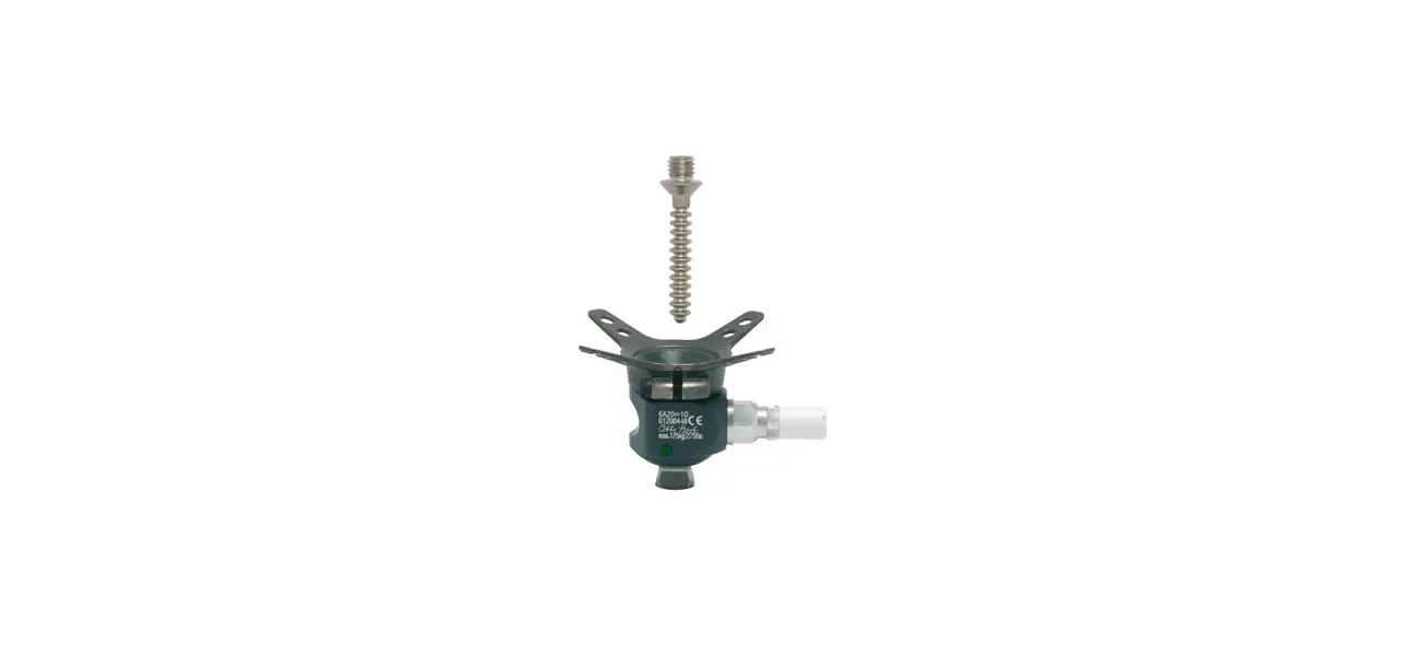
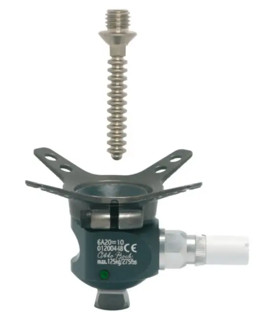
The 6A20=10, 6A20=20 shuttle lock serves to secure a suitable liner in the prosthetic socket. A lamination anchor is laminated into a the prosthetic socket. Then the shuttle lock is screwed into the lamination anchor.
Combination possibilities
This prosthetic component is compatible with Ottobock’s system of modular connectors. Functionality with components of other manufacturers that have compatible modular connectors has not been tested.
Intended use
Indications for use
The product is intended exclusively for lower limb endoprosthetic fittings.
Area of application
The maximum approved body weight is specified in the technical data (see page 14).
Environmental conditions
| Allowable environmental conditions |
| Temperature range for use: -10 °C to +60°C |
| Allowable relative humidity 0 % to 90 %, non-condensing |
| Unallowable environmental conditions |
| Mechanical vibrations or impacts |
| Perspiration, urine, fresh water, salt water, acids |
| Dust, sand, highly hygroscopic particles (e.g. talcum) |
Lifetime
Depending on the patient’s level of activity, the service life of the product is 3 to 5 years.
Safety
Explanation of warning symbols
CAUTION: Warning regarding possible risks of accident or injury.
General safety instructions
CAUTION: Risk of injury and risk of product damage
- Comply with the product’s field of application and do not expose it to excessive strain (see page 9).
- Note the combination possibilities/combination exclusions in the instructions for use of the products.
- Do not expose the product to prohibited environmental conditions.
- Check the product for damage if it has been exposed to prohibited environmental conditions.
- Do not use the product if it is damaged or in a questionable condition. Take suitable measures (e.g. cleaning, repair, replacement, inspection by the manufacturer or a specialist workshop).
- To avoid the risk of injury and product damage, do not use the product beyond the tested lifetime.
- To avoid the risk of injury and product damage, only use the product for a single patient.
- To prevent mechanical damage, use caution when working with the product.
- If you suspect the product is damaged, check it for proper function and readiness for use.
- Do not use the product if its functionality is restricted. Take suitable measures (e.g. cleaning, repair, replacement, inspection by the manufacturer or a specialist workshop).
Signs of changes in or loss of functionality during use
Among other factors, changes in functionality can be indicated by an altered gait pattern, a change in the positioning of the prosthetic components relative to each other and by the development of noises.
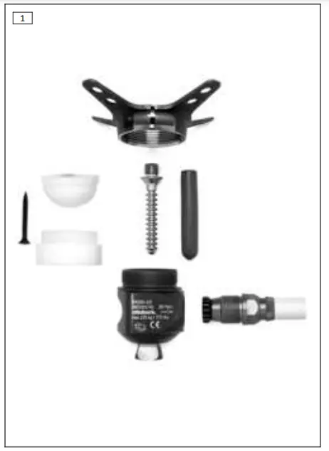
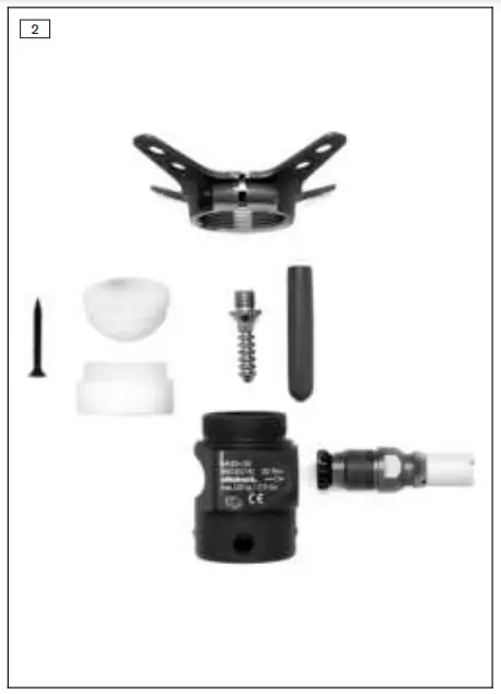
Scope of delivery
| Quant ity | Designation | Reference number |
| 1 | Instructions for use | – |
| 1 | Lamination anchor | 4R111=N |
| 1 | Shuttle lock housing | – |
| 1 | Ratchet unit | 6A52 |
| 1 | Pin | 6A20=10: 6Y13=1 |
| 6A20=20: 6Y13=2 | ||
| 1 | Plaster protection for pin | 5X440 |
| 1 | Dummy set (1 hemispherical dummy, 1 screw dummy, 1 plaster screw) | 5X55 |
| Only for 6A20=20: | ||
| 4 | Set screw | 506G3 |
Preparing the product for use
CAUTION
Incorrect alignment or assembly Risk of injury due to damaged prosthetic components
- Observe the alignment and assembly instructions.
CAUTION
Improper assembly of the screw connections Risk of injury due to breakage or loosening of the screw connections
- Clean the threads before every installation.
- Apply the specified torque values.
- Follow the instructions regarding the length of the screws and about how to secure the screws.
CAUTION
Improper processing of the anchor arms of the lamination anchor Risk of injury due to breakage of the anchor arms
- Only bend anchor arms of lamination anchors that are made of steel.
- Avoid bending the anchor arms too strongly or too frequently.
- Use the 711S4* bending irons for bending.
Preparing for socket fabrication
Required materials: Hemispherical dummy, plaster screw, 99B81* PVA bag
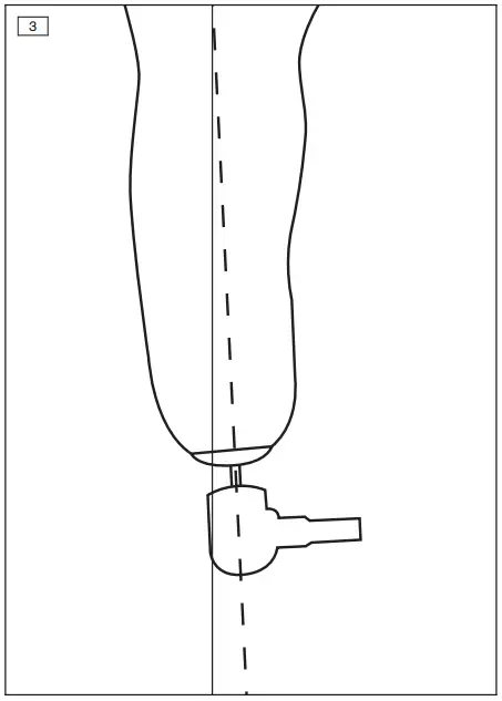
- NOTICE! Align the shuttle lock with the longitudinal axis of the residual limb to prevent unnecessary load and wear (2307228). Position the hemispherical dummy on the distal surface of the plaster model along the longitudinal axis of the residual limb and loosely secure it with the plaster screw.
- Pull a soaked PVA bag over the plaster model.
- Fabricate the prosthetic socket (see page 11).
Fabricating the prosthetic socket
INFORMATION The layup described in this document was approved for the maximum product user body weight. The prosthetist assumes full responsibility for any change to the layup.
Laminating a transfemoral socket
Required materials: 710D4 torque wrench, 711S4* bending iron, 616G6 Dacron felt, 623T3 Perlon stockinette, 616B1 carbon fibre cloth strap, 616G12 carbon fibre cloth, 616G4 fibreglass mat, 616G15 carbon fibre woven hose, 99B81 PVA bag, 617H119 Orthocryl lamination resin 80:20 PRO
- Cut 1 layer of Dacron felt to size and position it on the model.
- Pull 2 layers of Perlon stockinette over the model and tie it off on the hemispherical dummy.
- Position 2 layers of carbon fibre cloth strap (width: 5 cm) circularly 3 cm below the perineum.
- Medially and laterally, position 1 layer of carbon fibre cloth strap (width: 5 cm) respectively from the hemispherical dummy to the socket brim.
- Anterior and posterior, position 1 layer of carbon fibre cloth strap (width: 5 cm) respectively from the hemispherical dummy to the socket brim.
- Position 4 strips (approx. 5 cm x 3 cm) of fibreglass mat on the carbon fibre cloth strap to line the anchor arms.
- Position 2 layers of carbon fibre cloth (e.g. 15 cm x 15 cm) offset over the ischium containment.
- Pull 2 layers of Perlon stockinette over the model and tie it off on the hemispherical dummy.
- Screw the shuttle lock fully into the lamination anchor and tighten the screw of the threaded clamping (torque value: 10 Nm).
- Position the lamination anchor on the hemispherical dummy.
- Bring the lamination anchor arms to the correct a-p and m-l position. Never align the threaded clamping in the anterior or posterior direction.
- Optional: Adapt the anchor arms of the lamination anchor to the model with a bending iron.
- Replace the shuttle lock with the lamination dummy (see page 13).
- Wrap the clamping section of the lamination anchor with plasta tape to prevent contact with the lamination resin. This ensures even clamping.
- Place 2 layers of carbon fibre cloth (e.g. 15 cm x 15 cm) offset over the lamination anchor arms.
- Pull 2 layers of Perlon stockinette over the model and tie off below the cap screw of the lamination anchor.
- Pull 2 layers of carbon fibre woven hose over the model and tie off below the cap screw of the lamination anchor.
- Pull 2 layers of Perlon stockinette over the model and tie off below the cap screw of the lamination anchor.
- Pull a soaked PVA bag over the model.
- Complete the lamination process with Orthocryl lamination resin.
- After the lamination resin has cured, remove the lamination dummy.
Laminating the transtibial socket
Required materials: 710D4 torque wrench, cap screw, 711S4* bending iron, 99B81 PVA bag, 623T3 Perlon stockinette, 616B1 carbon fibre cloth strap, 699B1 fibreglass roving, 616G12 carbon fibre cloth, 616G4 fibreglass mat, 616G15 carbon fibre woven hose, 617H119 Orthocryl lamination resin 80:20 PRO
- Pull 2 layers of Perlon stockinette over the model and tie it off on the hemispherical dummy.
- Position 1 layer of carbon fibre cloth strap circularly around at the height of the MPT (mid-patella-tendon) point.
- Medially and laterally, position 1 layer of carbon fibre cloth strap (width: 5 cm) respectively from the hemispherical dummy to the socket brim.
- Anterior and posterior, position 1 layer of carbon fibre cloth strap (width: 5 cm) respectively from the hemispherical dummy to the socket brim.
- Position 4 strips (approx. 5 cm x 3 cm) of fibreglass mat on the carbon fibre cloth strap to line the anchor arms.
- Position 2 layers of carbon fibre cloth (e.g. 15 cm x 15 cm) offset around the hemispherical dummy on the distal end of the model.
- Pull 2 layers of Perlon stockinette over the model and tie it off on the hemispherical dummy.
- Screw the shuttle lock fully into the lamination anchor and tighten the screw of the threaded clamping (torque value: 10 Nm).
- Position the lamination anchor in the longitudinal residual limb axis on the hemispherical dummy.
- Bring the lamination anchor arms to the correct a-p and m-l position. Never align the threaded clamping in the anterior or posterior direction.
- Optional: Adapt the anchor arms of the lamination anchor to the model with a bending iron.
- Replace the shuttle lock with the lamination dummy (see page 13).
- Wrap the clamping section of the lamination anchor with plasta tape to prevent contact with the lamination resin. This ensures even clamping.
- Pull the fibreglass roving through the holes in the anchor arms and allow it to hang in a loop. If there are no holes, allow the fibreglass roving to hang around the anchor arms in a loop.
- Place 3 layers of carbon fibre cloth (e.g. 15 cm x 15 cm) offset over the lamination anchor arms.
- Pull 2 layers of Perlon stockinette over the model and tie off below the cap screw of the lamination anchor.
- Cut 1 piece of carbon fibre woven hose to size (1.3 times the length of the plaster model) and pull it over the model.
- Tie off the excess carbon fibre woven hose below the cap screw of the lamination anchor and pull it over the plaster model.
- Pull 2 layers of Perlon stockinette over the model and tie off below the cap screw of the lamination anchor.
- Pull on a soaked PVA bag.
- Complete the lamination process with Orthocryl lamination resin.
- After the lamination resin has cured, remove the lamination dummy.
Install the lamination dummy
- Tighten the screw of the threaded clamping to a point where the shuttle lock can still be screwed in and out.
- Unscrew the shuttle lock from the lamination anchor.
- Screw in the lamination dummy.
Final assembly
Installing the shuttle lock Required materials: 710D4 torque wrench, 636K13 Loctite® 241
- Screw the shuttle lock completely into the thread of the lamination anchor.
- The shuttle lock may be unscrewed from the thread by no more than 3/4 of a turn to align it.
- Secure the cap screw of the threaded clamping using Loctite® and tighten using the torque wrench (10 Nm).
Screwing in the ratchet unit
Required materials: 710D4 torque wrench, attachment for square drive socket wrench (1/4″ inside to 1/2″ outside), wrench socket
- Screw the ratchet unit into the shuttle lock (torque value: 20 Nm).
Use
CAUTION
Installation of the pin in a liner that is not approved Risk of injury due to loosening of the screw connection
- Only install the pin in liners with a metal thread and observe the specified tightening torque.
- Guide the pin into the lock in accordance with the instructions.
- Always verify that the pin is engaged in the lock before using the prosthesis.
- The liner and shuttle lock are connected to each other with the pin.
- The pin engages in the shuttle lock and holds the liner in place.
Putting on the Liner
1) Check the pin and liner for damage.
2) NOTICE! Align the pin with the longitudinal axis of the residual
limb to prevent damage.
Roll up the liner and place it on the end of the residual limb.
3) Unroll the liner onto the residual limb so that it has no wrinkles,
without shifting the soft tissue.
4) Check the fit and the alignment of the liner.
Donning the Prosthetic Socket
1) Slide into the prosthetic socket with the liner until the pin slides
into the opening of the shuttle lock.
2) Insert the pin fully into the shuttle lock.
3) Before using the prosthesis, verify that the pin is fully engaged in
the shuttle lock.
Doffing the Prosthetic Socket
- Press and hold the side button and pull the residual limb with the liner out of the prosthetic socket.
Maintenance
- A visual inspection and functional test of the prosthetic components should be performed after the first 30 days of use.
- Inspect the entire prosthesis for wear during normal consultations.
- Conduct annual safety inspections.
Legal information
All legal conditions are subject to the respective national laws of the country of use and may vary accordingly.
Liability
The manufacturer will only assume liability if the product is used in accordance with the descriptions and instructions provided in this document. The manufacturer will not assume liability for damage caused by disregarding the information in this document, particularly due to improper use or unauthorised modification of the product.
CE conformity
The product meets the requirements of Regulation (EU) 2017/745 on medical devices. The CE declaration of conformity can be downloaded from the manufacturer’s website.
Technical data
| Reference number | 6A20=10 | 6A20=20 |
| Weight [g] | 425 | 485 |
| System height [mm] | 25 | 79 |
| Build height [mm] | 43 | 61 |
| Material (lamination anchor) | Steel | |
| Material (shuttle lock) | Aluminium | |
| Max. body weight [kg] | 125 | |


