GAZCO Midi LED Electric Fire Range
GENERAL
DURING SERVICING OF THIS APPLIANCE IT MAY BE NECESSARY TO CUT CABLE TIES IN ORDER TO ACCESS AND REMOVE SOME OF THE PARTS.
THESE MUST BE REPLACED WHEN REASSEMBLING THE APPLIANCE.
WARNING: THE EFFECT SPINDLES ARE SHARP, PLEASE USE CAUTION WHEN SERVICING THIS APPLIANCE.
THIS APPLIANCE MUST ONLY BE SERVICED BY A SUITABLY QUALIFIED PERSON.
BEFORE UNDERTAKING ANY WORK ON THE APPLIANCE: SWITCH OFF THE APPLIANCE AND ISOLATE THE POWER SUPPLY ENSURING THERE IS NO POWER TO THE APPLIANCE.
Wait for at least 10 minutes until the appliance has cooled down.
Remote Handset Battery Replacement
Replace with 2 AAA batteries. Make sure the batteries are installed correctly in the remote control.
NOTE: The remote control has a Battery Status indicator (top right corner), after an extended period of displaying empty the LED screen will cease to function despite the handset still being able to send commands
Replace the batteries to restore display.
Maintenance of Motors
The motor used on the flame effect is pre-lubricated for extended bearing life and requires no further lubrication. However, periodic cleaning/vacuuming of the heater unit is recommended.
Resetting the Thermal Cutout Switch
The appliance is fitted with an Electronic Safety Control (E.S.). This is a safety device that switches off the fire if, the appliance overheats for any reason e.g. when covered.
If the heater stops operating whilst the flame effect continues normally, this indicates that the E.S. Control is in operation.
The E.S. Control can only be re-set after the appliance has cooled down.
To re-set the E.S:
Switch off the appliance (Manual On/Off switch) and leave for approximately 120 minutes.
Remove any obstruction to the fan heater outlet or other internal parts.
Switch on appliance and the E.S. Control will re-set. Ensure that the appliance is functioning correctly. If the E.S. Control operates again, the appliance should be checked by a competent Electrician.
Within 10 seconds, press the![]() button on remote. The coding is finished when 1 long beep sounds from the unit.
button on remote. The coding is finished when 1 long beep sounds from the unit.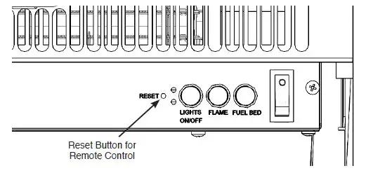
Resetting of the remote control is necessary if the appliance operates wrongly due to external interference signal and the remote control is not in use.
Open the back cover of the Remote.
Press the Reset button for 3 seconds and reset the coding. 
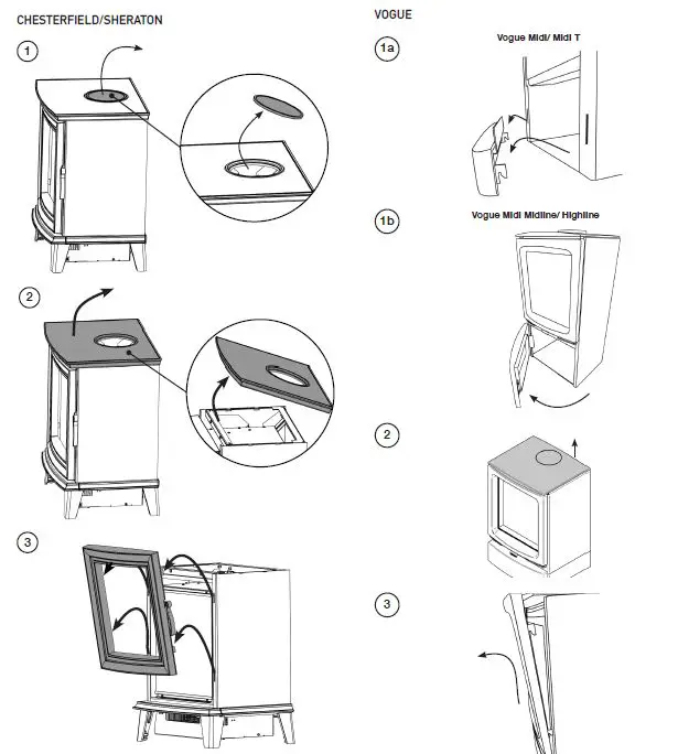
CHESTERFIELD/SHERATON
VOGUE MIDI/MIDI T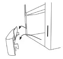
VOGUE MIDI T MIDLINE 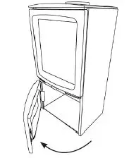
PAIRING THE REMOTE CONTROL TO THE APPLIANCE
Signal Code
The below operations should be carried out before coding when changing to a new remote or the unit cannot be controlled by the remote:
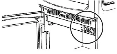
The reset button is located on the control panel located on the right-hand side of the viewing window.
Press the reset button for 3 seconds (a pen point may be needed) until 3 short beeps sound from the unit, release the button.
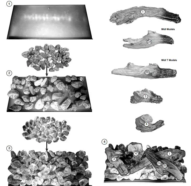
FUEL EFFECT
CRYSTAL ICE GLASS EFFECT
Evenly spread the small glass-effect crystals across the fuel bed.
It is not necessary to use all of the effect supplied.
Randomly space the large glass-effect crystals throughout the fuel bed.
Ensure some of the glass-effect crystals are touching and some are in isolation for the best results.
LOG EFFECT
The logs for the fuel bed are NOT individually labelled, the numbers are for reference information only. See Diagram on page 35/36.
- Evenly spread the clear pebble effect across the fuel bed.
- Randomly space the grey pebble effect throughout the fuel bed, partially covering the clear pebbles.
- Identify the logs using Diagram.
- If desired the Crystal Ice Glass Effect can be placed in between the log layout.
MAINTENANCE
CLEANING THE FUEL EFFECT
- Remove and wash the fuel effect to remove any dust particles Alternatively clean with a lint free duster.
- Ensure that the effect is dry before replacing.
- Replace the fuel effect, see Installation Instructions for layout.
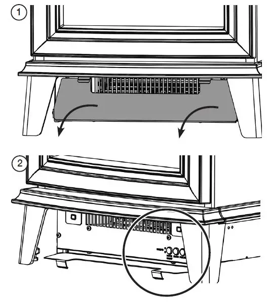
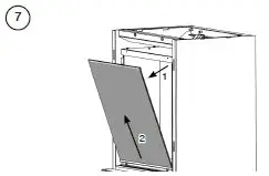
ACCESSING THE FUEL BED 


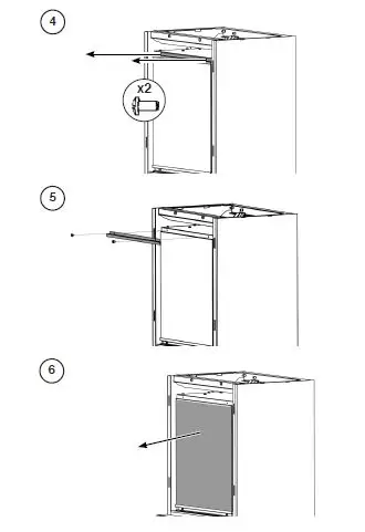
REPLACING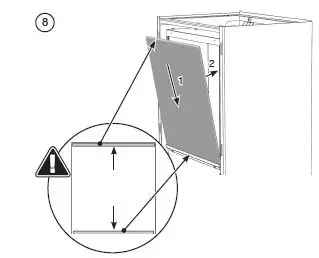
FUEL EFFECT – CRYSTAL ICE GLASS EFFECT
LOG SET – LOG LA YOU 
REMO VING THE LED LIGHT 
SPARE PARTS LIST
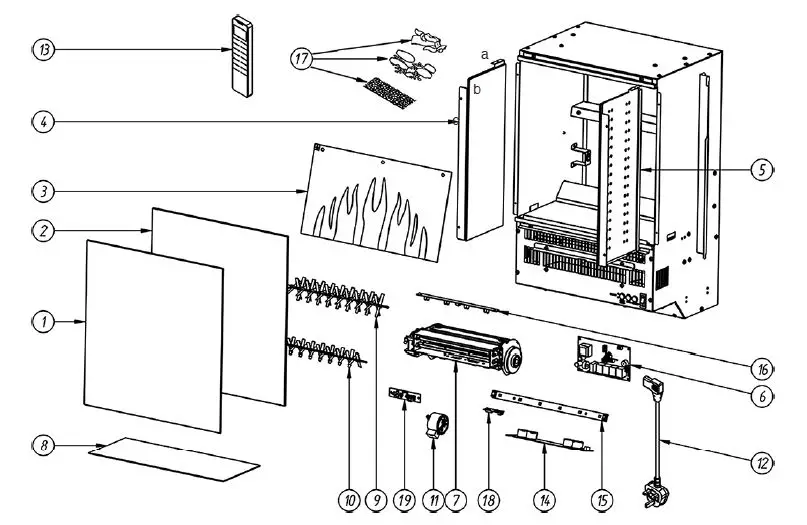
| MIDI/SHERATON/ CHESTERFIELD | MIDI T | MIDI/SHERATON/ CHESTERFIELD | MIDI T | ||||||||||||
| No. | UK | EU | Quantity | UK | EU | Quantity | No. | UK | EU | Quantity | UK | EU | Quantity | ||
| 1 | CE1943 | 1 | CE2078 | 1 | 12 | EL0714 | EL0542 | 1 | EL0714 | EL0542 | 1 | ||||
| 2 | CE1944 | 1 | CE2079 | 1 | 13 | EL0678 | 1 | EL0678 | 1 | ||||||
| 3 | PL0206 | 1 | PL0230 | 1 | 14 | EL0750 | 1 | EL0750 | 1 | ||||||
| 4 | GZ15135 | 1 | CE2080 | 1 | 15 | EL0751 | 1 | EL0751 | 1 | ||||||
| 5 | GZ15136 | 1 | CE2081 | 1 | 16 | EL0752 | 1 | EL0752 | 1 | ||||||
| 6 | EL0746 | 1 | EL0746 | 1 | |||||||||||
| 17a | CE2038 | 1 | CE2038 | 1 | |||||||||||
| 7 | EL0747 | 1 | EL0747 | 1 | |||||||||||
| 17b | CE2039 | 1 | CE2039 | 1 | |||||||||||
| 8 | PL0207 | 1 | PL0231 | 1 | |||||||||||
| 17c | CE2040 | 1 | CE2040 | 1 | |||||||||||
| 9 | EL0748 | 1 | EL0837 | 1 | |||||||||||
| 18 | EL0735 | 1 | EL0735 | 1 | |||||||||||
| 10 | EL0749 | 1 | EL0838 | 1 | |||||||||||
| 19 | EL0895 | 1 | EL0895 | 1 | |||||||||||
| 11 | EL0713 | 2 | EL0713 | 2 | |||||||||||
WIRING DIAGRAM
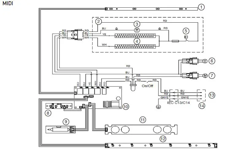
COLOUR CODES
- RD RED
- BU BLUE
- YE YELLOW
- WH WHITE
- BK BLACK
- BN BROWN
- GNYE GREEN & YELLOW
MIDI
- Top Light LED Board
- Heater Unit
- Fan Motor
- Heater
- Thermostat
- Flame Effect Motor
- Fuel Effect Motor
- Button Board
- Receiver Board
- PCB
- Flame Effect LED Board
- Fuel Effect LED Board
- Plug Connector Incoming AC Supply: 230V 50Hz required
- UK BS1363 Plug 13A BS1362 Fuse
SERVICING AND SUPPORT
To keep your appliance looking and performing at its best, it must be serviced annually. This service must be undertaken by a suitably qualified individual and your retailer can organise this for you. Alternatively, Gazco offer a manufacturers premium service with our friendly team of qualified engineers which can be booked at: www.gazco.com/support
FOR ENQUIRIES IN THE U.K (EXCLUDING NI):
Gazco Ltd, Osprey Road, Sowton Industrial Estate, Exeter, Devon, England EX2 7JG
Tel: (01392) 261900 E-mail: [email protected]


