
Netgear C6300v2 Cable Modem Router
Modem InformationDOCSIS 3.0 AC1750 Dual Band WiFi Modem 16×4 channel bonding To achieve Gigablast or Ultimate Classic speeds, a DOCSIS 3.1 modem is required | Highest Service LevelPreferred 150 |
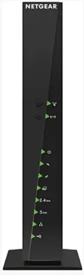
Front View
| The Netgear C6300v2 is a DOCSIS 3.0 device. After the cable modem is successfully registered on the network, the Power, Receive, Send, and Online indicators illuminate continuously to indicate that the cable modem is online and fully operational. | |
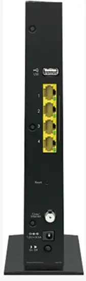
Back View
| The Netgear C6300v2 has the following ports available on the back of the modem.
| |
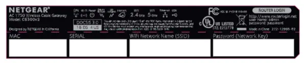
MAC Address
| MAC addresses are written as 12 digits containing both letters and numbers (0-9, A-F). A MAC address is unique. The first six characters of the MAC address are unique to the manufacturer of the device. |
Troubleshooting
The lights indicate the current status of your modem. To troubleshoot any connection problems, use the table below.
| Gateway Light | Status | Problem |
|---|---|---|
| WPS
| Off | No WiFi client is associated with the cable modem via WPS. Enable WiFi. |
| Blinking Green | None. The WPS button was pressed and WPS is now in discovery mode. LED blinks for up to two minutes. | |
| Solid Green | None. The WPS configuration was successful. | |
| WiFi
| Off | The WiFi card disabled. Enable WiFi by pressing and holding this button for two seconds. |
| Solid Green | None. WiFi is enabled. | |
| Power
| Off | No power. Verify all cable connections and try resetting the modem. |
| Solid Green | None. | |
| Downstream
| Blinking Green | Scanning for downstream channel. Verify all cable connections and reset the modem. |
| Solid Green | None. The connection from the computer to the internet is established on one or more channels. | |
| Upstream
| Off | The upstream channel is inactive. Verify all cable connections and reset the modem. |
| Blinking Green | Scanning for upstream channel. Verify all cable connections and reset the modem. | |
| Solid Green | None – Connection from the Internet to the computer established on one or more channels. | |
| Internet
| Off | No connection – Verify all cable connections and try resetting the modem. |
| Solid Green | None – WiFi modem operational. | |
| Blinking | None – WiFi modem receiving DHCP information. | |
| 2.4 GHz
| Solid Green | None – WiFi enabled at the 2.4 GHz frequency. |
| Off | WiFi radio disabled or not plugged in – To enable or disable the radio (2.4Ghz and 5 GHz), enable WiFi by pressing and holding the WiFi button for two seconds. | |
| 5 GHz
| Solid Blue | None – WiFi enabled at the 5 GHz frequency. |
| Off | WiFi radio disabled or not plugged in – To enable or disable the radio (2.4Ghz and 5 GHz), enable WiFi by pressing and holding the WiFi button for two seconds. | |
| Ethernet
| Off | A device is not connected to the Ethernet port on the back. Connect a device to the Ethernet port on the back. |
| Solid Green | None – A device is connected to the Ethernet port on the back. | |
| USB
| Off | A device is not connected to the USB port on the back. Connect a device to the USB port to back of the device. |
| Solid Green | None – A device is connected to the USB port on the back. |
Manufacturer Resources
For more detailed technical information on the C6300v2, refer to the C6300v2_All_MSOs_UM_Review_04Sept2018 [PDF]


