![]() EPC Series Pressure Switch
EPC Series Pressure Switch
User Manual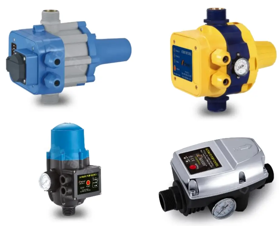
![]()
EPC Series Pressure Switch
Operation Manual Pressure Switch EPC Series EPC-1.1, EPC-2, EPC-4, EPC-4 with cable, EPC-5, EPC-5 with cable, EPC-5.1
5156551571
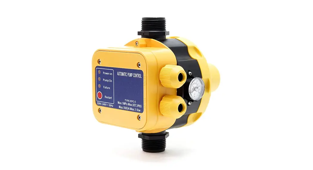
Illustration similar, may vary depending on model
Please read and follow the operating instructions and safety information prior to initial operation. Technical changes reserved! Illustrations, functional steps, and technical data may deviate insignificantly due to continuous further developments.
The information contained in this document may alter at any time without prior notice. No part of this document may be copied or otherwise duplicated without prior written consent. All rights reserved. WilTec Wildanger Technik GmbH cannot be held liable for any possible mistakes in this operating manual, nor in the diagrams and illustrations shown. Although WilTec Wildanger Technik GmbH has made every possible effort to ensure that this operating manual is complete, accurate, and up-to-date, errors cannot be ruled out entirely. If you have found an error or wish to suggest an improvement, we look forward to hearing from you.
Send us an e-mail to: [email protected]
or use our contact form: https://www.wiltec.de/contacts/
The most recent version of this manual in several languages can be found in our online shop: https://www.wiltec.de/docsearch
Our postal address is: WilTec Wildanger Technik GmbH Königsbenden 12 52249 Eschweiler Germany
To return your goods for exchange, repair, or other purposes, please use the following address. Attention! To allow for a trouble-free complaint or return, it is important to contact our customer service team before returning your goods.
Retourenabteilung WilTec Wildanger Technik GmbH Königsbenden 28 52249 Eschweiler Germany
E-mail: [email protected]
Phone: +49 2403 555920
Fax: (+49 2403 5559215)
https://www.XPOtool.com
The Tool Experts
Introduction
Thank you for choosing to purchase this quality product. To minimise the risk of injury, we ask you to always take some basic safety precautions when using this product. Please read this operating manual carefully and make sure that you understand it. Keep these operation instructions in a safe place.
Safety instructions
![]() CAUTION: The device is not intended for use by persons (including children) with impaired or limited physical, sensory, and mental abilities or lack of experience and/or real knowledge, unless they are supervised by a person responsible for their safety or follow the instructions made by this person on how to correctly use the device. Children should be supervised to ensure that they do not play with the device. Children must not clean or maintain the device.
CAUTION: The device is not intended for use by persons (including children) with impaired or limited physical, sensory, and mental abilities or lack of experience and/or real knowledge, unless they are supervised by a person responsible for their safety or follow the instructions made by this person on how to correctly use the device. Children should be supervised to ensure that they do not play with the device. Children must not clean or maintain the device.![]() ATTENTION:
ATTENTION:
- Perform a visual inspection of the device before every use. Do not use the device if the safety appliances are damaged or worn out. Never override safety regulations.
- Only use the device accordingly to the intended purpose stated in this manual.
- You are responsible for the safety of the working zone.
- If the cable or the plug is damaged due to external influences, the cable must not be repaired, but must be replaced with a new one. This work can only be carried out by an electrician.
- The voltage of 230 V AC indicated on the nameplate of the device must match the existent mains voltage.
- Never lift, carry, or fix the device by using the power cable.
- Make sure that the electrical plug connection is protected from flood and moisture.
- Before working on the device (maintaining, repairing, cleaning it), pull out the plug.
- The user is responsible for complying with local safety and mounting regulations. Ask an electrician, if necessary.
- In case of device failure, repairs can only be carried out by an electrician.
![]() WARNING: Read all safety precautions and instructions. Failure to obey the safety precautions and instructions might cause an electric shock, a fire, and/or severe injuries. Keep all safety precautions and instructions for future use.
WARNING: Read all safety precautions and instructions. Failure to obey the safety precautions and instructions might cause an electric shock, a fire, and/or severe injuries. Keep all safety precautions and instructions for future use.
Resistance
- The maximum temperature of the pumped liquid should not exceed +35 in continuous operation.
- The pump must not be used to pump flammable, gassing, or explosive liquids. The pump must not be used to pump other liquids, especially motor fuels, cleaning agent, or other chemical products.
Electrical connection
The electrical connection is made to an earthed socket 230 V ~ 50 Hz. Fuse min. 10 A.
Technical specifications
Refer to the name plate of the device concerning initial pressure and voltage.
| Max. current (A) | 10 |
| Max. operation pressure (㍴) | 10 |
| Max. temperature of liquids (℃) | 60 |
| Connections (㎜) | 32,89–33,25 (1″) external thread |
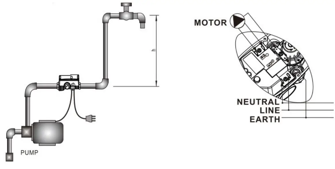
Operating mode and connection of the pressure switch
Notes:
- The circuit board must not be removed from the casing.
- The control of the pump comes with a connection diagram showing the correct installation. Take the appropriate marks into consideration; a wrong connection may cause a court circuit and destroy the control of the pump.
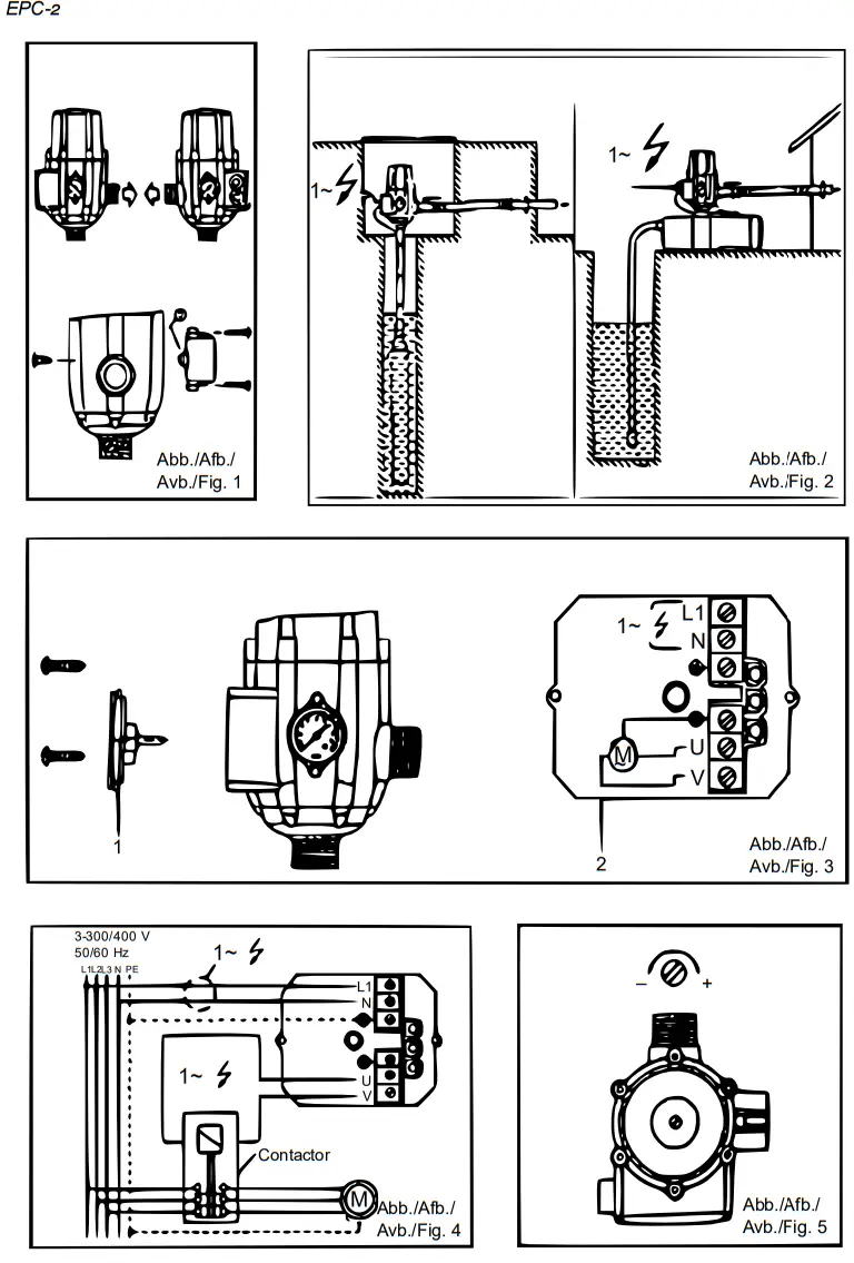
- For connection, only use an earthed three-conductor cable. The diameter of the cable must have a minimum of 7 mm and a maximum of 9.5 mm. Make sure to install the cable so that a portion of the cable is below the level of the fixing screws (s. fig.). One of the front ends of the cable must be inferior to the position of the fixing screw while de cable is connected to the mains as shown on the figure.
- The four screws of the casing and the coupling nut fixing the cables must be well tightened to avoid any penetration of water into the casing.
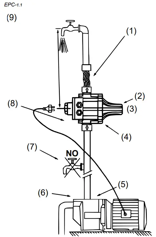
| EPC-1.1, EPC-5.1 | ||
| (3) Tighten the 4 screws. | (4) The two nuts fixing the cables must be attached. | (5) This part must be on a level inferior to the fixing nuts. |
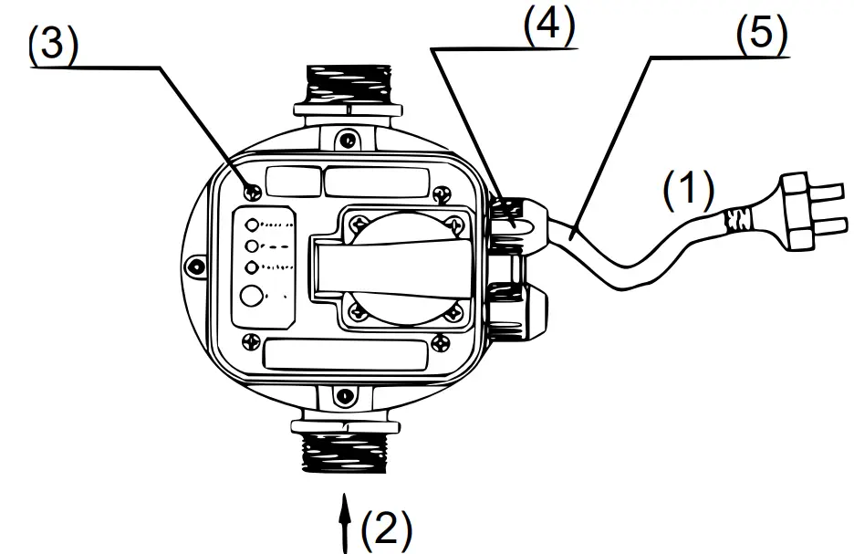
| № | Name | № | Name |
| 1 | Energy | 2 | Intake |
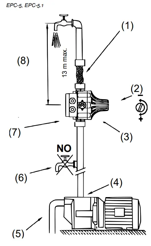
| EPC-5 | ||
| (3) Tighten the 4 screws. | (4) The two nuts fixing the cables must be attached. | (5) This part must be on a level inferior to the fixing nuts. |
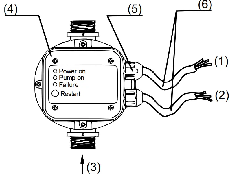
| № | Name | № | Name |
| 1 | Energy | 3 | Intake |
| 2 | Pump | ||
Operation
- With the pressure switch being connected to the mains, the green LED “Power On” will light up, and the orange LED “ON” (pump is working) will show that the pump has been switched on.
- The pump continues for about 12 s to fill the system with water and to reach the pressure required.
- After incorrect finishing of this cycle, the red LED “Failure” will light up. In that case, with the water tap open, press the restart button until the red LED goes off.
- Let the restart button go and close the water tap. The pump will stop as soon as the maximum pressure will have been reached.
Working principle
- The control of the pump is adjusted so that the entire process is automatic.
- Failures, e.g., a suction line blocked, lack of water, or comparable problems, are recognised automatically; then the pressure switch will activate the failure mode. The red LED “Failure” will light up; a stop signal is sent to the pump at the same moment to avoid damages caused by the pump running dry.
- After solving the problem, the system can be re-started with the help of the restart button.
Pressure regulation
- Before commissioning, check the initial pressure and mains voltage. The appropriate information is to be found on the name plate and instruction manual.
- The pressure switch needs to be installed in vertical position; when operating on an initial pressure of 1.5 bar, the position of the highest water tap/water outtake point must not exceed 13 m in relation to the pressure switch. The pump must have a pressure 0.8 bar superior to the initial pressure.
- If using variable settings, make sure that the initial pressure, height, and minimum pump pressure match the following schedule:
| Initial pressure (㍴) | Height (m) | Min. pump pressure (㍴) |
| x | H ≤ 10 × x – 2 | P = x + 0.8 |
| 1.5 | 13 | 2.3 |
| 2.2 | 20 | 3 |
| N9 | Model | Protection class |
| 51565 | EPC-1.1 | P 54 |
| 51566 | EPC-2 | IP 65 |
| 51567 | EPC-4 | |
| 51568 | EPC-4 with cable | |
| 51569 | EPC-5 | |
| 51570 | EPC-5 with cable | |
| 51571 | EPC-5.i |
Installation instructions
- It is advisable to connect the outtake of the device to the system with the help of a flexible hose.
- Safety valve preventing water from escaping in the case of a broken diaphragm
- Do not touch!
- It is indispensable to install the device with the arrows pointing upwards.
- The unit can be installed directly onto the pump or between the pump and water outtake.
- Pump pressure: The device has been set to a re-start pressure of 1.5 bar by the manufacturer. The pressure generated by the pump needs to be 0.8 bar higher than the pre-set pressure in normal operating conditions. Before operating the device, check the suction and make sure that the pump is primed.
- No water taps may be installed between the pump and unit.
- The unit as a non-return valve to avoid any pressure loss in the pipes.
- With the water column between the pump and highest water outtake exceeding 15 m, the unit cannot be installed directly onto the pump. It must be raised until the water column between the unit and highest water outtake does not exceed 15 m.
I.e., if the water column is at 20 m from the pump, the unit needs to be at a point 5 m over the pump.
- It is advisable to connect the outtake of the device to the system with the help of a flexible hose.
- The initial pressure is adjusted with the help of the screw at the upper part of the control.
- It is indispensable to install the device with the arrows pointing upwards.
- The unit can be installed directly onto the pump or between the pump and water outtake.
- With the water column between the pump and highest water outtake exceeding 13 m, the unit cannot be installed directly onto the pump. It must be raised until the water column between the unit and highest water outtake does not exceed 13 m. (5) Before operating the device, check the suction and make sure that the pump is primed.
- No water taps may be installed between the pump and unit.
- The unit as a non-return valve to avoid any pressure loss in the pipes.
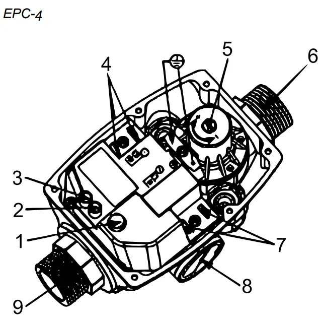
| N0 | Name |
| 1 | Reset button |
| 2 | Dry-run display |
| 3 | Voltage display |
| 4 | Pump connection |
| 5 | Pressure regulation |
| 6 | Outlet connection |
| 7 | Power connection |
| 8 | Intake connection |
| 9 | Pressure display |
 In case the pressure switch activates the error mode “Dry running” despite of water being inside the system, turn the pressure regulation screw five times counter-clockwise.
If the pump does not re-start, turn the screw five times clockwise to increase the operating pressure.
Wiring diagram for connection of different pump motors to pressure switch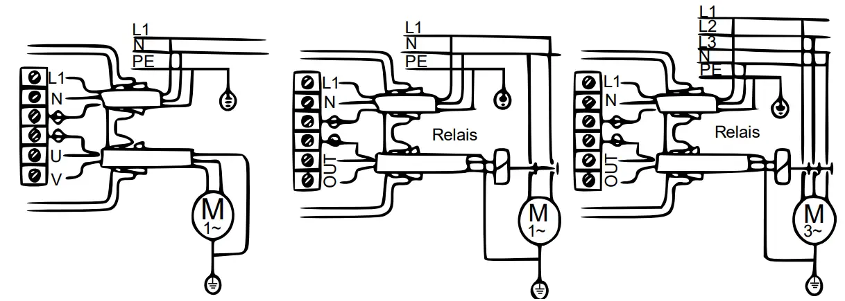
| Wiring diagram for monophase 220 V pumps up to 0.55 kW/1.1 kW. | Wiring diagram for monophase 220 V pumps over 0.55 kW/1.1 kW — control via 2phase relay (contactor); choose of relay depending on pump power, max. 4 kW or 5.5 hp. | Wiring diagram for three-phase pumps — control via 3-phase relay (contactor); choose of relay depending on pump power, max. 4 kW or 5.5 hp. |
Possible errors and solutions
| Problem | Dysfunction of pressure switch | Other dysfunction |
| Pump does not start. | Circuit board damaged | Missing voltage |
| Pump defect | ||
| Mixed-up electric cables | ||
| Pump does not stop. | Circuit board damaged | There is a leak with a loss supe1 rior to Ymtn. |
| Flow detector trapped in the up- per position | ||
| Reset button blocked | ||
| Pump has not enough pressure | ||
| Intermittent operation of pump | Circuit board damaged | There is a leak with a loss inferior 1 to %min. |
| Pump has not enough pressure | ||
| Pump blocked | Circuit board damaged | No water |
| The pump generates less water than required for start. | Suction impossible/blocked |
Regulations for waste disposal
The Waste Electrical and Electronic Equipment Directive (WEEE Directive, 2012/19/E ) of the E was implemented in the German law related to electrical and electronic equipment and appliances.
All WilTec electric devices that fall under the WEEE directive are labelled with the symbol of a crossedout wheeled rubbish bin. This symbol indicates that this electric device must not be disposed of with the domestic waste.
WilTec Technik GmbH is registered with the German registration authority EAR (Stiftung ElektroAltgeräte Register) under the WEEE-registration number DE45283704.
Disposal of used electrical and electronic devices (intended for use in the countries of the European nion and other European countries with a separate waste collection system for these devices). The symbol on the packaging or the product itself indicates that this product must not be treated as normal domestic waste but must be disposed of at a recycling collection station for electrical and electronic waste. By disposing of this product correctly, you contribute to the protection of the environment and the health of your fellow people. Inappropriate disposal threatens the environment and health. Material recycling helps to reduce the consumption of raw materials.
Additional information about the recycling of this product can be provided by your local commune, the municipal waste disposal facilities, or the store where you purchased the product.
Address:
WilTec Wildanger Technik GmbH
Königsbenden 12 / 28
52249 Eschweiler Germany
![]() Important Note:
Important Note:
Reproduction and any commercial use (of parts) of this operating manual, requires a written permission of WilTec Wildanger Technik GmbH.
https://www.XPOtool.com
The Tool Experts
Item 5156551571


