AVENTICS 5610219900 EP-Pressure Controller
Instructions
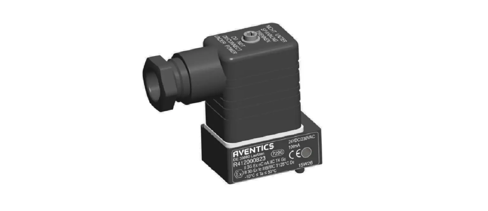
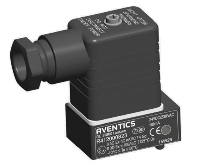
EP-Pressure Controller ED07 290psi VDS
This short instruction describes all operator control elements as LED and switches of the VDS pressure control valve ED07. For further information please refer to description 5610219900. This manual is available at AVENTICS and must be read thoroughly before installing and initial start-up of the module.
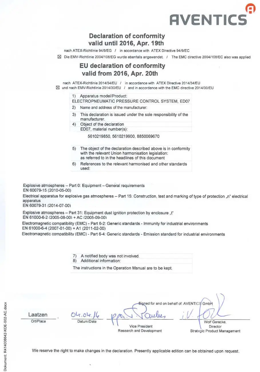
This device fulfils the category 3G and 3D according to ATEX directive 2014/34/EU. If the device is used in potentially explosive atmospheres attention has to be paid for the corresponding themes in the device description.
LED-Diagnosis
| Plate | Color of LED | Meaning |
| OK | green | VDS communication OK |
| ERR | red | VDS communication NOT OK |
| 24V | green | Power supply valve |
| 24V | green | Power supply interface |
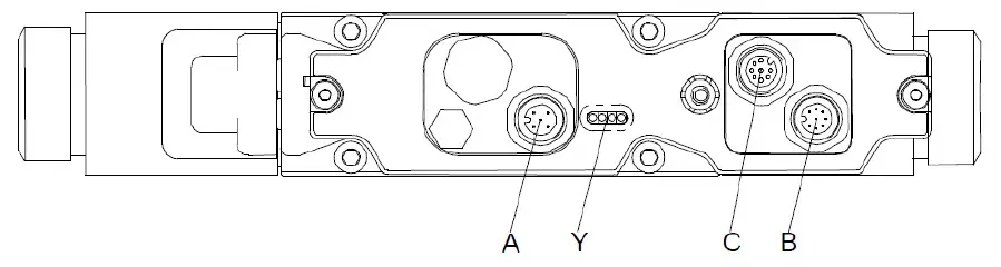
Y: Status LED
Electrical Connections
A: Power supply
B: Data input VDS C:
Data output VDS
| Pin 1 | 24V Valve (ext. fuse M 2,5A) |
| Pin 2 | 0V Valve |
| Pin 3 | n.c. |
| Pin 4 | n.c. |
| Pin 5 | FE |
A: Power supply
The 0V of the pressure control valve has to be connected directly with the 0V of the Bus module. The pressure control valve is defined as equipment with low energy. It has to be supplied with electrical power from a power pack with over- voltage protection according to standard DIN EN 60079-15: 2011, paragraph 13.
Control Data
The Control data are described in the device description.
Subject to alternation. Printed in Germany. No parts of this edition may be reproduced without our prior permission.
R499050039-DAT-001-AE
Internet, http://www.aventics.com
AVENTICS GmbH Ulmer Str. 4
D-30880 Laatzen GERMANY
Tel. +49(0)511/2136-0
Fax. +49(0)511/2136-269


