CORDIVARI 1 XL Coated Domestic HOT Water Calorifier Instruction Manual
APPLICATION
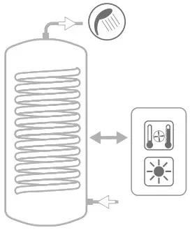
Production and storage of domestic hot water (DHW). All the connections are aligned on the front and on the back for quick and easy installation.
MATERIAL
Mild steel Polywarm® coated (Attestation ACS – SSICA – EN 16421 – WRAS)
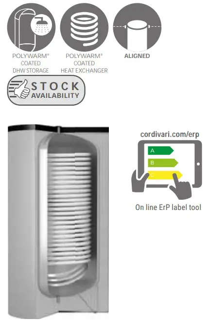
HEAT EXCHANGER
Mild steel Polywarm® coated heat exchanger.
INSULATION
HARD: High thermal insulation with ecological polyurethane hard foam. SOFT: NOFIRE® polyester fl eece 100% made of recyclable material, with high thermal insulation. Fireresistance class B-s2d0 according to EN 13501. HARD FOAM (CLASS “A” MODELS): rigid polyurethane foam for high thermal insulation with a vacuum sheet of highly insulating material. Grey PVC external lining.
CATHODE PROTECTION
Magnesium anode.
DRAIN
External confl uence through drain connection.
GASKET- FLANGE PLATE
Silicone gaskets suitable for water intended for human consumption (tested according to 98/83/CE), max temperature up to 200°C. Mild steel inspection fl ange plate with Polywarm® and connection for electric heater.
WARRANTY
5 years (See general sales conditions and warranty)
ACCESSORIES AND SPARE PARTS
See Accessories section for the entire list.

| Model | INSULATION | [m2] | |
| 200 | 3104162330011 | 2 | B |
| 300 | 3104162330012 | 3,4 | B |
| 400 | 3104162330013 | 4,4 | C |
| 500 | 3104162330014 | 5,4 | C |
| 800 | 3104162330015 | 6,0 | B |
| 1000 | 3104162330016 | 6,5 | B |

| Model | insulation | ||
| 800 | 3104162320007 | 6,0 | C |
| 1000 | 3104162320008 | 6,5 | C |

| 200 | 3104162330051 | 2 | A |
| 300 | 3104162330052 | 3,4 | A |
| 500 | 3104162330053 | 5,4 | A |
ACCESSORIES
ELECTRIC IMMERSION HEATERS
 | MONOPHASE | |||
| 1,5 kW | 2 kW | 3 kW | ||
| 5240000000051 | 5240000000052 | 5240000000053 | ||
| Mod. | Heated volume by electric immersion heater [lt] | Ignition time from 10 °C to 45 °C with electric immersion heaters [min] | ||
| 200 | 159 | 285 | 214 | 142 |
| 300 | 235 | 421 | 316 | 210 |
| 400 | 353 | 632 | 474 | 316 |
| 500 | 413 | 741 | 555 | 370 |
| 800 | 668 | 1197 | 898 | 598 |
| 1000 | 874 | 1565 | 1174 | 783 |
THREEPHASE | ||||
| 4 kW | 5 kW | 6 kW | 9 kW | 12 kW |
| 5240000000047 | 5240000000048 | 5240000000049 | 5240000000050 | 5240000000031 |
| Ignition time from 10 °C to 45 °C with electric immersion heaters [min] | ||||
| // | // | // | // | // |
| 158 | // | // | // | // |
| 237 | // | // | // | // |
| 278 | 222 | // | // | // |
| 449 | 359 | 299 | 199 | // |
| 587 | 470 | 391 | 261 | 196 |
HEAT MANAGER kit + electric resistance with probe and 3m cable
| Art. Nr. | ELECTRICAL RESISTANCE |
| 5240000000074 | 1,5 kW |
| 5240000000075 | 2 kW |

Titanium electronic anode
For art. nr. and prices please see Accessories section

| STORAGE | HEAT EXCHANGER | |||
| Model | Pmax | Tmax | Pmax | Tmax |
| 200 ÷ 800 | 10 ba | 90 °C | 12 bar | 110 °C |
| 1000 | 8 bar | |||
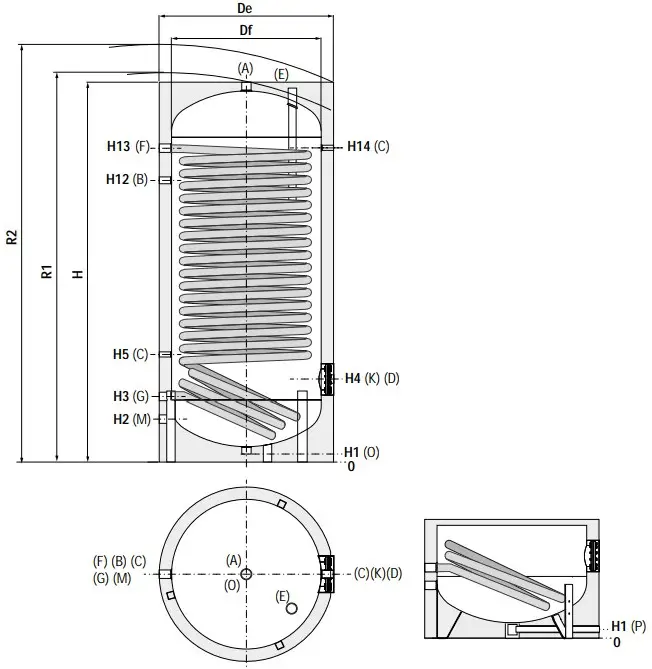
| A | Domestic hot water outlet |
| B | Recirculation |
| C | Connection for instrumentation 1/2″ G F |
| D | Connection for electric immersion heater |
| E | Connection for magnesium anode 1″1/4 G F |
| F | Primary circuit inlet 1″1/4 G F |
| G | Primary circuit outlet 1″1/4 G F |
| K | Flange for inspection |
| M | Domestic cold water circuit inlet |
| O | Drain 1″1/4 G F- for models <800 |
| P | Drain 3/4″ G F – for models >500 |
BOLLY® 1 XL WB +XL WB CLASS A (HARD FOAM INSULATION)
| [lt] | [Kg] | [mm] | Connections F | |||||||
| 200 188,8 | 96 | // 1440 550 1560 71 215 285 325 | 405 | 1055 | 1190 | 1190 | Øi120/Øe180 | 3/4″ 3/4″ 1″1/4 | 1″1/2 | |
| 300 290,5 | 130 | // 1500 650 1650 71 241 321 381 | 431 | 1091 | 1211 | 1211 | Øi120/Øe180 | 1″ 1″ 1″1/4 | 1″1/2 | |
| 400 422 | 154 | // 1780 700 1930 71 256 336 396 | 446 | 1316 | 1471 | 1471 | Øi120/Øe180 | 1″ 1″ 1″1/4 | 1″1/2 | |
| 500 497,4 | 174 | // 1800 750 1960 71 266 346 411 | 466 | 1326 | 1486 | 1486 | Øi120/Øe180 | 1″ 1″ 1″1/4 | 1″1/2 | |
| 800 789,4 | 264 | 750 2170 900 2360 101 338 418 483 | 538 | 1548 | 1808 | 1808 | Øi170/Øe240 | 1″ 1″ 1″1/4 | 2″ | |
| 1000 | 1037,9 | 303 | 850 2230 1000 2460 89 359 439 499 | 559 | 1584 | 1829 | 1829 | Øi170/Øe240 | 1″1/4 1″ 1″1/2 | 2″ |
| [lt] | [Kg] | [mm] | Connections F | |||||||||||||||||
| 800 | 789,4 | 226 | 750 | 2190 | 950 | 2330 | 2400 | 101 | 338 | 418 | 483 | 538 | 1548 | 1808 | 1808 | Øi170/Øe240 | 1″ | 1″ | 1″1/4 | 2″ |
| 1000 | 1037,9 | 255 | 850 | 2250 | 1050 | 2420 | 2500 | 89 | 359 | 439 | 499 | 559 | 1584 | 1829 | 1829 | Øi170/Øe240 | 1″1/4 | 1″ | 1″1/2 | 2″ |
Technical Data
Data have been calculated on following basis:
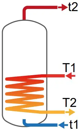
- Primary circuit at T1 and proper energy source;
- Production of DHW in continuous from 10 °C to t2;
- DHW that can be taken in the fi rst 10’ and in the fi rst hour from storage at 60°C, input 10°C and output 45°C;
- Sanitary water according to UNI CTI 8065.
| Model | Primary Flow rate | Ignition time (minutes) from 10 °C to t2 and primary at T1 | Maximum power exchange (kW) with primary at T1, secondary within 10-45 °C and constant use of DHW production | DHW continuous production lt/h within 10-45 °C and primary at T1 | |||||||||
| [m3/h] | T1/t2 | T1 | T1 | ||||||||||
| 55/50 | 65/60 | 70/60 | 80/60 | 55 | 65 | 70 | 80 | 55 | 65 | 70 | 80 | ||
| 200 | 2,5 | 40 | 42 | 30 | 20 | 21 | 31 | 36 | 47 | 522 | 773 | 899 | 1153 |
| 1,25 | 49 | 52 | 36 | 24 | 19 | 28 | 32 | 40 | 468 | 677 | 780 | 990 | |
| 300 | 3 | 44 | 46 | 32 | 22 | 30 | 45 | 52 | 66 | 751 | 1104 | 1281 | 1640 |
| 1,5 | 55 | 57 | 41 | 27 | 27 | 39 | 44 | 56 | 664 | 951 | 1093 | 1377 | |
| 400 | 3,5 | 47 | 49 | 35 | 23 | 42 | 61 | 71 | 90 | 1033 | 1510 | 1747 | 2229 |
| 1,75 | 59 | 62 | 44 | 30 | 37 | 53 | 60 | 75 | 915 | 1298 | 1486 | 1863 | |
| 500 | 3,5 | 49 | 51 | 36 | 24 | 48 | 70 | 81 | 103 | 1198 | 1740 | 2009 | 2551 |
| 1,75 | 62 | 65 | 47 | 31 | 43 | 60 | 68 | 85 | 1060 | 1487 | 1696 | 2114 | |
| 800 | 5 | 59 | 61 | 43 | 29 | 64 | 93 | 107 | 136 | 1571 | 2291 | 2650 | 3372 |
| 2,5 | 72 | 76 | 55 | 37 | 57 | 80 | 92 | 115 | 1412 | 1993 | 2277 | 2845 | |
| 1000 | 8 | 65 | 68 | 48 | 32 | 72 | 106 | 124 | 158 | 1780 | 2632 | 3058 | 3925 |
| 4 | 76 | 80 | 57 | 38 | 66 | 95 | 110 | 139 | 1642 | 2364 | 2720 | 3436 | |
| Model | Primary Flow rate | DHW produced in the first 10 minutes in lt/10’ input 10 °C output 45 °C, storage at t2 and primary at T1 | DHW produced in the first hour in lt/60’ input 10 °C output 45 °C, storage at t2 and primary at T1 | Heat exchanger pressure drop | |||||||
| [m3/h] | T1/t2 | T1/t2 | [mm.c.a.] | [mbar] | |||||||
| 55/50 | 65/60 | 70/60 | 80/60 | 55/50 | 65/60 | 70/60 | 80/60 | ||||
| 200 | 2,5 | 221 | 399 | 420 | 462 | 241 | 888 | 989 | 1193 | 1062,3 | 104,2 |
| 1,25 | 221 | 383 | 400 | 435 | 238 | 811 | 894 | 1062 | 309,7 | 30,4 | |
| 300 | 3 | 340 | 600 | 629 | 689 | 368 | 1299 | 1441 | 1728 | 830,2 | 81,4 |
| 1,5 | 339 | 574 | 598 | 645 | 363 | 1176 | 1290 | 1517 | 243,2 | 23,8 | |
| 400 | 3,5 | 492 | 855 | 894 | 974 | 531 | 1811 | 2001 | 2386 | 1263,9 | 123,9 |
| 1,75 | 491 | 819 | 850 | 913 | 524 | 1641 | 1791 | 2093 | 370,8 | 36,4 | |
| 500 | 3,5 | 581 | 1001 | 1046 | 1137 | 625 | 2103 | 2319 | 2752 | 1263,9 | 123,9 |
| 1,75 | 579 | 959 | 994 | 1064 | 617 | 1901 | 2068 | 2403 | 370,8 | 36,4 | |
| 800 | 5 | 918 | 1510 | 1570 | 1691 | 977 | 2962 | 3249 | 3826 | 2976,1 | 291,9 |
| 2,5 | 916 | 1461 | 1508 | 1603 | 967 | 2723 | 2950 | 3405 | 874,7 | 85,8 | |
| 1000 | 8 | 1203 | 1920 | 1991 | 2136 | 1270 | 3587 | 3928 | 4621 | 7358,7 | 721,6 |
| 4 | 1201 | 1875 | 1935 | 2054 | 1261 | 3372 | 3657 | 4230 | 2161,9 | 212,0 | |
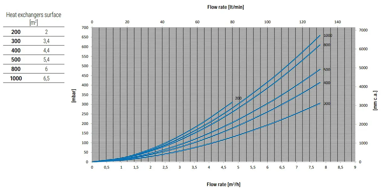
Heat Exchanger Pressure Drop
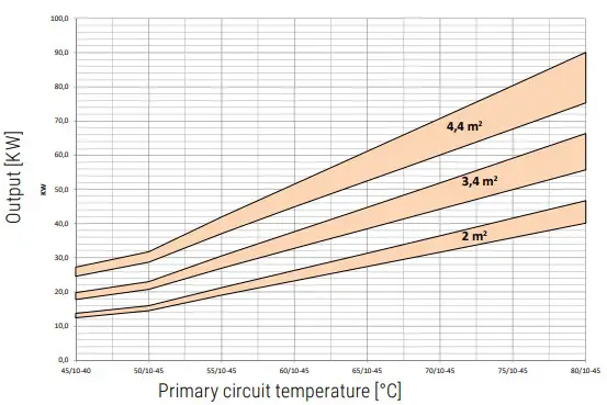
Heat Exchanger output referreD TO TEMPERAture and flow rate of primary circuit and with secondary at 10/45°C at maximum withdrawal of producible DHW (Upper limit of the curves referred to maximum primary flow rate in the heat exchanger, while the lower limit in the curves refer to the minimum primary flow rate)
| Heat exchanger surface | 2 m2 | 3,4 m2 | 4,4 m2 | |||
| Flow rate [m3/h] | MAX | MIN | MAX | MIN | MAX | MIN |
| 2,5 | 1,25 | 3 | 1,5 | 3,5 | 1,75 | |
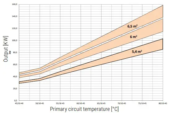
| Heat exchanger surface | 5,4 m2 | 6 m2 | 6,5 m2 | |||
| Flow rate [m3/h] | MAX | MIN | MAX | MIN | MAX | MIN |
| 3,5 | 1,75 | 5 | 2,5 | 8 | 4 | |
EXAMPLE OF INSTALLATION WITH BOLLY® 1 XL
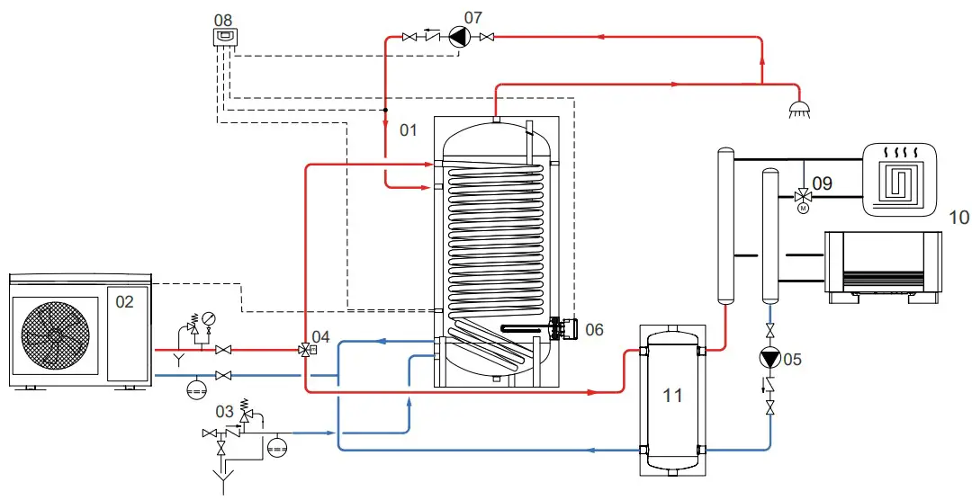
- BOLLY® 1 XL
- Generator (Heat pump)
- Hydraulic safety group
- Motorized three-way valve
- Circulation group for heating/cooling system
- Electric immersion heater (optional)
- DHW recirculation
- Electronic control /thermostat
- Thermostatic mixing valve
- Heating units
- Buffer tank
The following schemes are purely illustrative. To realize the installation, always refer to a qualified technician.
![]()


