![]() Instruction Manual
Instruction Manual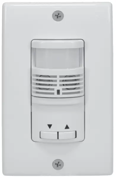 IOS-DOV-DTD-WH Dual Technology
0-10 V Dimming Occupancy Sensor
IOS-DOV-DTD-WH Dual Technology 0-10 V Dimming Occupancy Sensor
![]() WARNING
WARNING
Risk of Fire or Electric Shock
- Turn OFF power at circuit breaker or fuse and test that the power is OFF before wiring.
- To be installed and/or used in accordance with appropriate electrical codes and regulations.
- If you are not sure about any part of these instructions, consult a qualified electrician.
- Use this device only with copper or copper clad wire.
- INDOOR USE ONLY
OVERVIEW
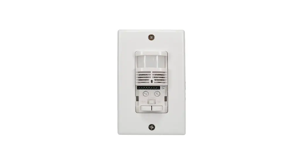
Intermatic’s IOS-DOV-DTD-WH dual technology 0-10 V dimming occupancy sensor can turn lights ON and OFF based on occupancy and allow the user to increase or decrease the lighting level. It combines the benefits of passive infrared (PIR) and ultrasonic occupancy detection technologies.
SPECIFICATIONS
| Input Voltage | 120-277 VAC, 50/60 Hz |
| Electronic Ballast | 600 VA, 120 VAC; 1385 W, 277 VAC |
| Tungsten | 1000 W, 120 VAC; 1385 W, 277 VAC |
| Standard Ballast | 660 VA, 120 VAC; 1100 VA, 220 VAC; 1520 VA, 277 VAC |
| Class 2 Dimming Output | 0-10 VDC, 120 mA maximum current sink |
| General Use | 12 A, 120-277 VAC |
| Resistive | 10 A, 125/250/277 VAC |
| Motor | 1/6 HP, 120/240 VAC |
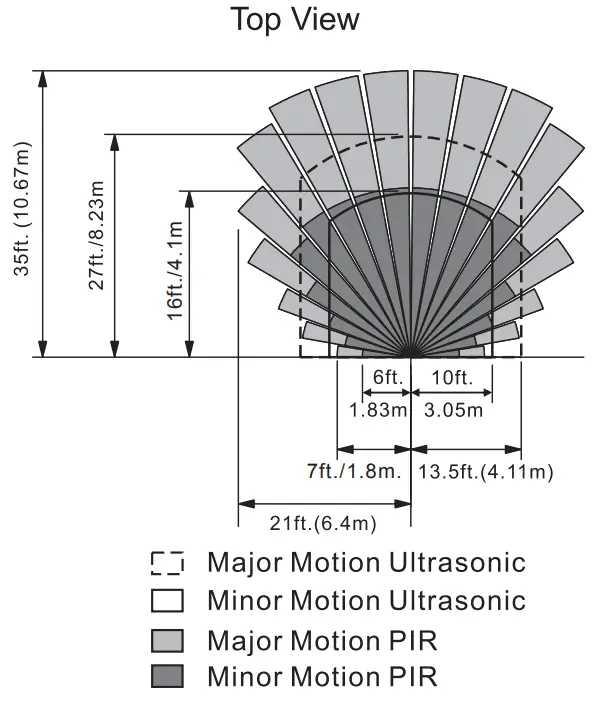
| Coverage | • PIR: up to 35 ft. (10.67 m) • Ultrasonic: up to 27 ft. (8.23 m) |
 LED Indicators
- Red LED Blinking: PIR sensor detects motion
- Green LED Blinking: Ultrasonic detects motion
Manual Up / Down Buttons:
- To turn ON the light, press the up arrow when the light is OFF. To turn OFF the light, press the down arrow when the light is ON.
- To adjust the light level, Press and hold the up arrow to increase light level and release at desired light level. Press and hold the down arrow to decrease light level and release at desired light level.
INSTALLATION
- Always switch OFF the Electrical power before installing the sensor and make sure the sensor ratings are appropriate for the luminaire being controlled.
- Wire the sensor according to the wiring diagram. (Refer To Diagram 1)
- Attach sensor to junction box with 2 screws. (Refer To Diagram 2)
- Attach Panel cover and wall plate. (Refer To Diagram 2)
Diagram 1 – Wiring Diagram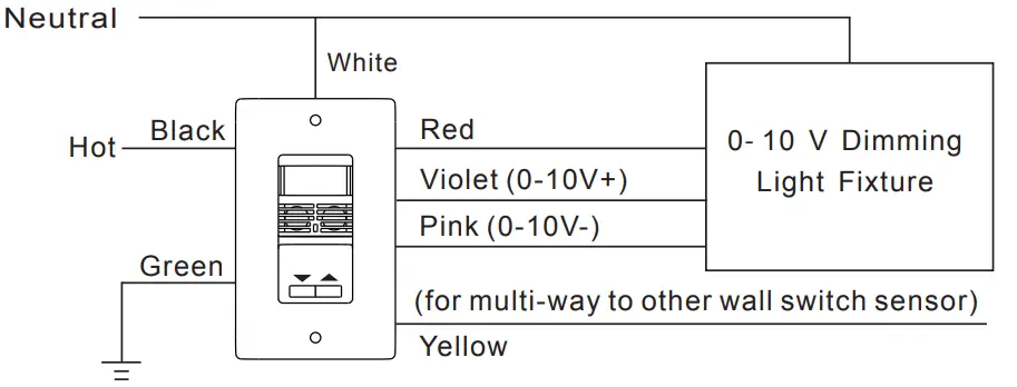 Diagram 2 – Installation
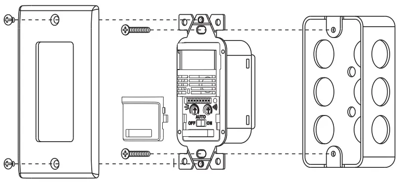 Diagram 3 – Traveler Wiring Diagram
*Note: Ground wire is REQUIRED for Multi-Way Wiring.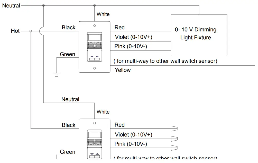
DIP SWITCH PROGRAMMING
Time Delay
Time Delay: The time delay setting assigns the duration for the lighting to stay ON after no movement is detected. The time delay is controlled by DIP switches 1 through 3. Refer to the following table to set the time delay.
| Time Delay | DIP1 | DIP2 | DIP3 |
| 30 sec | Off | Off | Off |
| 2 min | On | Off | Off |
| 4 min | Off | On | Off |
| 8 min | On | On | Off |
| 10 min | Off | Off | On |
| 15 min – Default | On | Off | On |
| 20 min | Off | On | On |
| 30 min | On | On | On |
Occupancy and Vacancy Mode Selection (DIP 4)
Use DIP 4 to select Occupancy or Vacancy mode
| DIP Switch | Mode |
| ON | Occupancy (Auto On) |
| OFF | Vacancy (Manual On) |
Dimmer Synchronization (DIP 5)
The DIP 5 controls the Dimmer Synchronization mode when the multi-way function (Diagram 3) is used. If you turn DIP 5 ON, the second sensor can turn the light fixture ON/OFF and control the dimming light level. If you turn DIP 5 OFF, the second sensor can only turn the light ON/OFF. (If using one sensor, leave the setting in the ON position)
Walk-Through Mode (DIP 6)
Turn DIP 6 ON to enable “walk through mode”. In this mode, the load will be turned ON for 2 minutes when motion is detected. If no motion is detected after 90 seconds, the load will be turned OFF 30 seconds later. If a motion is detected after 90 seconds, the load will refer to the Time delay setting.
Ambient Light Level (DIP 7)
To set the ambient light level, turn ON DIP 7 and wait for 30 seconds for the light level to calculate the current ambient light in the room. Once programmed, If there is greater ambient light than the setting the light will not turn on. If there is less ambient light than the setting the light will activate.
Ultrasonic Enable/ Disable (DIP 8)
Turn DIP 8 ON to enable Ultrasonic Technology. Turn DIP 8 OFF to disable Ultrasonic Technology.
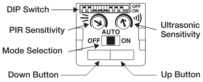
PIR/ULTRASONIC SENSITIVITY AND MODE SELECTION
 Ultrasonic Sensitivity
Turn the variable resistor to adjust the ultrasonic sensitivity. It can be adjusted from 20%
to 100%.
PIR Sensitivity
Turn the variable resistor to adjust PIR sensitivity. It can be set from 60% to 100%.
Mode Selection
The mode selection switch is used to select ON, Auto or OFF mode
- ON: Lights Always ON
- Auto: Detection determines when the lights turn ON and OFF (Occupancy or Vacancy mode)
- OFF: Lights Always OFF
LIGHT LEVEL PROGRAMMING
High- Trim, Low-Trim and Initial On Light Level Activation Programming
Before setting the 3 light levels, you must enter the set/program mode. Put the mode selection switch to the OFF position and press the UP and Down button together. The sensor is in set/program mode when there is a solid Red LED illuminated. To pick whichsetting you would like to change click the up-arrow button until you see the Red LED blink in accordance to which setting you would like to change. (1 Blink – High-Trim, 2 Blinks – Low-Trim, 3 Blinks – Initial On Level)
A. High-Trim Setting:
When the Red LED flashes one time per period, press the “up” and “down” button together to start to set the High-Trim level. Click the up arrow the number of times in accordance with the chart below for your desired setting. Once complete press the “up” and “down” button’s together to save. If complete with all programming needs return sensor to auto mode.
| Low End Trim | Number of clicks on Down Arrow |
| 80% | 1- |
| 90% | 2- |
| 100% | 3- |
B. Low-Trim Setting:
When the Red LED flashes two times per period, press the “up” and “down” button together to start to set to the Low-Trim level. Click the down arrow the number of times in accordance with the chart below for your desired setting. Once complete press the “up” and “down” button’s together to save. If complete with all programming needs return sensor to auto mode.
| Low End Trim | Number of clicks on Down Arrow |
| 10% | 1- |
| 20% | 2- |
| 30% | 3- |
C. Initial On Activation Light Level Setting:
When the Red LED flashes three times per period, press the “up” and “down” button together to start set the Initial On Activation Light level. Click the up arrow the number of times in accordance with the chart below for your desired setting. Once complete press the “up” and “down” button’s together to save. If complete with all programming needs return sensor to auto mode.
| Initial On Activation Level | Number of clicks on Up Arrow |
| 10% | 1- |
| 20% | 2- |
| 30% | 3- |
| 40% | 4- |
| 50% | 5- |
| 60% | 6- |
| 70% | 7- |
| 80% | 8- |
| 90% | 9- |
| 100% | 10- |
NOTE: You cannot program the initial on activation light level setting below the selected Low-Trim or above the selected High-Trim. (Example: High-Trim is set at 90%. Initial On Activation cannot be higher than 90%, Low-Trim is set at 30%, Initial On Activation cannot be below 30%) (If error, LED will blink constant red)
D. Factory/Default Reset:
If you want to reset the sensor to factory settings, put the mode switch to the “ON” position and press the “Up” and “Down” arrows together and hold. The Red LED will flash 2 times and the sensor will reset to the factory/default settings. The factory/default settings are as follows: (High-Trim: 100%, Low-Trim: 10%, Initial On: 50%)
5-YEAR LIMITED WARRANTY
Warranty service is available by either (a) returning the product to the dealer from whom the unit was purchased or (b) completing a warranty claim online at www.intermatic.com.
This warranty is made by: Intermatic Incorporated, Customer Service 1950 Innovation Way, Suite 300, Libertyville, IL 60048. For warranty service go to: www.Intermatic.com or call 815-675-7000.
INTERMATIC INCORPORATED
1950 Innovation Way, Suite 300
Libertyville, Illinois 60048
www.intermatic.com
158–02530


