laia TP1 All in One HD Video Conference Terminal
Copyright statement
The copyright of all the contents of this manual belongs to the company and shall not be copied, copied, copied or translated in any way without permission of the company. This manual does not contain any form of warranty, position statement or other hints. The product specifications and information mentioned in this manual are for reference only, and the contents will be updated at any time without prior notice.
Warning
This is A class A product which may cause radio interference in the living environment. In this case, users may be required to take practical measures against interference.
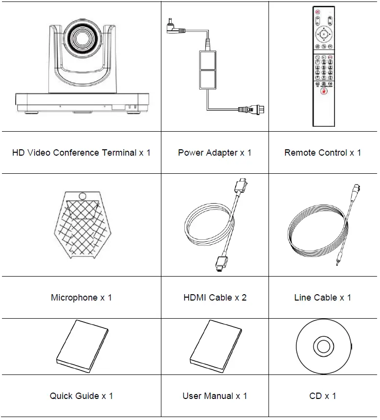
Packing List
When unpacking, please check and confirm all attachments that should be provided.
Product Introduction
The integrated HD video conference terminal adopts embedded system design, supports 1080P HD codec and h. 323, SIP communication protocol. Integrated design, convenient installation, network connection, microphone, television, plug in the power to communicate. Communicate voice and image information to each other to complete various meeting functions such as document sharing. Save meeting time and money, improve work efficiency, and create convenience for enterprises to realize face-to-face video conference interaction and all-round communication.
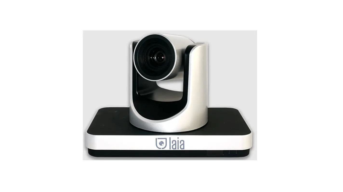
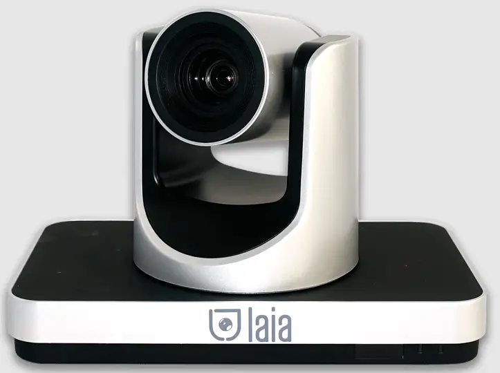
Product Appearance
Appearance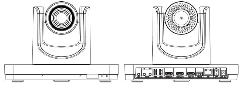
Interface
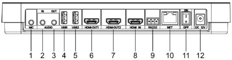
| NO | Name | Function |
| 1 | MIC | The microphone audio input interface that connects the microphone to the terminal for receiving voice |
| 2 | AUDIO IN | 3.5mm audio input interface for connecting computer, mobile phone and other sound input sources. |
| 3 | AUDIO OUT | 3.5mm audio output interface, connect the speaker box and terminal through the audio cable, and output the sound |
| 4 | USB1 | USB interface 1, used for external USB devices such as USB disk, mouse, keyboard, microphone or speakers. |
| 5 | USB2 | USB interface 2, for external USB devices such as USB disk, mouse, keyboard, microphone or speakers. |
| 6 | HDMI OUT1 | HDMI output interface 1 connects the terminal and HDTV through HDMI cable. |
| 7 | HDMI OUT2 | HDMI output interface 2 connects the terminal and HDTV through HDMI cable. |
| 8 | HDMI-IN | HDMI input interface, connect terminal and camera via HDMI cable. |
|
9 |
RS232 | RS232 interface for external RS232 equipment, such as computers, cameras, etc. (this feature is not currently supported) |
| 10 | NET | NET network interface, through the network line terminal access network. |
| 11 | ON/OFF | Power on key, power on or off. |
| 12 | DC 12V | DC 12V power input interface for connecting supporting power adapter. |
Product Specifications
| Category | Project | Details of specifications |
| Electrical characteristics | Working voltage | AC 100V ~ 240V, DC 12V |
| Power consumptio n | maximum power consumption:24W | |
|
Environmental requirements | Working state | |
| The temperature | 0°C ~ 40°C | |
| Relative humidity | 10% ~ 80% | |
| The surrounding noise | less-than 46dBA SPL | |
| Off duty | ||
| The temperature | -40°C~70°C | |
| Relative humidity | 0%~95% | |
|
Physical properties | Bare machine size (length * width * height) | 240mm × 144mm × 170mm |
| The bare weight | 1.8 kg | |
Install the Attachment
The terminal can be placed directly on the desktop, fixed to the TV or hung on the wall. Figure 1 is the schematic diagram of installation on TV, and figure 2 is the diagram of installation on wall. The bracket in the figure is not included in the packing list.
Figure 1 is installed in the TV schematic
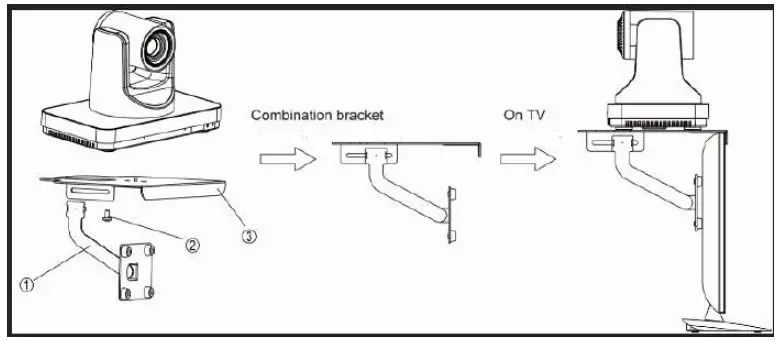
Figure 2 is installed in the wall diagram
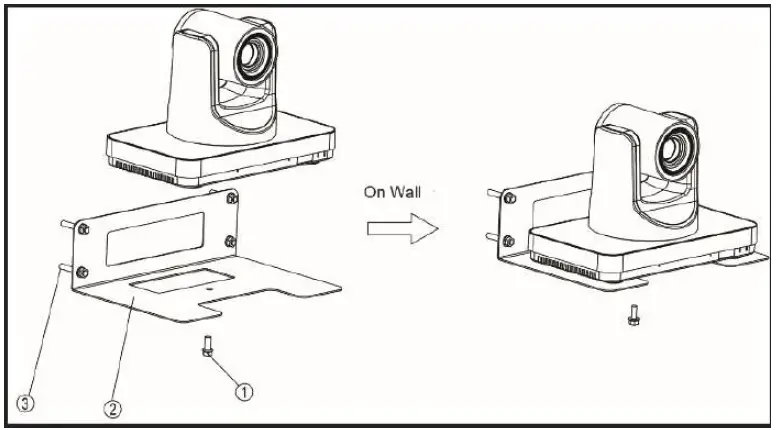
- If the terminal is placed directly on the desktop, please keep the desktop stable, pay attention to anti-skid;
- If the terminal is placed on the rack, please use screws to fix it on the rack.
- Adjust terminal orientation to avoid facing bright light sources (such as Windows). It is recommended that the terminal be facing participants.
Connection
Before connecting the cable, it is necessary to know the back interface of the terminal. The cable connection shown in the figure below contains optional configuration, for reference only. Please connect the cable according to actual needs.
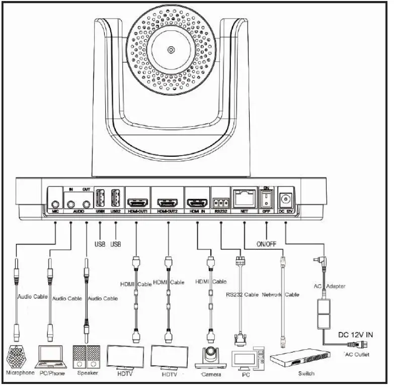
The Configuration is as follows:
- enter the video image, the external HDMI cameras connected to the terminal IN the interface.
- input voice: use a 3.5 mm audio cable to connect the supporting the microphone MIC to terminal interface.
- enter player voice: use 3.5 mm AUDIO cable, connect the player to the end of the AUDIO IN the interface.
- output the video image: use the HDMI cable HDMI connection terminal OUT1 interface to the display device interface HDMI inputs.
- output voice: use the HDMI cable HDMI connection terminal OUT1 interface to the display device of the HDMI input interface,
- Or connect the AUDIO OUT interface of the terminal to the speaker using a 3.5mm AUDIO cable.
- output in the first two video image: use the HDMI cable HDMI connection terminal OUT2 interface to the display device interface HDMI inputs.
- to connect to the Internet: using.net interface wiring terminal, the terminal access network.
- connect power: use the DC 12 v power supply cord connected to form a complete set of power adapter, and then connect the power adapter to the power socket.
Power On
Connect all equipment used in conjunction with the conference terminal before switching on the power.
Warning
- When the terminal power is on, please prevent the power cord plug from leaving the terminal and the terminal power is off.
- Please close the terminal first, then turn off the external power supply, and finally pull out the power cord. Please check whether the power cord and the power adapter are properly and reliably connected to the corresponding equipment as required below.
- Determine the ac power voltage range between 100V and 240V, and the frequency is 50Hz or 60Hz.
- The sequence definition and the corresponding voltage difference of fire line (L), zero line (N) and protection ground line (PE) must conform to international standards, and the protection ground wire must be reliably grounded.
HDMI OUT1 is used as the output interface. After connecting the cable as shown above, the power of the power adapter is connected. Press the start button (the green light is long), start the machine to display the main menu of the interface.
The indicator light of the terminal after starting up is shown in the following table:
| Indicator status | Terminal status description |
| The power indicator light is long and green | On duty |
| The power indicator is long orange | Power off but not off |
| The power indicator is off | Power off |
| The infrared receiving indicator light flashes green | Receive remote infrared signal |
Use the Remote Control
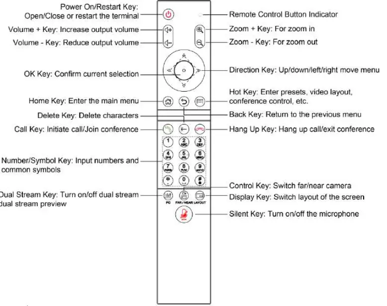
GUI Main Interface
Press the menu button of the remote control to enter the main GUI interface.
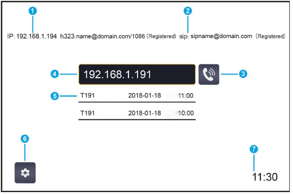
| NO | Explain | NO | Explain | NO | Explain |
| 1 | Conference terminal IP address | 2 | H323/SIP registration status | 3 | The call button |
| 4 | Remote venue IP or number input box | 5 | Address book menu | 6 | History menu |
| 7 | Diagnostic menu | 8 | Control menu | 9 | The Settings menu |
| 10 | Displays history call records | 11 | Select call protocol | 12 | Selective call rate |
When the cursor is moved to the “Settings” menu, the “address book”, “history”, “diagnosis” and “control” menu will pop up automatically. When you move the cursor to the call button, the call protocol and call rate boxes pop up automatically.
Basic Settings
Network Setting
Step 1 enter the GUI main interface and select “set > network > network Settings”.
Step 2 configures the Ethernet device parameters, as shown in the following table.
Step 3 select save to save the configuration information.
Step 4 concludes.
| Parameters of the item | parameter specification |
|
Working mode | Configure the network work mode. The options are: · automatically · 10 m full-duplex · 10 m half duplex · 100 MB full duplex · 100 m half duplex |
|
Connection type | · automatically obtain IP: terminal through the DHCP server to obtain IP address automatically.
· static IP: terminal IP address assigned by the network administrator, you need to set up the “IP address”, “subnet mask”, “default gateway and DNS address. |
| The IP address | Configure the IP address of this terminal. |
| Subnet mask | Configure the subnet mask of this terminal. |
| The default gateway | Configure the default gateway address for the IP of this terminal. |
| DNS address | Configure the IP address of the DNS server. |
| Save | Select save to save the configuration information. |
Setting of H323 Account (optional)
Set the terminal’s H323 ID and number, specify the GK address, and allow the terminal to register with GK so that it can call a meeting or other terminal through the number.
Step 1 enter the main GUI interface and select “set > account > H323 account”.
Step 2 configures the H.323 account parameter information, which is shown in the following table.
Step 3 select save to save the configuration information.
Step 4 concludes.
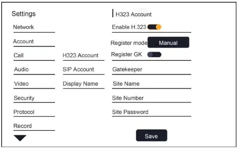
| Parameters of the item | parameter specification |
| To enable the H323. | Select whether h.323 is enabled by default. |
| Configuration mode | Select h. 323 account configuration and manually enter the information required for registration of h. 323. |
| Registered 323 H. | Enable or disable terminal registration GK server. The options are: |
| GK address | enable: terminal registered GK server.After the terminal is successfully registered to the GK server, it can pass |
| Registered name | The remote venue number calls other terminals. |
|
The terminal number | disabled: terminal not registered GK server.When a call is made using the h.323 protocol, other terminals can only be called through the IP address. |
| Password | Set the IP address or domain name of the GK server. |
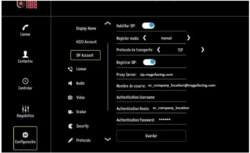
Set SIP Account (optional)
Configure the SIP parameters, set the SIP address of the terminal, and communicate with the remote through the registration number.
Step 1 enter the main GUI interface and select “set > account > SIP account”.
Step 2 configures the SIP parameters, which are described in the following table.
Step 3 select save to save the configuration information.
Step 4 concludes.
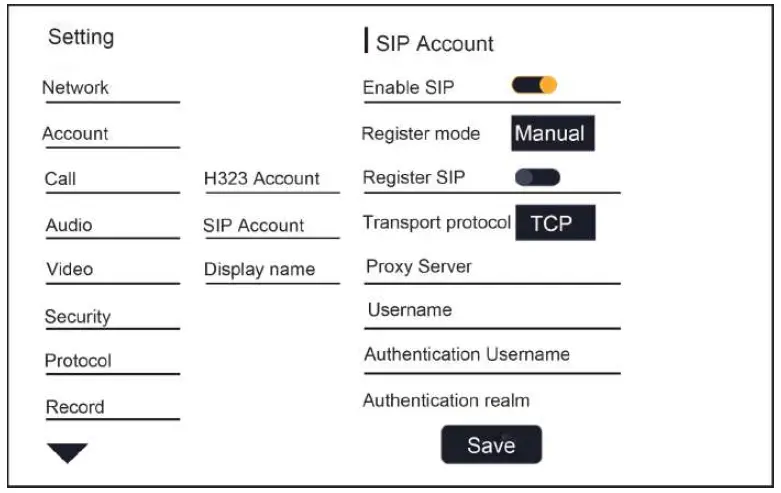
| Parameters of the item | parameter specification |
| To enable the SIP | Select whether SIP is enabled by default. |
| Configuration mode | Select the SIP account configuration and manually enter the information required for the SIP registration. |
|
SIP registration | Enable or disable terminal registration of SIP server. The options are: · enable: terminal registered SIP server.After the terminal has successfully registered to the SIP server, it can call other terminals through the remote venue number. · disabled: terminal does not register the SIP server.When calling with SIP protocol, other terminals can only be called through IP address |
| Transfer protocol | Select the transport protocol with options for TCP, UDP, TLS, and automation. |
| Proxy server | Enter the IP address or domain name of the SIP proxy server (optional). |
| The user name | This must be enabled when the user’s network environment requires that the proxy server be enabled. |
| Parameters of the item | parameter specification |
| Authenticated user name | Enter the user name (optional) used to register the SIP server. |
| Authentication domain | Enter the user name for authentication. |
| The authentication code | Enter the domain name (optional) for the |
| Save | Select the transport protocol with options for TCP, UDP, TLS, and automation. |
After the terminal registers the SIP server, you need to configure the proxy server, username, and authentication domain.
Below, you can see an example how to register one device on GoFacing platform.
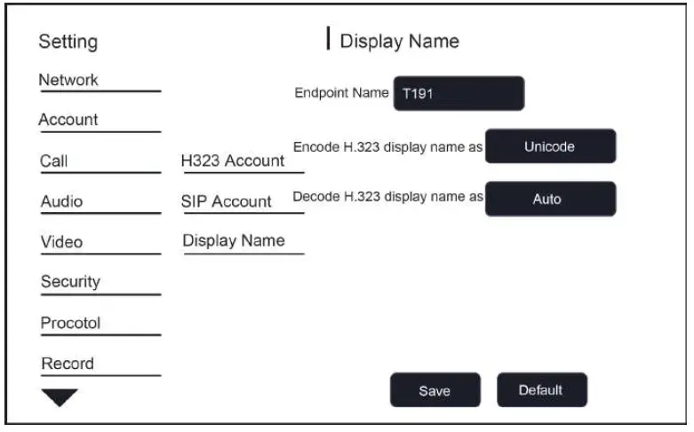
Set the Terminal Name
Step 1 enters the main GUI interface and selects “set > account > display name”.
Step 2 configures the terminal name.
Step 3 select save to save the configuration information.
Step 4 concludes.
Setting Language
Step 1: enter the GUI main interface and select “set > system > language”.
Step 2 sets the system language you need and returns.
Step 3 select save to save the configuration information.
Step 4 concludes.
Set the Date and Time
Step 1 enters the main GUI interface and selects “set > date of > system”.
Step 2 sets parameters such as date, time, and date format.
Step 3 select save to save the configuration information.
Step 4 concludes.
| Parameters of the item | parameter specification |
| Automatically gets network time | Check “get network time automatically” to indicate the time spent on the network. |
| Set the date | Set the date, do not check “automatic access network time” to take effect. |
| Set a time | Set the time, do not check “automatic access network time” to take effect. |
| The NTP service | Set up the NTP time server. |
| Select the time zone | Set the time zone in your area. |
| Parameters of the item | parameter specification |
| Enable 24-hour format | Sets whether the 24-hour format is enabled. |
| Select date format | Select the order in which the date, month, and day formats are displayed. |
Restore Factory Settings
Step 1 enter the GUI main interface and select “set > system > reset”.
Step 2 select restore factory Settings.
Step 3 select save to save the configuration information.
Step 4 concludes.
Warning
After the factory Settings are restored, all the terminal parameters you previously configured will be lost. Please be careful!


