PHYLRICH PHY1137 3-4 Medi Thermostatic Valve
GENERAL CHARACTERISTICS
WE RECOMMEND THAT ALL PLUMBING PRODUCTS BE INSTALLED BY A LICENSED PROFESSIONAL IMPORTANT: Thoroughly read instructions before installation.
WARNING: IF THIS VALVE IS INSTALLED UPSIDE-DOWN A REVERSE CARTRIDGE IS NOT AVAILABLE. CONSEQUENTLY, VALVE MUST BE REMOVED AND REINSTALLED RIGHT-SIDE UP.
- The valve is designed with two outlets for ease of installation, but are not intended to be used concurrently with each other. Using both outlets will reduce the performance of the valve.
VALVE SPECIFICATION
- Recommended supply pressure = 20 to 80 psi (1,38-5,52 bar)
- Recommended hot water supply temperature = 120° to 140°F (48°-60°C)
- Operating pressures between hot and cold supplies should vary no more than 30 psi (2,07 bar). If water pressure exceeds 70 psi (4,83 bar), install a pressure-reducing valve.
- Ensure the mixing valve is in compliance with local plumbing codes when setting the temperature on the water heater.
- It is the installer’s responsibility to verify correct temperature setting to prevent any risk of scalding prior to consumer use.
- For use with shower heads rated at 1.8 gpm (6.8 L/min) or higher

- Female 3/4” NPT inlets and outlets
- Factory temperature setting = 100°F (38°C)
- Temperature range = 52° to 118°F (11°-48°C)
- Temperature hot supply = 149° to 180°F (65°-82°C)
- Temperature cold supply = 50° to 72°F (10°-22°C)
- Temperature stability = Compliant with ASSE 1016
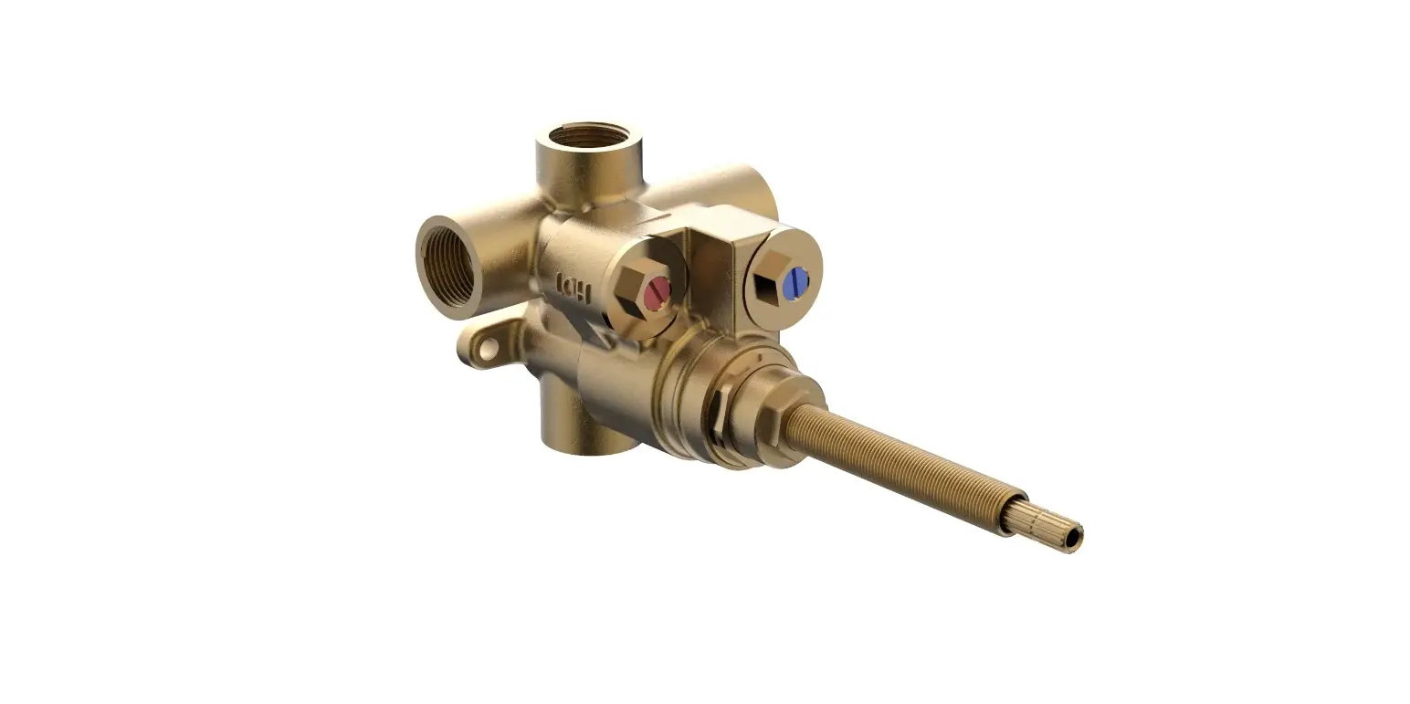
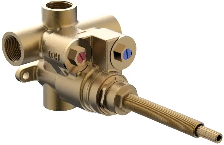
PARTS BREAKDOWN
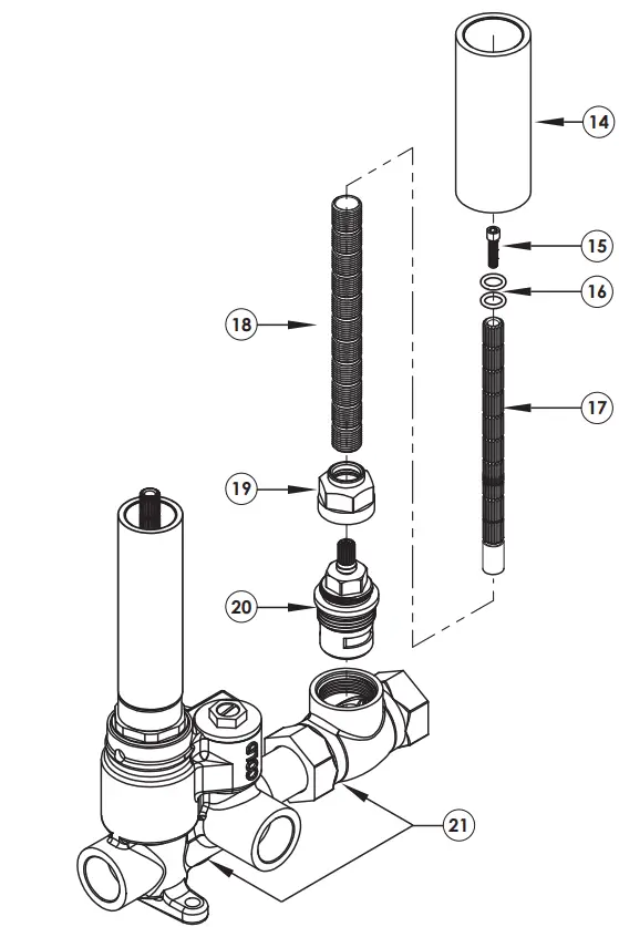
- Medi Thermostatic Valve
- TURN TO PAGE 8 FOR VALVE TURN MECHANICS

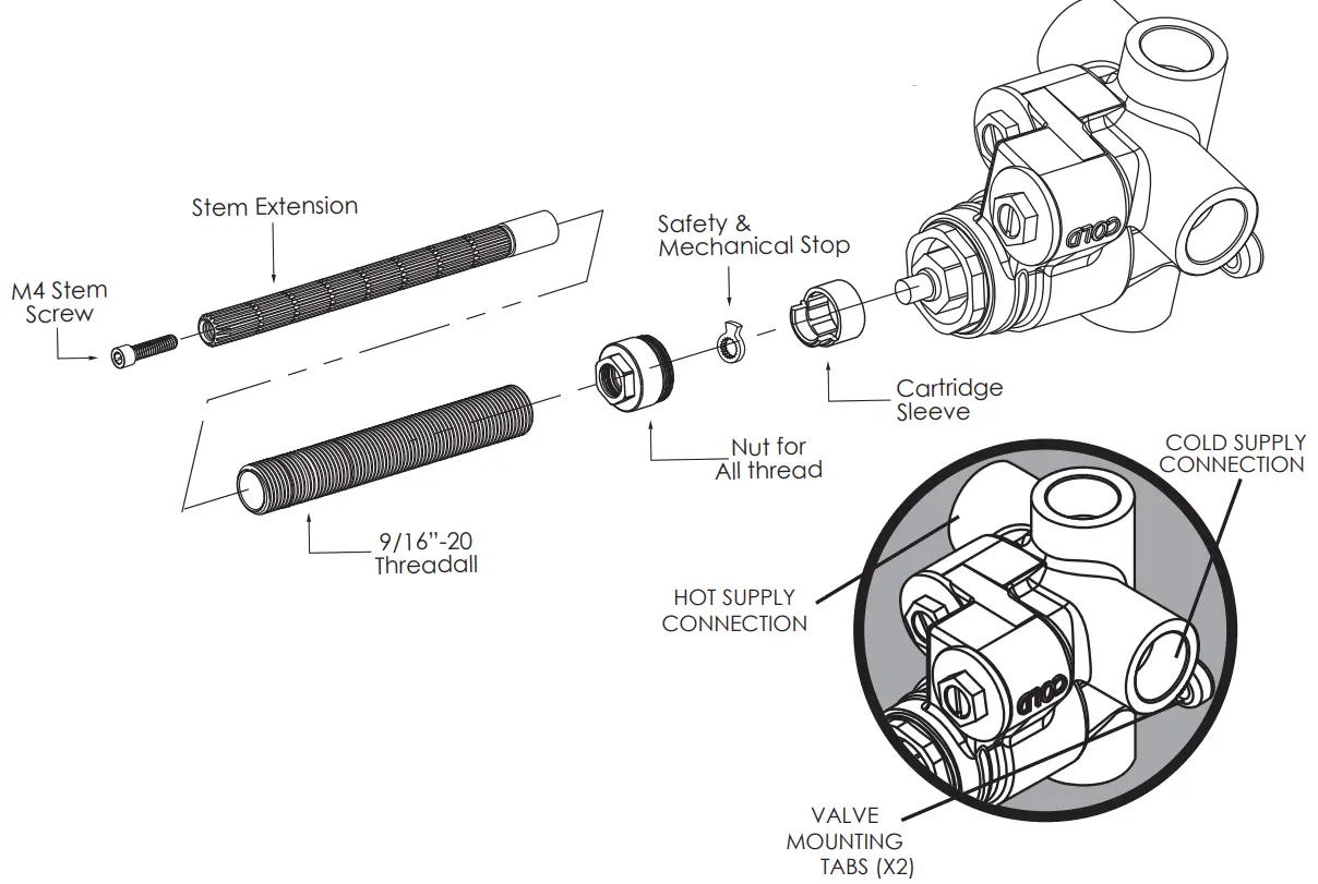
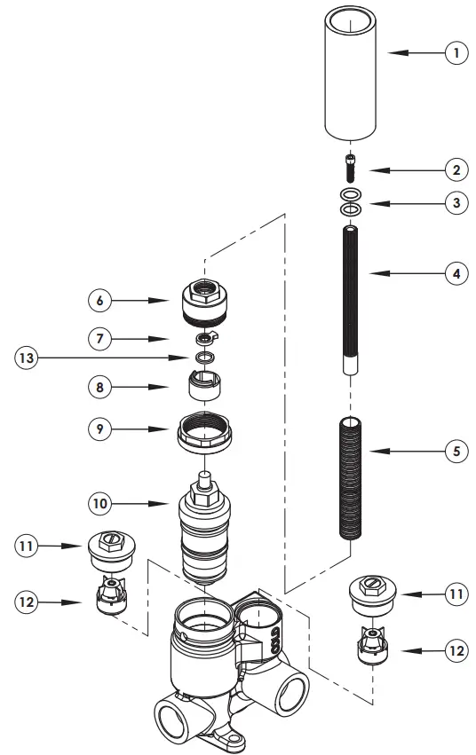
1-135 3/4” Medi Therm Valve # PART # DESCRIPTION QTY. 1 11496 MUD GUARD 1 2 92335 SCREW 1 3 90011 O-RING 2 4 10054 STEM EXTENSION 1 5 10209 SHANK,NIPPLE THREAD ALL 1 6 11610 MEDITHERM NUT FOR ALL THREAD 1 7 11320 SAFETY AND MECHANICAL STOP 1 8 11598 CARTRIDGE LIMIT STOP SLEEVE, MEDI 1 9 11599 RETAINER NUT 1 10 11583 CARTRIDGE 1 11 2-256 SHUT OFF NUT 2 12 11593 CHECK VALVE 2 13 92050 WASHER ACETAL 1 - Medi Thermostatic Valve w/ 3/4” VOLUME CONTROL
- 3/4” NPT female outlet

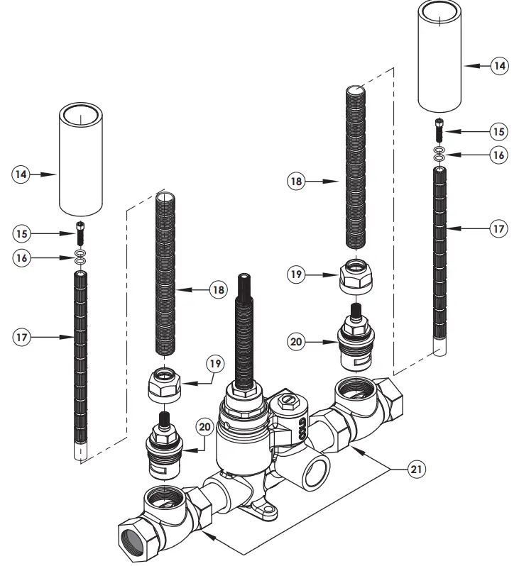
1-136 3/4” Medi Therm Valve w/ Volume Control # PART # DESCRIPTION QTY. PARTS FROM THERM VALVE 1 11496 MUDGUARD 1 2 92335 SCREW 1 3 90011 O-RING 2 4 10054 STEM EXTENSION 1 5 10209 SHANK, NIPPLE THREAD ALL 1 6 11610 MEDITHERM NUT FOR ALL THREAD 1 7 11320 SAFETY AND MECHANICAL STOP 1 8 11598 CARTRIDGE LIMIT STOP SLEEVE, MEDI 1 9 11599 RETAINER NUT 1 10 11583 CARTRIDGE 1 11 2-256 SHUT OFF NUT 2 12 11593 CHECK VALVE 2 13 92050 WASHER ACETAL 1 14 11496 MUDGUARD 1 15 92157 SCREW 1 16 90011 O-RING 2 17 11416 STEM EXTENSION 1 18 11498 SHANK, NIPPLE THREAD ALL 1 19 10058 NUT, ADAPTOR CARTRIDGE 1 20 10215 CARTRIDGE VALVE 1 21 2-259 3/4” MEDITHERM W/ VOLUME CONTROL 1 - Medi Thermostatic Valve w/ 2 VOLUME CONTROL
- 3/4” NPT female outlets

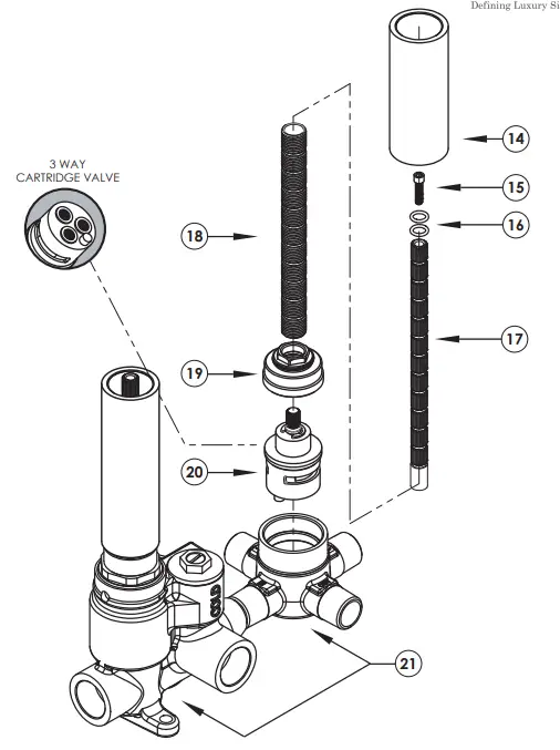
# PART # DESCRIPTION QTY. PARTS FROM THERM VALVE 1 11496 MUD GUARD 1 2 92335 SCREW 1 3 90011 O-RING 2 4 10054 STEM EXTENSION 1 5 10209 SHANK,NIPPLE THREAD ALL 1 6 11610 MEDITHERM NUT FOR ALL THREAD 1 7 11320 SAFETY AND MECHANICAL STOP 1 8 11598 CARTRIDGE LIMIT STOP SLEEVE, MEDI 1 9 11599 RETAINER NUT 1 10 11583 CARTRIDGE 1 11 2-256 SHUT OFF NUT 2 12 11593 CHECK VALVE 2 13 92050 WASHER ACETAL 1 14 11496 MUDGUARD 2 15 92157 SCREW 2 16 90011 O-RING 4 17 11416 STEM EXTENSION 2 18 11498 SHANK,NIPPLE THREAD ALL 2 19 10058 NUT, ADAPTOR CARTRIDGE 2 20 10215 CARTRIDGE VALVE 2 21 2-260 3/4” MEDITHERM W/ 2 VOLUME CONTROL 1 - Medi Thermostatic Valve w/ 3 WAY DIVERTER
- 1/2” NPT female outlets

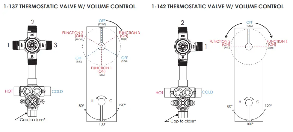
1-137 3/4” Medi Therm Valve w/ 3 Way Diverter # PART # DESCRIPTION QTY. 1 11496 MUD GUARD 1 2 92335 SCREW 1 3 90011 O-RING 2 4 10054 STEM EXTENSION 1 5 10209 SHANK,NIPPLE THREAD ALL 1 6 11610 MEDITHERM NUT FOR ALL THREAD 1 7 11320 SAFETY AND MECHANICAL STOP 1 8 11598 CARTRIDGE LIMIT STOP SLEEVE, MEDI 1 9 11599 RETAINER NUT 1 10 11583 CARTRIDGE 1 11 2-256 SHUT OFF NUT 2 12 11593 CHECK VALVE 2 13 92050 WASHER ACETAL 1 14 11496 MUD GUARD 1 15 92157 SCREW 1 16 90011 O-RING 2 17 11416 STEM EXTENSION 1 18 11498 SHANK,NIPPLE THREAD ALL 1 19 10349 NUT, 3 WAY DIVERTER 1 20 11297 CARTRIDGE VALVE, 3 WAY 1 21 2-261 3/4” MEDITHERM W/ 3 WAY DIVERTER 1 - Medi Thermostatic Valve w/ 2 WAY DIVERTER
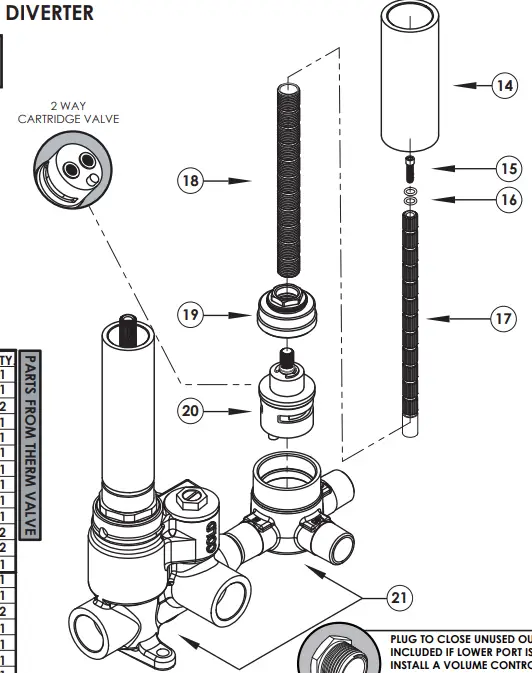
- 1/2” NPT female outlets

1-142 3/4” Medi Therm Valve w/ 2 Way Diverter # PART # DESCRIPTION QTY. PARTS FROM THERM VALVE 1 11496 MUD GUARD 1 2 92335 SCREW 1 3 90011 O-RING 2 4 10054 STEM EXTENSION 1 5 10209 SHANK,NIPPLE THREAD ALL 1 6 11610 MEDITHERM NUT FOR ALL THREAD 1 7 11320 SAFETY AND MECHANICAL STOP 1 8 11598 CARTRIDGE LIMIT STOP SLEEVE, MEDI 1 9 11599 RETAINER NUT 1 10 11583 CARTRIDGE 1 11 2-256 SHUT OFF NUT 2 12 11593 CHECK VALVE 2 13 92050 WASHER ACETAL 1 14 11496 MUD GUARD 1 15 92157 SCREW 1 16 90011 O-RING 2 17 11416 STEM EXTENSION 1 18 11498 SHANK,NIPPLE THREAD ALL 1 19 10349 NUT, 3 WAY DIVERTER 1 20 11567 CARTRIDGE VALVE, 2 WAY 1 21 2-262 3/4” MEDITHERM W/ 2 WAY DIVERTER 1
ROUGH IN DIMENSIONS / ROUGH IN VALVE TO FRAME
(All dimesions shown are to the nearest 1/16”) Once the desired location has been determined, install a cross support beam to wall studs. Ensure to level the valve & secure to the cross support. The valve should be level horizontally, vertically, & parallel to finished wall.
- 3”x 8” Opening for finished wall for 2 valves 3” x 13” for 3 valves


Pre-assemble fittings before attaching to cross support. Attach the “COLD” Inlet to Cold Supply & “HOT” Inlet to Hot Supply using copper supply lines.
IMPORTANT: Thoroughly flush supply lines to remove any debris prior to installation to pevent damage & malfunction of thermostatic cartridge.
- Use plumber’s tape or thread sealant to all threaded port joints & attach to valve. All soldering/brazing of fittings shall be performed a minimum of 6” away from valve.

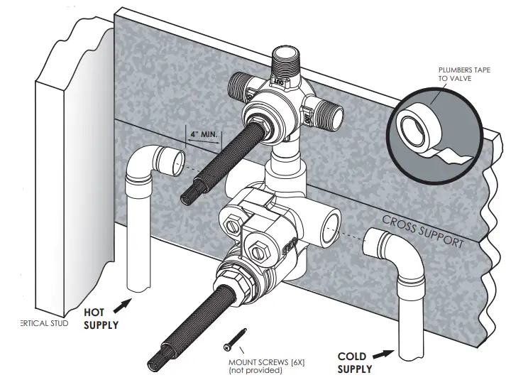
WARNING: DO NOT APPLY HEAT DIRECTLY TO THE VALVE AS THIS MAY DAMAGE RUBBER & PLASTIC SEALS & WILL AVOID WARRANTY. TURN ON WATER SUPPLIES TO VALVE & CHECK FOR LEAKS.
MAINTENANCE
THERMOSTATIC CARTRIDGE
Carefully remove the trim and plate and place in a safe location for the time being. Use a flat head screwdriver to shut off the water supply to the cartridge by turning the temporary shutoff screws clockwise until screw stops. Ensure to close both the hot and cold sides of the water supplies. Remove extensions to gain access to the cartridge nut. Unscrew the cartridge nut using a 11/16” socket wrench or adjustable wrench, if possible.
Gently pull the cartridge out of the housing body (rotating cartridge while pulling may assist in removing). Clean the cartridge by rinsing it under running water to remove any possible debris. Wipe cartridge and housing seat clean and apply a thin film of NON-PETROLEUM GREASE to o-rings.
NOTE: Do NOT use oil based lubricants as this may cause the o-rings to dry out over time and crack.
How to calibrate temperature:
To limit the amount of HOT water allowed to mix with cold water, use a 4 “ long flat blade screw driver to remove the stem. Unscrew and remove nut for all thread using a 3/4” socket. Remove the limit safety stop and rotate the stem counterclockwise till the desired maximum temperature is found. The maximum temperature is factory set at 120°F. Once the desired temperature is set, reinstall the safety stop at the maximum position. Proceed installing the stem and trim.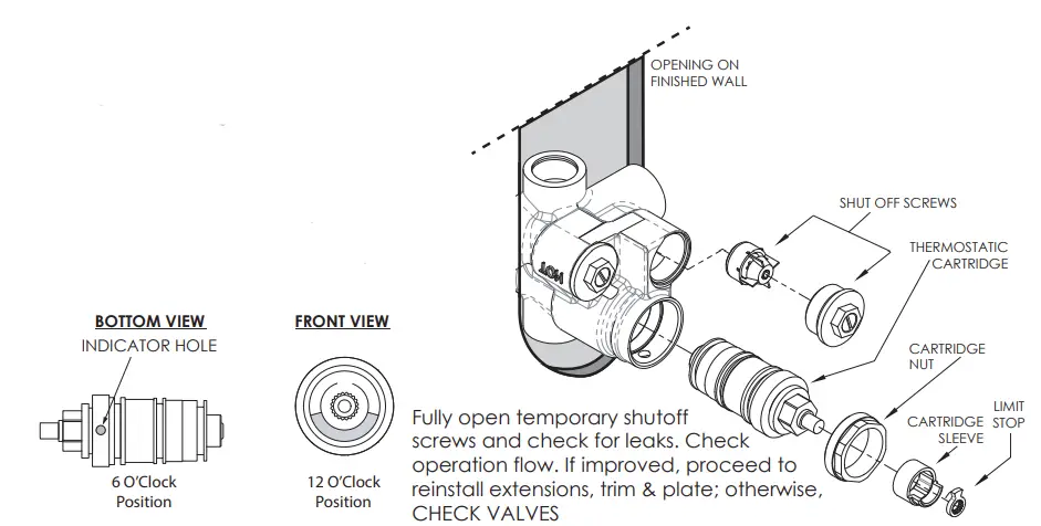
Carefully install the cartridge back into the housing body and tighten nut to 10 ft-lbs (13,56 nm).
ATTENTION: Ensure the INDICATOR HOLE on cartridge is orientated at the 6 O’Clock position. The Temp erature stop must be in the 12 O’Clock position.
CHECK VALVES
Shut off water supply at main or upstream from valve body. Remove check valve nut with a 15 mm socket wrench from the body. If check valve needs replacement, forcefully remove check valve w/ needle nose pliers. Wipe check valve and housing seat clean and apply a thin film of NON-PETROLEUM GREASE to o-rings. Install new check valves by pressing them in evenly & ensuring check valve snaps into place.
NOTE: Do NOT use oil based lubricants as this may cause o-rings to dry out over time and crack.
Tighten check valves to 10 ft-lbs (13,56 nm).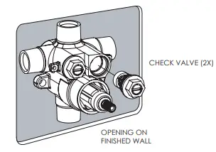
Reinstate water supply from upstream and check for leaks.
Check operation of flow. If improved, proceed to reinstall extensions, trim, & plate; otherwise, see PARTS BREAKOUT for any replacement parts needed.
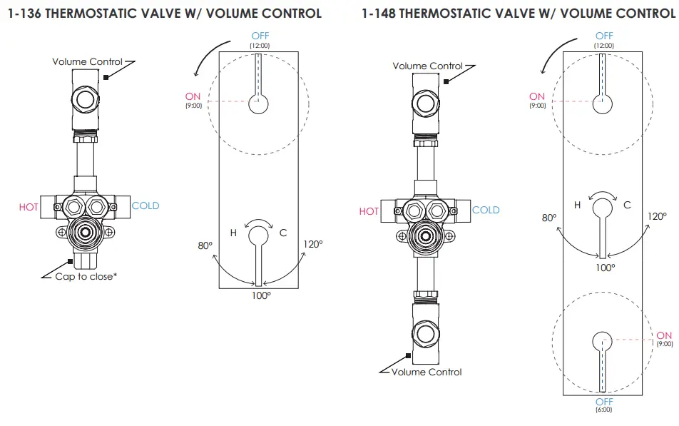
VALVE TURN MECHANICS
1261 Logan Ave., Costa Mesa, CA 92626 P:714.361.4830 F: 714.617.3120 www.phylrich.com


 Dan_lc-13 Manual")


