![]() Neurostimulator
Neurostimulator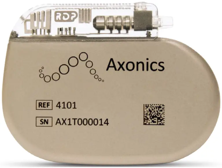 Implant Manual
Recharge-Free | Model 4101
LABEL SYMBOLS
This section explains the symbols found on the product and packaging.
| SYMBOL | DESCRIPTION |
 | Axonics Neurostimulator |
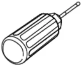 | Axonics Torque Wrench |
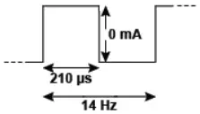 | Neurostimulator default waveform with 14 Hz frequency, 0 mA amplitude and 210 µs pulse width |
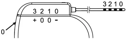 | Neurostimulator default electrode configuration: Electrode 0: negative (-) Electrode 1: Off (0) Electrode 2: Off (0) Electrode 3: Positive (+) Case: Off (0) |
| Product Serial Number | |
| Manufacturer | |
| Product Model Number | |
| Manufacturing Date | |
 | Non-ionizing electromagnetic radiation |
| Refer to instructions for use available electronically | |
| Temperature limitation | |
 | Humidity limitation |
 | Pressure limitation |
| Do not reuse | |
 | Sterilized using Ethylene oxide |
| Use by | |
 | Do not use if package is damaged |
 | Do not re-sterilize |
 | Open here |
| For USA audiences only Caution: U.S. Federal law restricts this device for sale by or on the order of a physician | |
 | Warning / Caution |
 | Product Literature |
 | Magnetic Resonance (MR) Conditional |
| IC | Industry Canada certification number |
 | This device complies with all applicable Australian Communications and Media Authority (ACMA) regulatory arrangements and electrical equipment safety requirements |
| FCC ID | US Federal Communications Commission device identification |
 | This device is packaged in two sterile barriers |
 | The Neurostimulator is connected to the Axonics Tined Lead Model 1201 (also included in Model 2201) |
INTRODUCTION
This manual provides information about the Axonics Sacral Neuromodulation (SNM) System Neurostimulator (Model 4101), which is a part of the Axonics SNM System. The Neurostimulator is connected to the Axonics Tined Lead (Model 1201 or 2201).
INDICATIONS, WARNINGS, AND PRECAUTIONS
- Refer to Indications for Use insert for indications and contraindications.
- Refer to Information for Prescribers booklet for warnings, precautions, adverse events, patient selection and clinical summary.
- Refer to MRI guidelines for information on MRI compatibility and requirements.
DEVICE DESCRIPTION
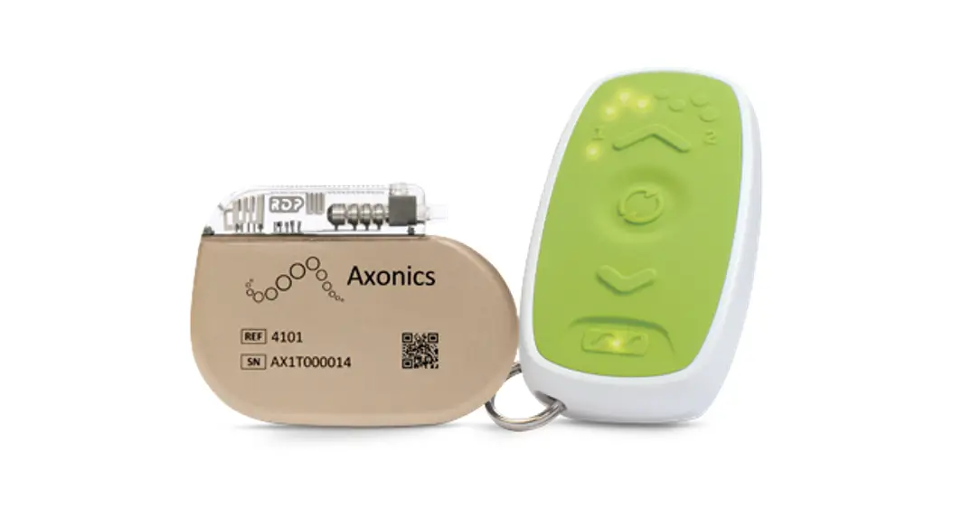
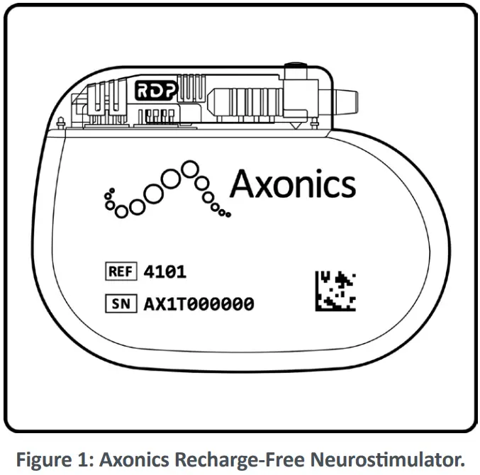
The Axonics Recharge-Free Neurostimulator (Figure 1) is part of the Axonics SNM System. The Neurostimulator is a programmable device that is connected to the Axonics Tined Lead, which conducts stimulation pulses to the sacral nerve.
Package Contents
The Neurostimulator package contains the following:
- Neurostimulator
- Torque wrench
- System registration form
- Patient identification card
- Product Insert with Indications for Use
The contents of the inner package are STERILE.
The contents of the Neurostimulator package are intended for single use only.
System Registration Form and Patient Identification Card
The system registration form registers the device and creates a record of the device in Axonics’ implant data system. The patient identification card is also packaged with this device. The patient should carry the identification card at all times.
STORAGE AND USAGE ENVIRONMENT
Component Packaging
Any component that has been compromised in any way should not be implanted; this includes the re-use of non-reusable product. Do not implant the component if any of the following have occurred:
- The storage package or sterile pack has been damaged, pierced, or altered, as sterility cannot be guaranteed, which may lead to infection.
- The component itself shows any signs of damage. The component may not function properly.
- The use-by date has expired. In this case, component sterility cannot be guaranteed, and infection may occur.
- The sterile component was dropped onto a non-sterile surface. In this case, the sterility cannot be guaranteed, and infection may occur.
Usage Environment:
The following lists the appropriate temperature, humidity, and pressure usage conditions for use of the Neurostimulator:
- Temperature: 20 °C to 45 °C
- Pressure: The Neurostimulator should function at up to 30 m (100 feet) underwater (403 kPa) and at altitudes up to 3000 m (10,000 feet) associated with activities like hiking and skydiving (as low as 70 kPa)
Shipping and Storage Environment:
The following lists the appropriate temperature, humidity, and pressure conditions for shipping and storing the Neurostimulator:
- Temperature (short term: 3 days): -10ºC to 55ºC
- Humidity (short term: 3 days): 15% to 95%
- Pressure (short term): 57 kPa to 106 kPa
If the Neurostimulator is exposed to extreme temperatures, it may be permanently damaged and should not be used, even if it has returned to a temperature that is within the specified operating range.
Sterilization
The contents of this package have been sterilized using ethylene oxide. This device is for single use only and should not be re-sterilized.
SPECIFICATIONS
Table 1 shows the Neurostimulator physical specifications. For detailed descriptions and specifications for other components and accessories, refer to the product literature for those devices.
Table 1: Neurostimulator Specifications.
| Physical Attributes | Height | 39 mm |
| Length | 53 mm | |
| Thickness | 6.7 mm | |
| Weight | 24.5 g | |
| Volume | 10 cc | |
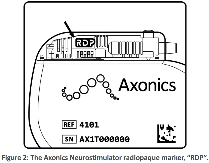
| Radiopaque identifier | RDP | |
| Stimulation Characteristics | Frequency | 2 – 50 Hz |
| Pulse Width | 60 – 330 µs | |
| Amplitude | 0 – 8 mA | |
| Minimum Amplitude Step Size | 0.05 mA | |
| Ramping | 0 – 30 s | |
| Stimulation Mode | Continuous or Cycling | |
| Mode of Operation | Current-Controlled |
Note: All dimensions are approximate.
Table 2 shows the expected life of the Neurostimulator, estimated at typical stimulation settings:
Bipolar Lead Configuration, Frequency 14 Hz, Pulse Width 210 µs, continuous stimulation, impedance = 1200 Ω.
Table 2: Neurostimulator Expected Usable Life.
| Stimulation Amplitude | 0.5 mA | 1.3 mA | 2.0 mA | 3.0 mA |
| Life (Years) | 22 | 15 | 9 | 5 |
Note: The neurostimulator battery may last longer than 22 years at lower energy use settings.
Table 3 shows the materials used in the Neurostimulator kit components that come in contact with human tissue.
Table 3: Human-Contact Materials.
| Device | Component | Material |
| Neurostimulator | Neurostimulator case | Titanium |
| Neurostimulator header | Epoxy | |
| Septum and strain relief | Silicone | |
| Setscrew | Titanium | |
| Adhesive | Silicone | |
| Torque wrench | Torque wrench handle | Polyetherimide |
| Torque wrench shaft | Stainless steel |
Note: The Neurostimulator case, which contains the electronics and power source, is hermetically sealed.
X-RAY IDENTIFICATION
The radiopaque marker allows physicians to identify the manufacturer and model number under standard x-ray procedures. For the Axonics Neurostimulator, the designated code is RDP, which appears as light characters on a black background (Figure 2).
NEUROSTIMULATOR IMPLANT PROCEDURE
The following section describes the procedure for implanting the Axonics Neurostimulator. This procedure should be performed when an Axonics tined lead has already been implanted.
Procedure Supplies
In addition to the general surgical tools required by the physician, the following supplies are needed for the preparation, implantation, programming, and Remote Control pairing of the Neurostimulator:
- Axonics Neurostimulator
- Axonics Clinician Programmer (CP)
- Axonics Remote Control
![]() Caution
Caution
The user should avoid damaging the Neurostimulator and be especially cautious using sharp instruments as damage to the Neurostimulator may require a surgical replacement.
Neurostimulator Preparation
Before opening the sterile Neurostimulator package, the Clinician Programmer (CP) should be used to communicate with the Neurostimulator to verify the ability to communicate and confirm the battery status of the Neurostimulator. Refer to the CP Manual for further instructions.
Creating the Neurostimulator Pocket
- The Neurostimulator will be placed in a subcutaneous pocket at the anterior surface of the muscle in the upper buttock area. Create a small incision, approximately 4 cm in length which is slightly longer than the smaller dimension of the Neurostimulator, and then bluntly dissect a subcutaneous pocket.
Notes:
• The Neurostimulator should be placed no deeper than 3.0 cm (about 1 in) below the skin and should be parallel to the skin. If the Neurostimulator is too deep, programming the device may be unsuccessful.
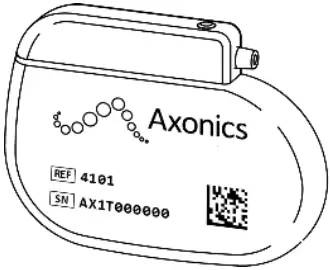
• The Neurostimulator should be implanted horizontally (Figure 3), preferably with the lead coming in laterally to avoid kinking of the lead. If the lead is not long enough to accommodate a lateral insertion, placing the lead insertion medially is acceptable.
• For a patient with another neurostimulator already implanted, the neurostimulators should be placed as far away as practical and separated by a minimum of 20 cm (8 in).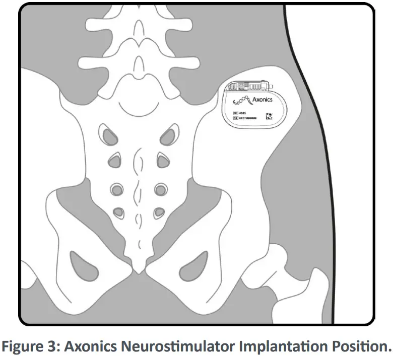 Caution
• The Neurostimulator implant site should be irrigated with sterile saline or water, and it is recommended that IV antibiotics be administered perioperatively. Do not soak the Neurostimulator in antibiotic solution as this may affect lead connections.
• The Neurostimulator has been sterilized. The Neurostimulator should not be placed on any non-sterile surface. The Neurostimulator should not be placed on skin. An infection may require surgical removal of the implanted system. - Use the tunneling tool to create a tunnel from the lead incision site to the neurostimulator pocket. Refer to the Tined Lead Manual for detailed tunneling and lead implant instructions.
Connecting the Lead to the Neurostimulator
- The components should be wiped and dried to remove any fluids before making the connections. If necessary, use sterile water or a non-ionic antibiotic solution, then wipe dry. Caution
Failure to completely dry the components could lead to undesired stimulation, intermittent stimulation, or loss of therapy. - Ensure that the Neurostimulator connector block is dry and clean.
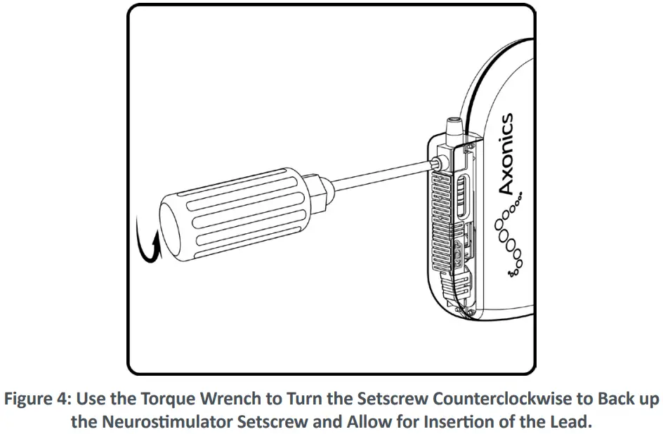
- Use the torque wrench to turn the setscrew counterclockwise to back up the setscrew. (Figure 4)
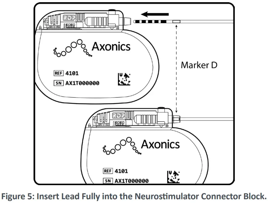
- Insert the lead into the Neurostimulator connector block until fully seated and the lead cannot be inserted further. Marker D on the lead should be inside the Neurostimulator strain relief (Figure 5). The retention sleeve on the tined lead should be positioned under the Neurostimulator setscrew.
 Caution
• Avoid pulling the lead body taut when implanted.
• Do not attempt to insert the lead into the Neurostimulator if the setscrew is not sufficiently retracted as doing so may cause damage to the lead and/or cause the lead to not seat fully into the connector block.
• Ensure that the setscrew tightens on the retention sleeve, not an electrode. Tightening the setscrew onto the contact could damage the contact, leading to lack of therapy. - Fully insert the torque wrench into the hole of the Neurostimulator connector block. Tighten the setscrew by turning the torque wrench clockwise until it clicks (Figure 6).
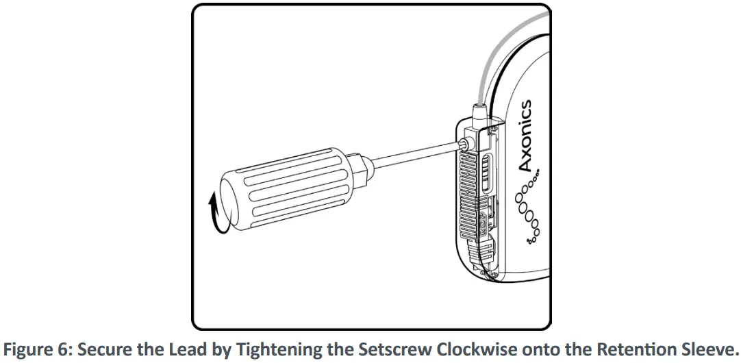 Caution
• Ensure that the torque wrench is fully inserted into the setscrew. Otherwise, the setscrew may be damaged, which can result in intermittent or loss of stimulation.
• The torque wrench is designed for single use only and cannot be assured to work appropriately if used for multiple surgeries. Discard the torque wrench after use.
Implanting the Neurostimulator
- Place the Neurostimulator into the subcutaneous pocket. The etched writing can face either towards or away from the skin incision. Ensure that the lead curves gently away from the Neurostimulator with no sharp bends.
Note: The Neurostimulator should be placed no deeper than 3.0 cm (about 1 in) below the skin and should be parallel to the skin. If the Neurostimulator is too deep, telemetry may be unsuccessful. Caution
Do not coil excess length in front of Neurostimulator. Wrap excess length around the perimeter of the Neurostimulator (Figure 7) or place under the Neurostimulator to minimize interference with telemetry during programming.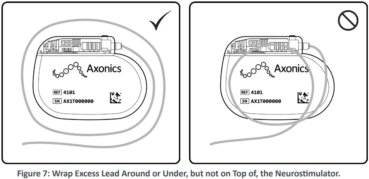
- Use the Clinician Programmer to check the impedances and ensure good function and connectivity of the system.
Notes:
• The Neurostimulator should be in the subcutaneous pocket during system interrogation to ensure proper readings.
• Refer to the Clinician Programming Manual for detailed instruction on checking the system integrity and impedances.
Completing the Implant Procedure
- Close and dress all incisions.
- Any opened or used products which are no longer sterile should be discarded appropriately. It is recommended to recycle non-biohazardous waste to the extent possible.
- Program the patient’s Neurostimulator and Remote Control. Refer to the Clinician Programming Manual for more detailed instruction.
- Give a Remote Control and patient ID card to the patient.
Caution
The patient should carry the Remote Control at all times to be able to adjust or turn off the Neurostimulator. - Complete the system registration paperwork and return to Axonics.
- Schedule the patient’s follow-up visits at regular intervals to ensure that the stimulation is programmed optimally.
Post-Surgery Management
Patients should be monitored post implant. Administer prophylactic antibiotics for 24 hours.
Patients should avoid sudden movements and putting pressure on implant site. This will reduce risk of movement or migration of the implanted system.
Replacing the Neurostimulator
Removal of the Neurostimulator is recommended at the end of useful life, which will vary depending on individual stimulation parameters.
- Carefully open the implant site and remove the Neurostimulator from the subcutaneous pocket. Avoid cutting the tined lead to preserve for connection with the new Neurostimulator.
- Clean the Neurostimulator connector block and lead with sterile water. Wipe both dry with sterile gauze.
- Use the torque wrench to loosen the setscrew in the Neurostimulator connector block by turning it counterclockwise (Figure 5).
- Gently remove the lead from the Neurostimulator.
Caution
Replace any device that shows signs of damage, pitting, or corrosion. - Set aside the explanted components.
- Connect the lead and replacement Neurostimulator according to the steps above.
Dispose of explanted devices as bio-hazardous waste.
WIRELESS COMMUNICATION
Model: 4101
FCC ID: 2AEEGT
IC: 20225-T
FCC Compliance
This device complies with part 15 of the FCC Rules. Operation is subject to the following two conditions:
- This device may not cause harmful interference, and
- This device must accept any interference received, including interference that may cause undesired operation
This transmitter is authorized by rule under the Medical Device Radio communication Service (in part 95 of the FCC Rules) and must not cause harmful interference to stations operating in the 400.150–406.000 MHz band in the Meteorological Aids (i.e., transmitters and receivers used to communicate weather data), the Meteorological Satellite, or the Earth Exploration Satellite Services and must accept interference that may be caused by such stations, including interference that may cause undesired operation.
This transmitter shall be used only in accordance with the FCC Rules governing the Medical Device Radio Communication Service. Analog and digital voice communications are prohibited. Although this transmitter has been approved by the Federal Communications Commission, there is no guarantee that it will not receive interference or that any particular transmission from this transmitter will be free from interference.
IC Compliance
This device complies with Industry Canada license-exempt RSS standard(s). Operation is subject to the following two conditions: (1) this device may not cause interference, and (2) this device must accept any interference, including interference that may cause undesired operation of this device.
FCC and IC Compliance
This device may not interfere with stations operating in the 400.150–406.000 MHz band in the Meteorological Aids, Meteorological Satellite, and Earth Exploration Satellite Services and must accept any interference received, including interference that may cause undesired operation.
Note: Changes and modifications to the Neurostimulator are not authorized by Axonics could void FCC and IC certification and negate the user’s authority to use the product.
Quality of Wireless Service
This device operates in the 402-405 MHz frequency and the maximum effective radiated power of the Neurostimulator communication is below the limit of 25 µW ERP/EIRP as specified in EU: EN ETSI 301-839 and USA: FCC 47 CFR Part 95; Subpart I. The Remote Control or Clinician Programmer must be within 1 meter from the implant for successful communication.
Wireless Security
The Neurostimulator can only communicate with a single Remote Control that is paired to it using the Clinician Programmer. Any Axonics Clinician Programmer can communicate with a Neurostimulator. Additional mechanisms exist to ensure the integrity of radio data.
CUSTOMER SERVICE
For questions regarding the Axonics SNM System, call our
Customer Support Center toll-free at +1-877-929-6642.
Additional information and product manuals can be found at our website: www.axonics.com
![]() Axonics® and Axonics Sacral Neuromodulation System® are trademarks of Axonics, Inc., registered or pending registration in the U.S. and other countries.
Axonics® and Axonics Sacral Neuromodulation System® are trademarks of Axonics, Inc., registered or pending registration in the U.S. and other countries.
![]() Axonics, Inc.
Axonics, Inc.
26 Technology Drive
Irvine, CA 92618 (USA)
www.axonics.com
Tel. +1-(877) 929-6642
Fax +1-(949) 396-6321
![]() March, 2022
March, 2022
All Rights Reserved. Copyright 2022.
Axonics, Inc.
110-0230-001 Rev H


