![]() Series HS
Series HS
Installation and Operating Manual
Electric switch mechanisms and housings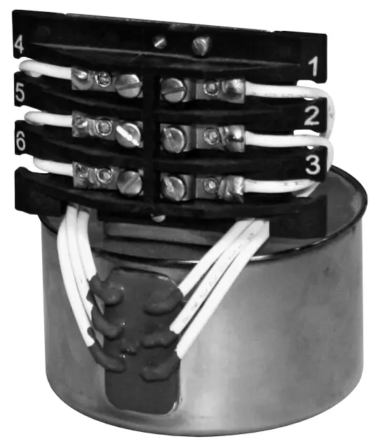

UNPACKING
Unpack the instrument carefully. Make sure all components have been removed from the foam protection. Inspect all components for damage. Report any concealed damage to the carrier within 24 hours. Check the contents of the carton/crates against the packing slip and report any discrepancies to Magnetrol. Check the nameplate model number to be sure it agrees with the packing slip and purchase order. Check and record the serial number for future reference when ordering parts.
 These units are in conformity with the provisions of: 1. Directive 2014/34/EU for equipment or protective system intended for use in potentially explosive atmospheres. EC-type examination certificate number ISSeP09ATEX024X (Ex d units).
PRINCIPLE OF OPERATION
Figures 1 & 2 illustrate the simple, reliable operating principle of a float level switch. Switching action is obtained through the use of a magnetic sleeve (4) and a float (3), displacer or flow sensing element and a switching mechanism (2). These two basic component assemblies are separated by a non-magnetic, pressure tight enclosing tube (5). The switch (2) and magnet (1) are assembled to a mechanism with a swinging arm which operates on precision stainless steel pivots. As level of a liquid in a vessel rises (Figure 1), the float rides on the liquid surface moving the magnetic sleeve upward in the enclosing tube and into the field of the switch mechanism magnet. As a result, the magnet is drawn in tightly to the enclosing tube moving the switch adjusting screw and allowing the activating arm of the snap switch to move, making or breaking the electrical circuit. As the liquid level recedes (Figure 2), the float and magnetic sleeve moves downward until the switch magnet releases and is drawn outward, away from the enclosing tube by a tension spring. This in turn allows the activating arm of the snap switch to move, thus reversing switch action. Switch mechanisms may include a single switch or multiple switches, depending on operational requirements and switching action desired.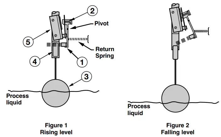
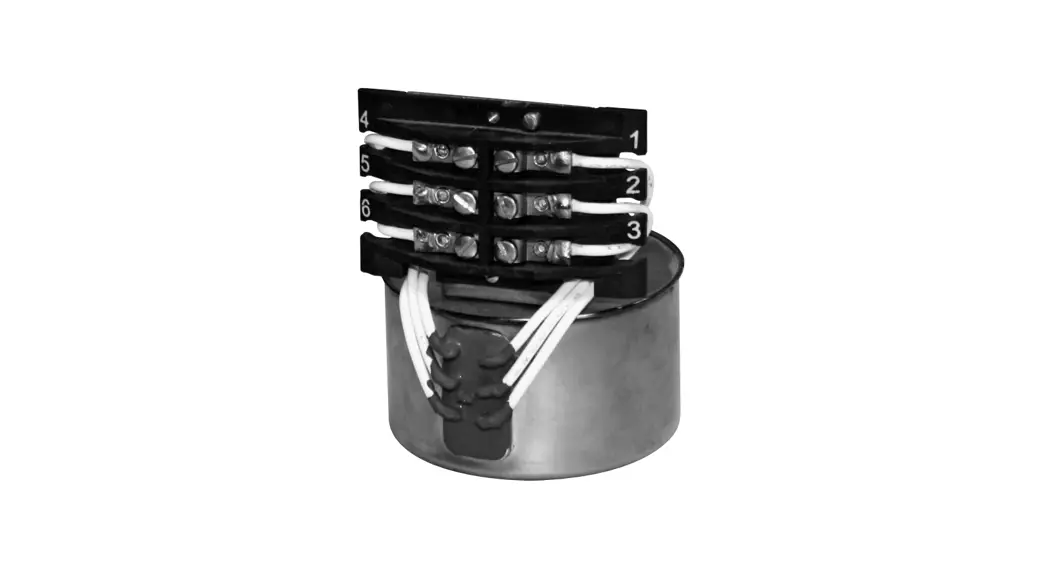
DESCRIPTION
Magnetrol mechanical level controls are available with snap-action micro switches, hermetically sealed in a positively pressurized capsule for extended switch mechanism and contact life.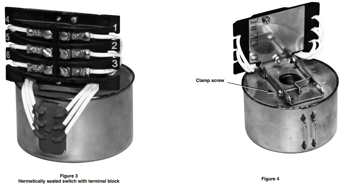
MOUNTING
Replacing the complete switch mechanisms
CAUTION: Before attempting to remove a switch mechanism, be certain to pull disconnect switch or otherwise assure that electrical circuit through control is de-energized.
- Remove the switch housing cover (see page 6 and up).
- Disconnect wiring from supply side of terminal block on switch mechanism. Note and record lead wire terminal locations.
- Loosen clamp screw in mounting clamp until mechanism slides freely on enclosing tube, refer to Figure 4
- Slide switch mechanism off of enclosing tube. If mechanism is to be reused, ensure that it is placed on a clean surface, free of metallic particles that may be attracted to the switch magnet.
- Loosen mounting screw so that switch frame will fit over e-tube. Install switch mechanism by sliding it over the enclosing tube. Slide mechanism down until the bottom of the frame and terminal block are resting on the switch spacer or washer. The switch spacer or washer should be resting on the hub of the housing base.
- Tighten the mechanism clamp screw so that the mechanism is firmly clamped to the enclosing tube.
- Reattached supply-side wiring to the terminal block. 8. Reinstall the switch housing cover (see page 6 and up).
- Reconnect power supply and test switch action under operating conditions.
WIRING
Circuits shown are for direct-acting level switches and are reversed in side mounting float-in-tank models, which utilize a reversing float pivot.
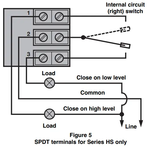
SPDT terminal connections
- Rising level closes contacts 1 & 2, see Figure 5.
- Falling level closes contacts 2 & 3.
- Wiring Diagram is reversed (high level actuation becomes low level actuation, etc.) when this switch mechanism is used on side mounted float switches employing a reversing pivot (Models B40, T52, T62, T63, T64, etc.).
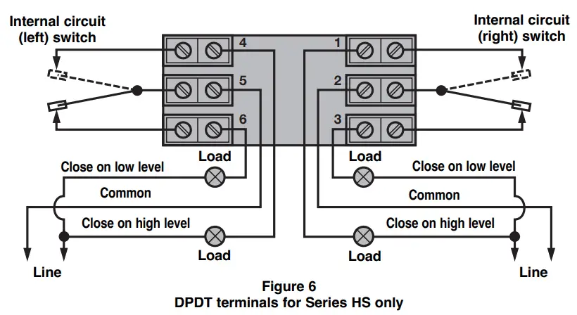
DPDT terminal connections
- Rising level closes contacts 4 & 5 and 1 & 2, see Figure 6.
- Falling level closes contacts 5 & 6 and 2 & 3.
- Double pole action is obtained by simultaneous operation of the right and left side single pole double throw switches.
- Wiring diagram is reversed (close on high becomes close on low, etc.) when this switch mechanism is used on side mounted float switches employing a reversing pivot. (Models B40, T52, T62, T63, T64 etc.)
PREVENTIVE MAINTENANCE
Inspect switch mechanisms, terminals and connections regularly. Proof test interval to be determined by application requirements (required reliability, operating conditions, site requirements, etc).
Inspect switch mechanisms, terminals and connections
- DO NOT operate your control with defective or maladjusted switch mechanisms.
- Level controls may sometimes be exposed to excessive heat or moisture. Under such conditions, insulation on electrical wiring may become brittle, eventually breaking or peeling away. The resulting “bare” wires can cause short circuits.
NOTE: Check wiring carefully and replace at the first sign of brittle insulation. - Vibration may sometimes cause terminal screws to loosen. Check all terminal connections to be certain that screws are tight.
NOTE: Spare switches should be kept on hand at all times.
SWITCHES
Switch ratings
| SWITCH SERIES | SWITCH TYPE | Process① Temperature range °C (°F) | LOAD | RATING | |||||
| Volts AC | Volts DC | ||||||||
| 120 | 240 | 480 | 24 | 120 | 240 | ||||
| HS | Hermetic (Silver contacts) | -45 to +290⑤ (-50 to 550) | Non-Inductive Amp | 5.0 | 5.0 | – | 5.0 | 0.5 | 0.25 |
| Inductive Amp | – | – | – | 3.00 | – | – | |||
REPLACEMENT SWITCH MECHANISMS
Any model numbers preceded with an “X” are specially modified controls. Contact the factory for replacement part numbers.
Partn°:
Digit in partn°: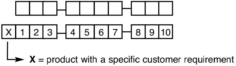
Serial n°: 
See nameplate, always provide complete partn° and serial n° when ordering spares.
EXPEDITE SHIP PLAN (ESP)
Several parts are available for quick shipment, within max. 1 week after factory receipt of purchase order, through the Expedite Ship Plan (ESP).
Parts covered by ESP service are conveniently grey coded in the selection tables.
Replacement mechanisms
| Switch Series | 8th, 9th & 10th Digit | Switch Contacts | Set points | Switch assembly |
| HS | HA9, HB3, HB4, HFC, HM2, HM3, H7A | SPDT | 1 | 089-8301-002 |
| HB7, HB8, HB9, HGC, HM6, HM7,H7C | DPDT | 1 | 089-8301-001 |
Process Temperatures are based on -40 °C to +70 °C (-40 °F to +160 °F) ambient temperatures.
On condensing applications, temperature down-rated to +200 °C (+400 °F) process at +40 °C (+ 100 °F) ambient.
REPLACEMENT SWITCH HOUSINGS
Switch housing replacement assemblies
When ordering replacement parts for an existing Magnetrol instrument, please specify:
- Model and serial numbers of control.
- Description and part number of replacement kit.
The proper replacement switch housing kit and parts can be determined by the last three characters of the model number.
Cast aluminum housings (tall)
Die cast aluminum TYPE 4X housing replacements are available for general purpose or weatherproof installations.
Explosion proof NEMA 7/9 and ATEX housing replacements are available for hazardous atmosphere locations.
Die cast aluminum housings are finished with a baked-on polyester powder coat paint.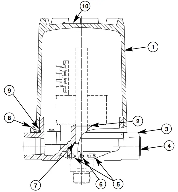
- Housing cover
- Washer
- Housing base
- Stopping plug
- Base lock screw
- Base lock screw
- Base O-ring
- Cover lock screw
- Cover O-ring
- Caution tag
Figure 7
Standard cast aluminium housing (tall)
Assemble / Disassemble instructions
- Disconnect control from power supply before opening.
- In case of ATEX Ex d approved housing, first unlock cover lock screw (8) before unscrewing the cover (1) counterclockwise. Lift housing cover straight upwards to avoid damaging the inside switch mechanism.
- Replacement of housing base (3) and/or base O-ring (7).
3.1 First remove housing cover (1) – see 1-2.
3.2 Remove entire switch mechanism (see page 3).
3.3 Remove washer (2).
3.4 Loosen base lock screws (5) & (6).
3.5 Slide housing base (3) of enclosing tube.
3.6 O-ring (7) can be accessed/replaced. - Replace part and mount in opposite order.
- Close housing cover (1) clockwise and tighten cover lock screw (8) in case of ATEX Ex d approved housing.
Replacement housing kits
Table with switch & housing model codes:
| Column header | Data |
| Switch contacts | “SPDT” or “DPDT” |
| Housing height | “Tall” |
| Housing type | Weatherproof (IP 66) | |
| Switch & housing code | e.g. H7A, HM2, H7C, HM6, … | |
| Description | Kit contains part(s) | Replacement part |
| Cover kit for tall housing | 1, 9, 10 | 089-6582-031 |
| Base kit for M20 x 1,5 cable entry | 3, 4, 5, 6, 7, 9 | 089-6582-039 |
| Base kit for 1″ NPT-F cable entry | 3, 4, 5, 6, 7, 9 | 089-6582-030 |
| Cover ‘O’-ring | 9 | 012-2201-253 |
| Base ‘O’-ring | 7 | 012-2201-116 |
| Washer | 2 | 005-7101-001 |
| Housing type | ATEX Ex d, flameproof | |
| Switch & housing code | e.g. HFC, HA9, HGC, HB9, … | |
| Description | Kit contains part(s) | Replacement part |
| Cover kit for tall housing | 1, 8, 9, 10 | 089-6582-037 |
| Base kit for M20 x 1,5 cable entry | 3, 4, 5, 6, 7, 9 | 089-6582-040 |
| Base kit for 1″ NPT-F cable entry | 3, 4, 5, 6, 7, 9 | 089-6582-041 |
| Cover ‘O’-ring | 9 | 012-2201-253 |
| Base ‘O’-ring | 7 | 012-2201-116 |
| Washer | 2 | 005-7101-001 |
| Housing type | FM NEMA 7/9, explosion proof | |
| Switch & housing code | e.g. HM3, HM7, … | |
| Description | Kit contains part(s) | Replacement part |
| Cover kit for tall housing | 1, 9, 10 | 089-6582-031 |
| Base kit for 1″ NPT-F cable entry | 3, 4, 5, 6, 7, 9 | 089-6582-030 |
| Cover ‘O’-ring | 9 | 012-2201-253 |
| Base ‘O’-ring | 7 | 012-2201-116 |
| Washer | 2 | 005-7101-001 |
REPLACEMENT SWITCH HOUSINGS
Cast iron housings
Cast iron ATEX Exd housing replacements are available for hazardous atmosphere locations. The cast iron cover and base are finished with an epoxy paint.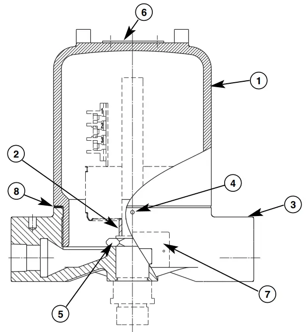
- Housing cover
- Switch spacer
- Housing base
- Cover lock screw
- Base lock nut
- Caution tag
- Nameplate
- Cover gasket
Figure 8
Standard cast iron housing
Assemble / Disassemble instructions
- Disconnect control from power supply before opening.
- First unlock cover lock screw (4) before unscrewing the cover (1) counterclockwise.
- Lift housing cover straight upwards to avoid damaging the inside switch mechanism.
- Replacement of housing base (3).
4.1 First remove housing cover (1) – see 1-3.
4.2 Remove entire switch mechanism (see page 3).
4.3 Remove switch spacer (2).
4.4 Loosen base lock nut (5) counterclockwise.
4.5 Unscrew housing base (3) counterclockwise. - Replace and mount in opposite order.
- Close housing cover (1) clockwise and tighten cover lock screw (4).
SWITCH AND HOUSING MODEL CODES
The following charts identify the switch and housing model codes used with the buoyancy products. The eighth, ninth and tenth digit combinations may be used to identify the type and number of switches, number of contacts, switch magnet strength as well as housing type, size and options.
| Weather proof (IP 66) | ATEX – IECEx (IP 66) | FM | Magnet dot color | Set points | Switch contacts | Housing height | Switch type | ||||
| II 2G Ex d IIC T6 Gb | NEMA 7/9 | ||||||||||
| Cast aluminium | Cast aluminium | Cast iron (ATEX only) | Cast alu | ||||||||
| M20x1.5 | 1″ NPT | M20x1.5 | 1″ NPT | M20x1.5 | 3/4″ NPT | 1″ NPT | |||||
| H7A | HM2 | HFC | HA9 | HB3 | HB4 | HM3 | Yellow | 1 | SPDT | Tall | HS herm. sealed dry contact |
| H7C | HM6 | HGC | HB9 | HB7 | HB8 | HM7 | Yellow | 1 | DPDT | Tall | |
IMPORTANT
SERVICE POLICY
Owners of Magnetrol products may request the return of a control; or, any part of a control for complete rebuilding or replacement. They will be rebuilt or replaced promptly. Magnetrol International will repair or replace the control, at no cost to the purchaser, (or owner) other than transportation cost if:
a. Returned within the warranty period; and,
b. The factory inspection finds the cause of the malfunction to be defective material or workmanship.
If the trouble is the result of conditions beyond our control; or, is NOT covered by the warranty, there will be charges for labour and the parts required to rebuild or replace the equipment.
In some cases, it may be expedient to ship replacement parts; or, in extreme cases a complete new control, to replace the original equipment before it is returned. If this is desired, notify the factory of both the model and serial numbers of the control to be replaced. In such cases, credit for the materials returned, will be determined on the basis of the applicability of our warranty.
No claims for misapplication, labour, direct or consequential damage will be allowed.
RETURNED MATERIAL PROCEDURE
So that we may efficiently process any materials that are returned, it is essential that a “Return Material Authorisation” (RMA) form will be obtained from the factory. It is mandatory that this form will be attached to each material returned. This form is available through Magnetrol’s local representative or by contacting the factory. Please supply the following information:
- Purchaser Name
- Description of Material
- Serial Number and Ref Number
- Desired Action
- Reason for Return
- Process details
Any unit that was used in a process must be properly cleaned in accordance with the proper health and safety standards applicable by the owner, before it is returned to the factory.
A material Safety Data Sheet (MSDS) must be attached at the outside of the transport crate or box.
All shipments returned to the factory must be by prepaid transportation. Magnetrol will not accept collect shipments.
All replacements will be shipped Ex Works.
![]() BULLETIN N°: BE 42-694.2
BULLETIN N°: BE 42-694.2
EFFECTIVE: JULY 2021
SUPERSEDES: September 2014
UNDER RESERVE OF MODIFICATIONS
European Headquarters & Manufacturing Facility
Heikensstraat 6
9240 Zele, Belgium
Tel: +32-(0)52-45.11.11
e-mail: [email protected]
www.magnetrol.com


