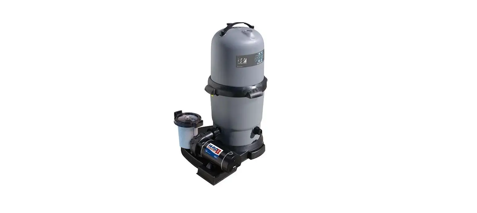
waterway 522-5147-6S ClearWater II Cartridge Filter System 
Introduction
Our ClearWater II Cartridge Filter System is shipped from Waterway complete with everything you need right in the box. Assemble filter system only after above-ground pool is installed. Fill pool with water. Do not raise water level above pool return line.
The pool equipment should be located between pool skimmer and return line. The filtration system should not be closer than 2 ft. and not further than 5 ft. from the pool. The ClearWater II Cartridge Filter System needs to be on a completely flat surface (e.g. patio block, cement slab, etc.). The pump will require a 110 volt/20 amp service.
WARNING: A GFCI is required. Follow national and local building and safety codes.
Before opening shipping carton, make sure box is in the upright position. Inside the carton, you will find:
- One base
- One pump (packaged in separate box)
- One filter
- Two lengths of 6 ft. hose
- One bag with fittings
INSTALLATION INSTRUCTIONS
WARNING! READ ALL INSTRUCTIONS AND WARNING LABELS BEFORE OPERATING FILTER!
- Place filter and base on a level, secure surface. Place the pump on the base to the left of the filter. The pump should now be facing the filter marked “Inlet”. There is no need to disassemble filter or pump assemblies.
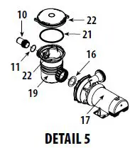
- Open pump trap lid and remove 2″ gasket. Place 2″ gasket into union nut. Hand tighten union nut to suction side of pump (Detail 5).
- Secure pump to base using the pin & anchor assemblies (Detail 4).
- Open fittings bag and remove coupling assembly (Detail 2). Assemble 2″ gasket, coupling, coupling o-ring, and 2″ union nut, and thread into inlet side of filter.
- Thread 2″ union nut to pump discharge (Detail 3). Slip o-ring over threads of hose adapter (Detail 5) and thread it into the front of the trap (Detail 1).
- From the fittings package, remove 1 1/2″ hose adapter and o-ring (Detail 2). Thread into the outlet side of the filter tank.
- Remove 4 hose clamps from the fittings bag. Select one of the hose lengths and slip one clamp over the end of hose adapter. Place the end of the hose onto the hose adapter (pump suction) and the other end to the hose adapter end of the pool skimmer. Repeat steps with filter outlet to
pool return. - Fill pool until water level is halfway up length of skimmer throat.
- Open air release knob. Plug in and turn on pump. Air will pass out of the filter through the air release knob. Once water discharges from knob, close it.
NOTE: Water may drip from air relief knob for a few minutes after closing. This is normal and will stop after the threads are empty of water.
CLEANING INSTRUCTIONS
If the pressure gauge on your filter reads 5 PSI or higher than the original starting pressure, the filter needs to be cleaned. The Aqua Star Cartridge Filter System features the exclusive 1-2-3 Safety Locking System to ensure safe and simple filter maintenance.
- Turn off pump.
WARNING: Never attempt to clean filter while pump is running. This is a pressurized vessel. It could cause severe injury or harm to your person. Plug skimmer and pool return lines or drain pool water level to below pool return line. - Slowly open the air release knob on top of filter until the pressure gauge reads “0”. Open drain cap at bottom of filter and allow water to flow.
- Press the yellow safety latch on the underside of the locking nut and turn the nut counterclockwise to remove the lid. Rinse the cartridge element with a garden hose. There is no need to remove the element from the filter.
- Reassemble lid and follow start-up procedures from original instructions.
My Original Starting Pressure is ________ PSI (Pounds per Square Inch).
I should clean the filter at ________ PSI.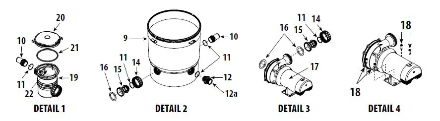
CLEARWATER II CARTRIDGE FILTER SYSTEM REPLACEMENT PARTS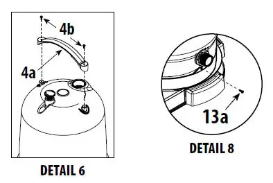
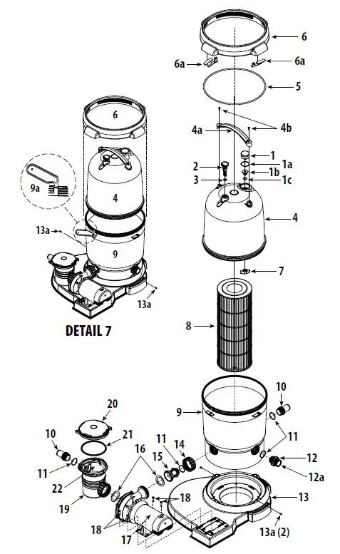
| Item | Part No. | Description | |
| 1 | 830-4000SS | Pressure Gauge | |
| 1a | 519-7431 | Pressure Gauge – Fitting Adapter | |
| 1b | 805-0117SD | O-Ring | |
| 2 | 602-0201 | Air Relief Plug | |
| 3 | 805-0207 | O-Ring – Air Relief | |
| 4 | 511-7321 | Lid Assembly – Small (75 / 100 sq. ft.) | |
| 511-7331 | Lid Assembly – Large (150 / 200 sq. ft.) | ||
| 4a | 519-7601 | Lid Handle | |
| 4b | 819-9002 | #12 x 3/4″ S/S Phillips-head Screw | |
| 5 | 805-0460 | Lid O-Ring | |
| 6 | 718-7251 | Filter Nut (sold with Lid Assembly only) | |
| 6a | 519-7451 | Lock-Tab (2) | |
| 7 | 519-7441 | Wing Nut | |
| 8 | 817-0075P | Cartridge – 75 sq. ft. | |
| 817-0100P | Cartridge – 100 sq. ft. | ||
| 817-0150N | Cartridge – 150 sq. ft. | ||
| 817-0200N | Cartridge – 200 sq. ft. | ||
| 9 | 515-7251 | Body – Filter Bottom | |
| 9a | 519-7470 | Filter Wrench (see Detail 6a) | |
| 10 | 417-6241 | 1 1/2″ MPT x 1 1/2″ Male Smooth Hose Adapter | |
| 11 | 805-0224 | O-Ring | |
| 12 | 500-5300 | Drain Assembly | |
| 12a | 505-2030 | Drain Cap | |
| 13 | 672-7401 | ClearWater II Base | |
| 13a | 819-0044 | #10 x 1″ S/S Phillips-head Screw | |
| 14 | 415-5001 | 2″ Union Nut | |
| 15 | 419-7241 | Coupling | 9a |
| 16 | 711-4010 | 2″ Union Gasket | |
| 17 | PH1100 | 1 HP – 1-Speed – Hi-Flo II Pump | |
| PH1150 | 1 1/2 HP – 1-Speed – Hi-Flo II Pump | 13a | |
| PH1200 | 2 HP – 1-Speed – Hi-Flo II Pump |
| PH2100 | 1 HP – 2-Speed – Hi-Flo II Pump | ||
| PH2150 | 1 1/2 HP – 2-Speed – Hi-Flo II Pump | ||
| PH2200 | 2 HP – 2-Speed – Hi-Flo II Pump | ||
| 18 | 429-7221 | Snap Pin | |
| 19 | 310-6500 | 6″ Trap – 1 1/2″ Buttress x 2″ Flange | |
| 20 | 319-3260 | 6″ Trap Lid | |
| 21 | 805-0436 | O-Ring | |
| 22 | 319-3230 | 6″ Basket Assembly | |
TROUBLESHOOTING
MOTOR DOES NOT START:
- Make sure the motor is plugged in.
- The circuit breaker in the OFF position.
- Thermal Overload in the tripped position.
- The wiring installation is incorrect.
- Incorrect line voltage.
- Defective wiring.
THERMAL OVERLOAD TRIPS:
- Low voltage.
- The wiring installation is incorrect.
- Dual voltage pumps miswired.
- Inadequate ventilation.
NO WATER FLOW:
- Obstruction of suction or return line.
- Clogged impeller.
- Suction system air leaks.
- Slice valve closed.
- Clogged hose fitting.
- Clogged basket.
- Dirty filter.
EXCESSIVE PUMP NOISE:
- Worn bearings.
- Suction line clogged.
- Pump incorrectly mounted.
- Hose fitting partially closed.
- Slice valve partially closed.
- Clogged trap basket.
INADEQUATE FILTERING:
- Inadequately cleaned system.
- Excessive dirt load.
- Chemical imbalance.
- Inadequate system pressure.
FILTER LEAKS:
- Dirty o-ring or gasket.
- Improperly seated o-ring or gasket.
- Missing o-ring or gasket.
- The filter nut was installed improperly.
WARRANTY
For product registration visit: www.waterwayplastics.com.
For Warranty questions or claims please contact the point of purchase.
2200 East Sturgis Road, Oxnard CA 93030
Phone 805.981.0262
Fax 805.981.9403
www.waterwayplastics.com
[email protected]


