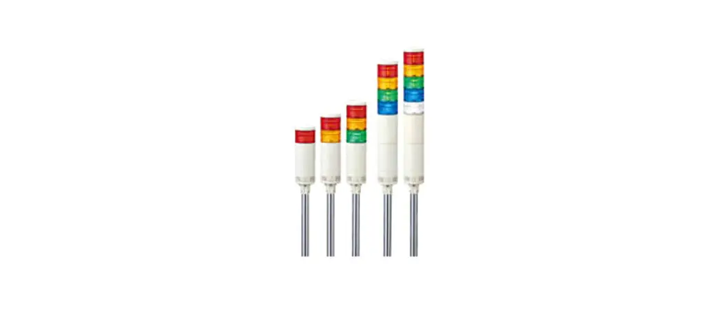
![]() Signal Tower
Signal Tower
Instruction Manual
Notice to Customer
Thank you very much for purchasing our PATLITE product.
- Request the installation and wiring be performed by a professional contractor if construction work is involved.
- Prior to installation, read this manual thoroughly before using this product to ensure correct use.
- After reviewing this manual, if there are any questions regarding this product, please contact the nearest PATLITE office listed on the back cover of this manual.
- Read this manual carefully prior to installation.
- Be sure to return this manual to the customer.
Safety Precaution
In order to prevent any damage to the user and other personnel or to assets, note the following: The following symbols classify the following precautions into two categories and explain the level of harm inflicted when caution is disregarded while using this product.![]() WARNING
WARNING
Indicates an immediately dangerous condition: failure to follow the instructions may lead to death or serious injury.![]() CAUTION
CAUTION
Indicates a potentially dangerous condition: failure to follow the instructions may lead to slight injury or property damage.
Safety Precautions
![]() WARNING
WARNING
- Make sure the power is off before wiring, repairing, or replacing parts to avoid a short-circuit, electric shock, or burn.
- Please use this product in a properly maintained
- condition. (If parts such as the Body or LED Unit are damaged, they should be repaired.)
- Do not use this product with the lens damaged or removed, or without the head cover in order to avoid an electric shock.
- If installing this product requires construction work, please ask a specialist in order to avoid electric shock, fire, or personal injury.
- When this product is used for security purposes, it should be inspected daily. In case a malfunction should occur, it is recommended that you use this product together with other security products.
- Do not use this product to support your weight while climbing onto a machine. Mount the product so that it is clear of any moving parts – such as a machine cover.
![]() CAUTION
CAUTION
- Concerning replacement parts, such as LED units, bulbs, or fuse, be sure to use those specified in this manual.
- For safety, make sure to connect an external fuse to the power source as shown in the wiring example.
- Do not substitute parts from other products as this may cause a breakdown.
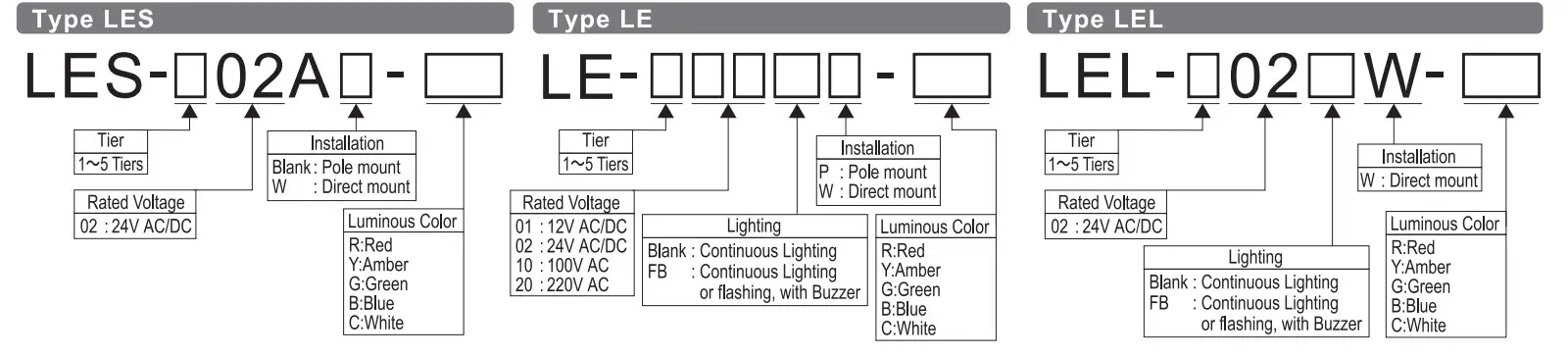
Model Number Configuration
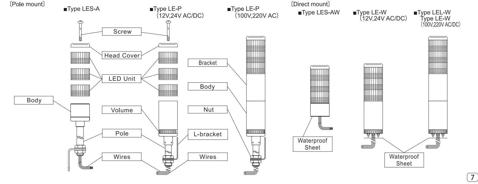
Part Names and Outer Appearance
Parts Name
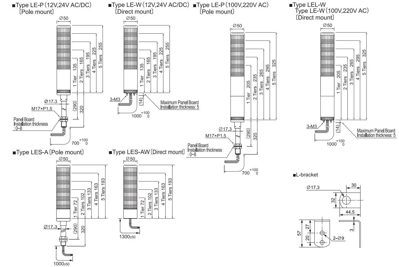
Dimensions
Installation
CAUTION
- The following requirements are necessary for proper installation.
• Install where no excessive vibration is present.
• Install on a strong surface.
• Install in an upright position. (Do not install the Signal Tower sideways or inverted.) - This product can only be used indoors. (Do not use it outdoors.)
- Use a soft cloth moistened with water when the LED Unit or Body must be cleaned up. (Do not use thinner, benzine, gasoline, or oil.)
- When installing this product, do not use excessive torque, or the product may be damaged.
- During installation, do not remove the waterproof sheet, it will increase possible water penetration and may cause a malfunction.
- This product also has mm-thick waterproof packing at the bottom of the pole bracket. However, because installation surface unevenness may cause a lack of waterproofing protection, it is recommended to apply waterproof sealant between the unit and the installation surface to maintain waterproof conditions.
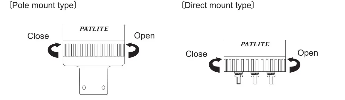
How to Install
- Drill mounting holes in the wall for L-bracket installation, or in the panel for direct mount installation.
- Secure the L-bracket with hex bolts and hex nuts (not supplied), or the accessory nuts (supplied).
*With buzzer models, the alarm can be heard best from the front direction. Therefore, make sure the Signal Tower is facing the correct direction before installation.
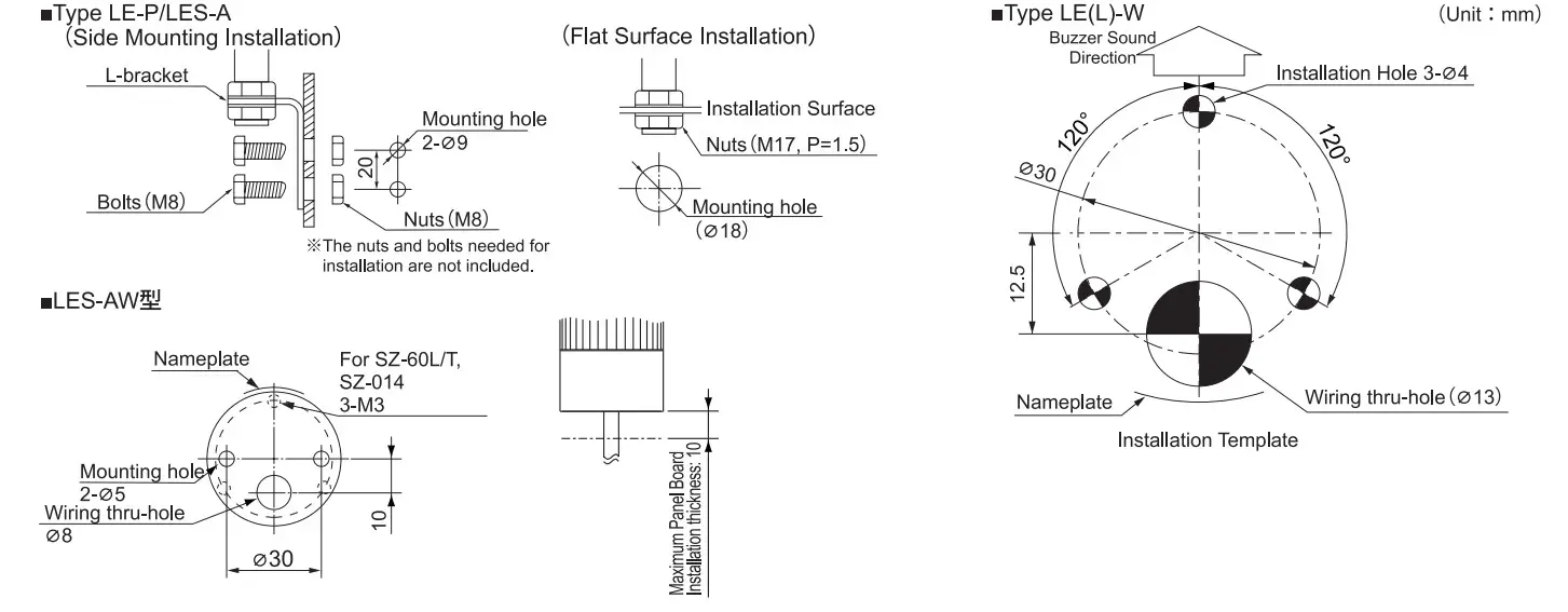
* When LES-W type is installed in pole bracket (SZ-60L/T type), Three screws(Pan head screw with flat and spring washer M3x7) are needed. When LES-W type is installed in the Bracket (SZ-014 type), Three screws(M3x6) are needed. (The tightening torque is about 0.59N •m.)
Using this template
- Verify the hole positions on the product.
- Secure the template onto the installation surface using adhesive tape.
- Mark the installation holes using a nail punch, etc.
- Drill the holes in the installation surface.
* Confirm the direction of the nameplate and the wiring route before you drill the holes.
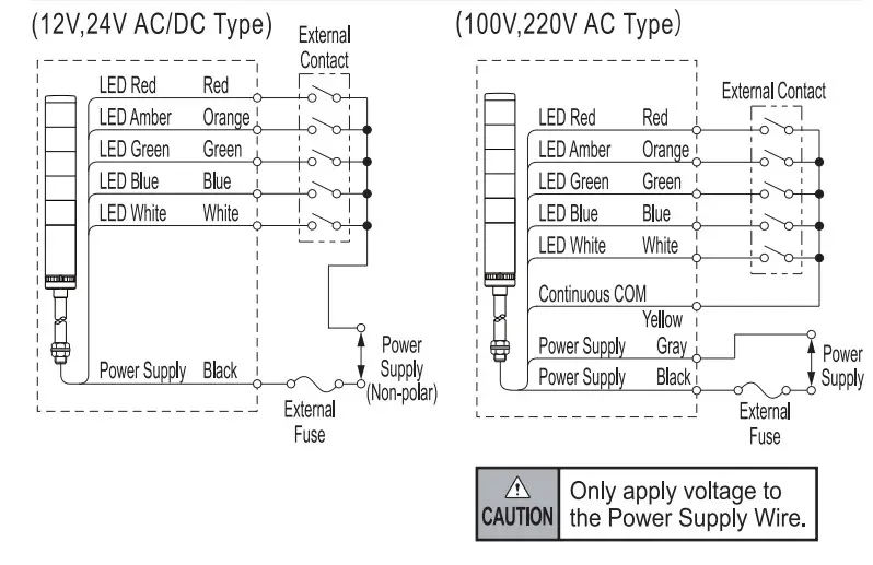
Wiring
![]() Caution
Caution
- Make sure the power is OFF before wiring. A short circuit may damage internal circuits or cause an electric shock.
- Enough attention shall be paid for wiring because if there is any mistakes in wiring a circuit may break down.
- Install the external contact fuse on the power supply side as shown in the wiring example in order to prevent bum in case of a wiring error.
- [100V/220VVAC Type] Do not apply voltage directly to signal wires and common wires. It may damage the circuit.
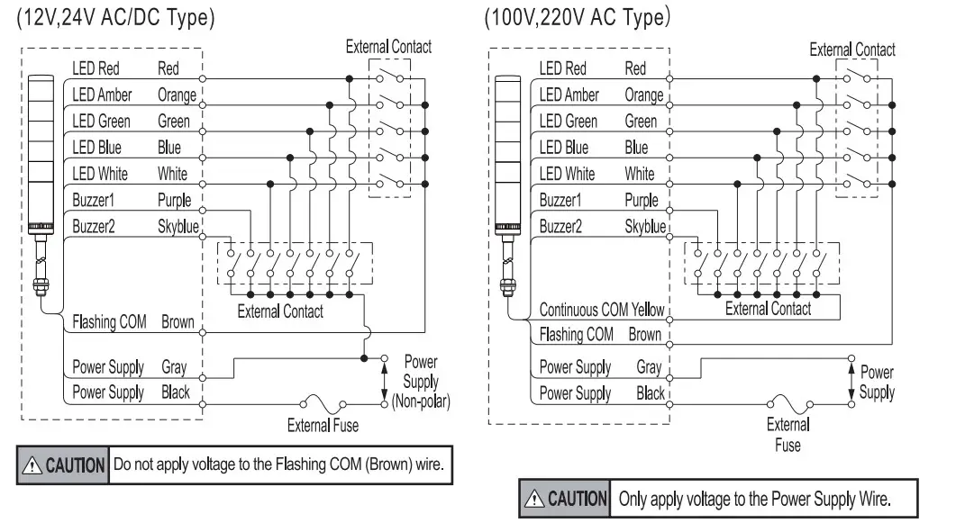
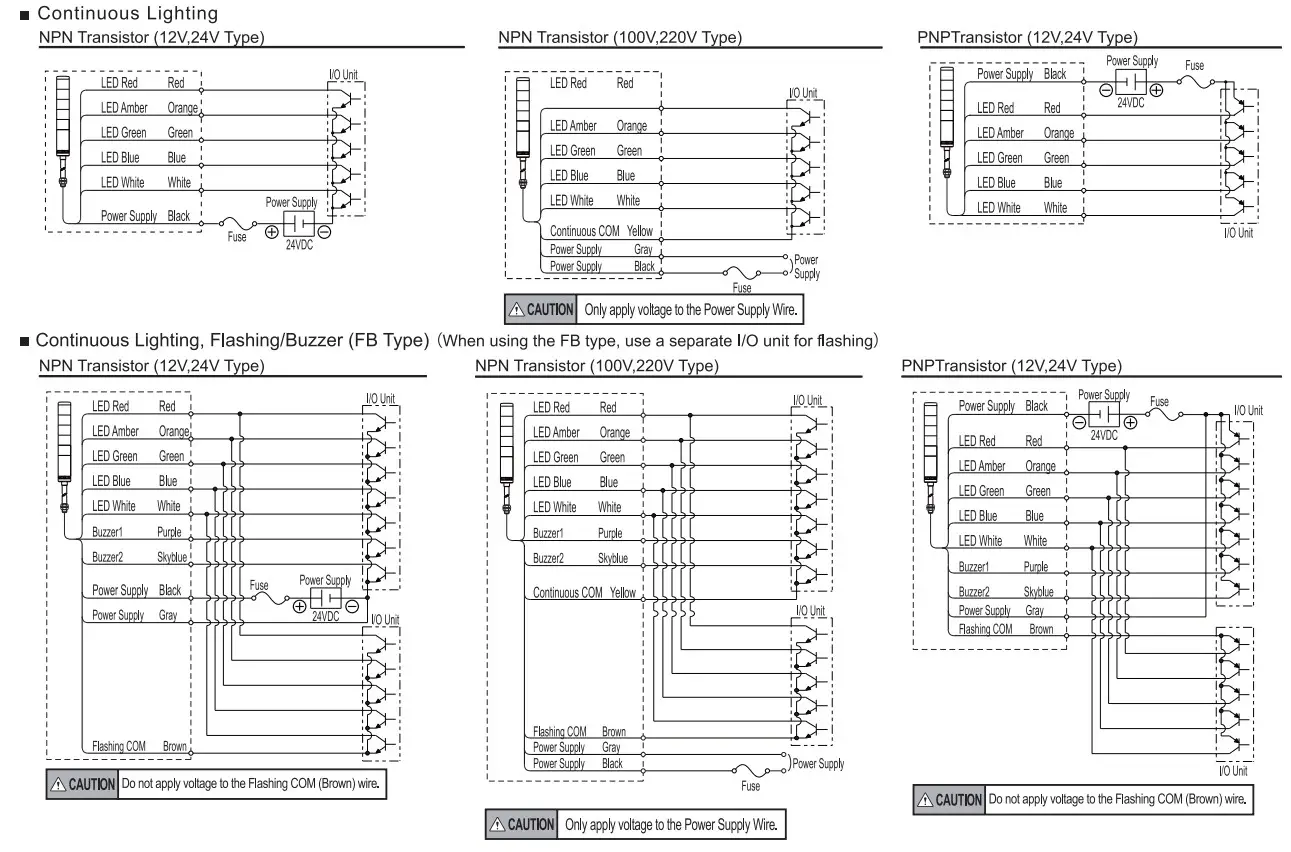
- Do not apply voltage directly to the brown wire. It may cause a breakdown.(FB type)
- Do not pull out the lead wire or push it into the pole or the body.
![]() Caution
Caution
- Simultaneously turn on the external contact for both constant lighting and flashing for the same light (color), may cause another light (color) to light up. To avoid this, provide separate switches for flashing or continuous lighting.
- When turning on the same function, such as flashing or alarms, for more than one product simultaneously, be sure to use separate external contacts for each product and function.
- When using both alarms sounds on one product, use separate contacts for the alarms and the lights.
How to perform wiring
- Turn the power OFF.
- Make wiring connection according to wiring example.
- When wiring 5 layers or less, please make wiring connections by increasing or decreasing external contacts in each layer according to wiring example.
- When using LED units of the same color, calculate the contact current capacity to be equal to the number of the LED units multiplied by the contact capacity for 1 light. (This is because current passes through one signal line for the LED units of the same color.)
- When wiring is completed, insulate the end of each unused lead wire with insulation tape.
- Any questions regarding applications for multiple units, or other special operations, contact your nearest PATLITE Sales Representative before wiring.
[To be recognized as a UL standard.]
- A fuse for protection of external contact should be installed within 305mm from the connecting point of the power source wire.
- Use a “Class 2 Circuit” for the power supply source (Type: 24V DC) and be sure to use the fuse and fuse holders authorized by UL, Inc.
- Use the fuse conforming to the rated current of the machine on which the product was installed. (Example: Class J type fuse)
Wire Color Table
Led Unit
| Luminous Color | Wire Color |
| Red | Red |
| Amber | Orange |
| Green | Green |
| Blue | Blue |
| White | White |
Buzzer (FB Type)
| Buzzer | Wire color |
| Buzzer: Continuous | Purple |
| Buzzer2: Intermittent | Skyblue |
- Lead wires are only included with the flashing/buzzer option. }
- Buzzer 1 is priority when connected simultaneously to common with buzzer 2.
External Contact Capacity
External Contact (Transistor) Capacity
| Voltage Specifications | 12V AC/DC | AC/DC 24V | AC 100V | AC 220V | |
| LED Unit (Per Light) | Current Consumption | Red • Amber: 43.0mA Green • Blue • White: 24.0mA | Red • Amber: 25.0mA Green • Blue • White: 14.8mA | ||
| Contact Capacity | Is? 100mA, Vs a 30V AC | Isa 50mA, Visa 50V AC | |||
| Buzzer | Current Consumption | 40mA | |||
| Inrush Current | 2A | 250mA | |||
| Contact Capacity | Isa300mA, Vs_Z’50V AC | ||||
| Power Supply | Current Consumption | 400mA | 360mA | 40mA | 20mA |
| Contact Capacity | Isa500mA Vsa30V AC | Isa 500mA Vs a 50V AC | Is a 100mA Vsa 125V AC | Isa 50mA Vs a 250V AC | |
| Leakage Current | ILS0.1mA | ||||
External Fuse
| Voltage | Fuse Rating |
| All Model | 250V 1A |
3X Use the fuse conforming to the rated current of the machine in which the product was installed. (Example: Class J type fuse)
Wiring Example
LE(L)/LES [Continuous Lighting] Type
LME-FB [Continuous Lighting, Flashing/Buzzer] Type
Wiring Example (NPN/PNP Transistor drive)
 Charging LED Unit Position
 Charging LED Unit Position
![]() CAUTION
CAUTION
- Make sure the power is off before wiring, repairing, or replacing parts to avoid a short-circuit, electric shock, or burn.
- Do not remove the LED unit forcibly as it may damage the unit.
- When the center screw is loosened or removed, the LED units become unstable and may separate. Therefore, handle carefully to avoid dama
- Handle the LED units carefully to avoid warping or damage when changing their positions on the tower.
- Screwing the head cover too tight may damage it. The recommended torque is about 0.59N-m.
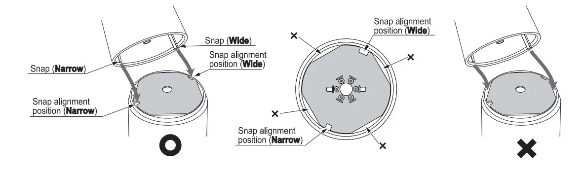
Charging LED Unit Position
- Turn the power off before changing LED unit positions.
- Unscrew the head cover and remove the lens.
- Each LED unit is secured by 2 small snaps of different sizes to ensure that the module is assembled correctly.
- When changing the number of modules, install a center screw to match the number of tiers.
- LES-A has the lead wires of the adapted LED module for the factory default color only.
The LED module of LES-A cannot be adapted, removed, or interchanged. - In the case of LES Type, the bottom LED unit can not be removed or interchanged.
Volume Adjustment
![]() CAUTION
CAUTION
- Do not move the lever forcibly as it may damage the volume control.
Volume Adjustment
- The volume can be adjusted by moving the lever near the bottom of the base to the left or right.
- The volume is at maximum when the lever is positioned right side. :
Specification
Type LE
| Tiers | Model | UL Registration Model | Rated Voltage | Power Consumption | Mass | Flash Cycle (fpm) and sound level | Wire type /Diameter |
| 1 Tier | -101(FB)P/W | LE- 01 (FB)P/W | 12V AC/DC | 12,24V Type Red • Amber • Blue• White : 0.6W Buzzer : 0.5W (12V) 1.0W (24V) 100V,220V Type Red .Amber: 1.0W Green. Blue•White: 0 8W Buzzer: 1.2W Standby : 3.5W | 0.69kg(P) 0.31 kg(W) | Flashing cycle FB Type 60 Flashes per minute Sound level FB Type 70„85 dB (1 m) | (12,24V Type) Black wire UL1007AWG20 Others UL1007/AWG22 (100,220V Type) Power source wire UL1007AWG20 Lead wire UL1007AWG22 |
| -102(FB)PNV | LE- 02(FB)P/W | 24V AC/DC | |||||
| -110(FB)P/W | x | 100V AC | 0.78kg(P) 0.40kg(W) | ||||
| -120(FB)P/W | x | 220V AC | |||||
| -201(FB)PNV | LE-01 (FB)PNV | 12V AC/DC | 0.74kg(P) 0.36kg(W) | ||||
| -202(FB)PNV | LE- 02(FB)P/W | 24V AC/DC | |||||
| -210(FB)P/W | x | 100V AC | 0.83kg(P) 0.45kg(W) | ||||
| -220(FB)PNV | x | 220V AC | |||||
| 3 Tiers | -301(FB)P/W | LE- 01 (FB)PNV | 12V AC/DC | 0.79kg(P) 0.41 kg(W) | |||
| -302(FB)P/W | LE- 02(FB)P/W | 24V AC/DC | |||||
| -310(FB)P/W | x | 100V AC | 0.88kg(P) 0.50kg(W) | ||||
| -320(FB)P/W | x | 220V AC | |||||
| 4 Tiers | -401(FB)PNV | LE- 01 (FB)P/W | 12V AC/DC | 0.84kg(P) 0.46kg(W) | |||
| -402(FB)P/W | LE- 02(FB)P/W | 24V AC/DC | |||||
| -410(FB)P/W | x | 100V AC | 0.93kg(P) 0.55kg(W) | ||||
| -420(FB)P/W | x | 220V AC | |||||
| 5 Tiers | -501(FB)P/W | LE- 01 (FB)PNV | 12V AC/DC | 0.89kg(P) 0.51 kg(W) | |||
| -502(FB)P/W | LE- 02(FB)P/W | 24V AC/DC | |||||
| -510(FB)P/W | x | 100V AC | 0.98kg(P) 0.60kg(P) | ||||
| -520(FB)PAN | x | 220V AC |
Type LEL
| Tiers | Model | UL Registration Model | Rated Voltage | Power Consumption | Mass | Flash Cycle (fpm) and sound level Wire type | /Diameter |
| 1 Tier | -102(FB)W | LEL-_02(FB)W | 24V AC/DC | Red • Amber Green • Blue • White: 0.6W Buzzer: 1.0W | 0.31kg | FB Type Flashing cycle 60 Flashes per minute Sound level 70-45 dB (1m) | UL1007/AWG22 |
| 2 Tiers | -202(FB)W | 0.36kg | |||||
| 3 Tiers | -302(FB)W | 0.41kg | |||||
| 4 Tiers | -402(FB)W | 0.45kg | |||||
| 5 Tiers | -502(FB)W | 0.51 kg |
Type LES
| Tiers | Model | UL Registration Model | Rated Voltage | Power Consumption | Mass | Wire type /Diameter |
| 1 Tier | -102A(W) | LES-_02A(W) | 24V AC/DC 0.50kg 0.62kg | Red • Amber • Green White: Blue • 0.6W | 0.07kg(W) | UL1007/AWG20 |
| 2 Tiers | -202A(W) | 0.53kg 0.10kg(W) | ||||
| 3 Tiers | -302A(W) | 0.56kg 0.13kg(W) | ||||
| 4 Tiers | -402A(W) | 0.59kg 0.16kg(W) | ||||
| 5 Tiers | -502A(W) | 0.19kg(W) |
- This product is recognized as a UL standard. (12V, 24V AC/DC type)
For recognition as a UL standard;
– Use on a flat surface with a Type 1 Enclosure.
– Maximum surrounding air temperature is at 60°C. - This product conforms to EN standards and shows the CE Marking. (12V, 24V AC/DC type)
This product has been tested and found to comply with the limits for a Class A device, pursuant to EMC DIRECTIVE.
These limits are designed to provide reasonable protection against harmful interference when the equipment is operated in a commercial environment.
This product must not be used in residential areas.
Caution
- PATLITE Corporation disclaims all liability for any malfunction or damage occurring as a result of handling contrary to the instructions, cautions, and warnings mentioned in this manual.
- Specifications may change without notice due to continual product improvement.
PATLITE Corporation
PATLITE Corporation Head office http://www.patlite.com/
PATLITE (U.S.A.) Corporation http://www.patlite.com/
PATLITE Europe GmbH XGermany 9 WM http://www.patlite.eu/
PATLITE (SINGAPORE) PTE UTD # http://wwwpatlite.com/
PATLITE (CHINA) Corporation B http://www.patlite.cn/
PATLITE KOREA CO.,LTD. B http://www.patlite.co.kr/
PATLITE TAIWAN CO., LTD. B http://www.patlite.tw/
PATLITE (THAILAND) CO.,LTD. § W http://www.patlite.co.th/


