![]()
GA0009717_01
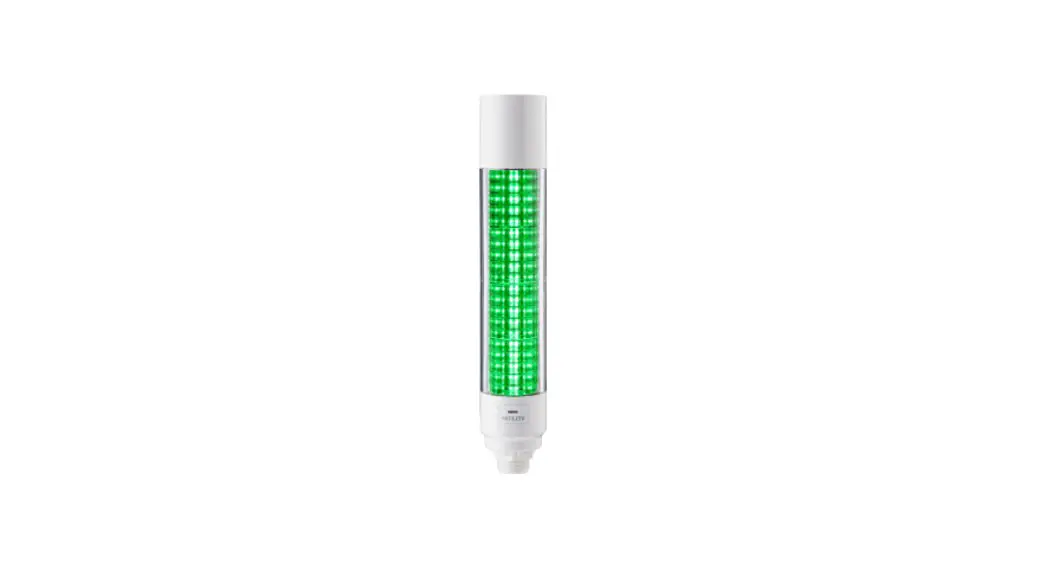
Multi-color Signal Tower with ![]() IO-Link
IO-Link
TYPE LB6-IL
General Instruction Manual
Installation Operation Maintenance
LB6-IL IO-Link Signal Tower
Notice to Customer
Thank you very much for your purchasing our PATLITE products.
- Request the installation and wiring be performed by a professional contractor if construction work is involved.
- If there are any questions concerning this product, refer to the contact information at the end of this document and contact your nearest PATLITE Sales Representative.
To the Contractor
- Read this manual carefully prior to installation.
Read this First
Safety Precautions
The safety precautions that should always be followed in order to prevent injury to user or other individuals as well as prevent damage to property are described below.
■ The level of injury or damage caused by ignoring these safety precautions and using the product improperly is categorized and described below.
![]() Warning
Warning
This icon indicates an action with the potential to cause death or serious injury.
![]() Caution
Caution
This icon indicates an action with the potential to cause injury, physical loss or damage.
![]() Warning
Warning
- Observe the following to prevent short-circuits and damage.
- Turn off the power before wiring or repairs, including replacement of the fuse.
- Install the product correctly. (Replacement in case of damage to glove or case.)
- Request the installation and wiring to be accompanied by a professional contractor.
If installation is done improperly, it may result in fire, electric shock, falling, or malfunction. - When this product is used for security purposes, it should be inspected daily. In case a malfunction should occur, it is recommended that you use this product together with other security products.
- After installation, do not use this product to climb up onto the equipment with.
Failure to comply will result in product damage and/or falling off the machinery.
![]() Caution
Caution
- Before handling static-sensitive parts of this product, discharge any static electricity from the body.
- Do not disassemble or remove during operation.
- When you attach/detach the head cover and buzzer unit, do not touch the internal connector terminal.
Failure to follow this instruction may cause a breakdown.
Notice
- When using this product for sequrity purposes, please observe the following.
- Be sure to conduct daily inspections.
- Use in conjunction with other crises in case of failure.
- Before handling static-sensitive parts of this product, discharge any static electricity from the body. (To prevent damage from static electricity, place your hand or other body part onto a metal object or to an earth ground.)
- Use a soft cloth moistened with water to wipe off any dirt or grime on the main unit. (Do not wipe with thinners, benzine, gasoline, or oil.)
- Observe the following when handling product parts.
- Other than parts that you can remove, do not disassemble any parts.
- Do not modify this product.
- Be sure to use the repair parts specified in this manual.
Model Number Configuration
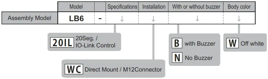
Example LB6-20ILWCBW
- 20Seg. / IO-Link Conterol
- Direct Mount / M12 Connector
- with Buzzer
- Off white
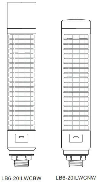
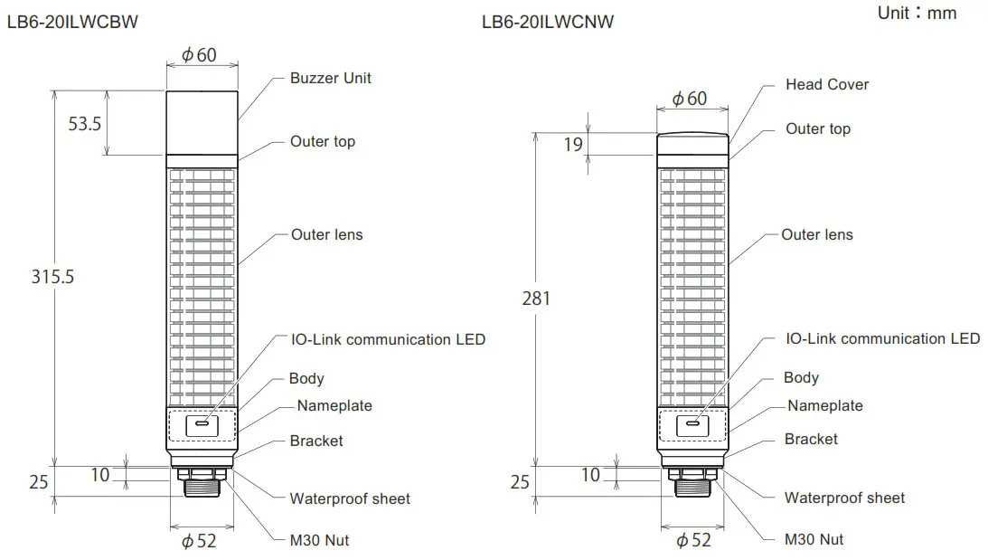
Names and Dimensions
Installation
![]() Caution
Caution
- This product is for indoor use only.
- Do not use the product with the Head cover or Buzzer unit removed.
- Do not apply excessive force when installing or removing the head cover and buzzer unit.
Failure to do could result in damage to the unit. - When removing and reinstalling the head cover and buzzer unit, make sure there is no floating between them and the outer lens. Failure to do so may result in parts falling or flooding.
- Use a soft cloth moistened with water to wipe off any dirt or grime on the main unit.
- Be sure to install the provided waterproof sheet when installing the product.
- When the installation location is unavoidably irregular and waterproof performance is required, use a sealant between the product and the installation surface.
Notice
- The following requirements are necessary for a proper mounting location.
- Location with strong and even surface with minimal vibration.
- When the installation location is unavoidably irregular and waterproof performance is required, use a sealant between the product and the installation surface.
- Check the mounting position of the product.
- Make a mounting hole in the mounting position of the product. ( See P.5 ”■Mounting Surface Dimensions” )
- Turn the body in the counterclockwise direction and remove the body from the bracket.
- Remove the M30 nut from the bracket.
- Attach the bracket to the mounting position.
- Secure the bracket to the mounting position with the M30 nut.
Recommended tightening torque 4.5N・m - Pass the M12 cable through.
- Align the M12 cable alignment with the M12 connector alignment to attach the M12 cable. ( See P.4 “3 Names and Dimensions M12 Connector Pin Configuration” )
- Turn the body in the clockwise direction and mount the body to the bracket.
■ Mounting Surface Dimensions [Unit : mm]
- Check the mounting position of the product and the NPT pole.
- Turn the body in the counterclockwise direction and remove the Body from the bracket.
- While holding part ‘A’, attach the Bracket to the NPT pole.
Recommended tightening torque 2.25N・m - Pass the M12 cable through.
- Align the M12 cable alignment with the M12 connector alignment to attach the M12 cable. ( See P.4 “3 Names and Dimensions M12 Connector Pin Configuration ”)
- Turn the body in the clockwise direction and mount the body to the bracket.
Wiring
![]() Caution
Caution
- Turn off the power before wiring. There is a risk of short-circuiting and damage to the internal circuitry.
- Ensure the proper working voltage is used and that direct current or alternating current is properly applied. Any mistake in wiring may result in damage.
- Do not pull the wire. Possible cause of failure may occur.
- Be sure the wiring is done properly. Any mistake in wiring may result in damage.
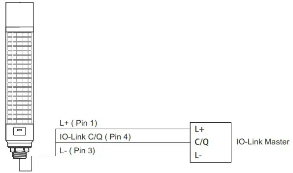
How to Use
This product is IO-Link supported.
Wire according to P.6 ”5 Wiring”.
LED and buzzer can be controlled from the IO-Link master.
By changing the “Operating Mode” setting, the unit can operate in the following modes.
- Simple Mode
- Level Mode
- Animation Mode
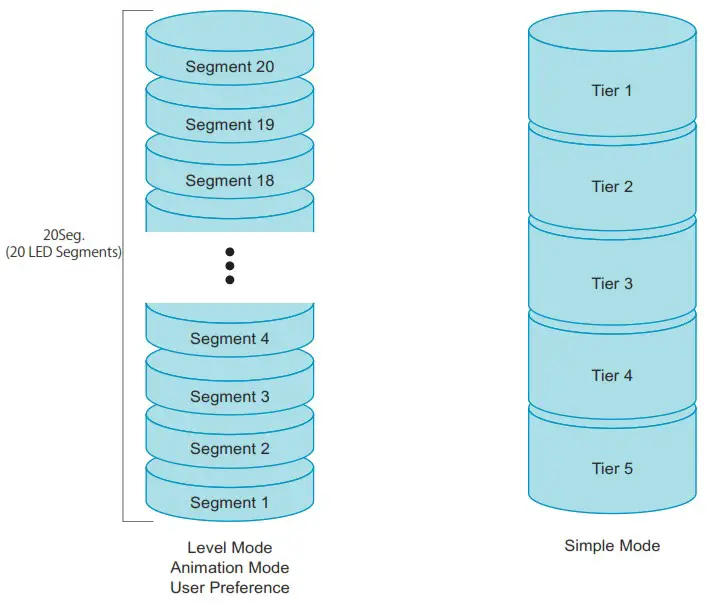
In level mode, animation mode and user preferences, the LEDs are controlled segment by segment.
In simple mode, several segments are controlled as a single tier.
The number of segments per tier can be set arbitrarily. (See P.11 □Size of Tiers)
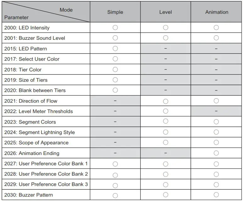
The parameters used in each mode are listed in the table below.
For common matters, see P.14 ” ■Matters common to all mode ”.
■ Parameter setting
For parameters, download and use the IODDs on the Type LB6 page of the website (https://www.patlite.com).
Also download and use the parameter sheet in the same way.
■ Simple Mode
This mode allows control by setting the contents of the LED and the buzzer.
Other settings are made via parameters.
Refer to the table below for process data transmission.
| bit7 | bit6 | bit5 | bit4 | bit3 | bit2 | bitl | bit0 | |
| Byte 0 | User Preference Select | Buzzer ON/OFF | LED Tier 5 ON/OFF | LED Tier 4 ON/OFF | LED Tier 3 ON/OFF | LED Tier 2 ON/OFF | LED Tier 1 ON/OFF | |
| Byte 1 | Not used | |||||||
□LED pattern
The “LED Pattern” used in simple mode corresponds to the table below.
| Pattern | Set Value | |
| Name | Flashing Rate | |
| Continuous | 0 | |
| Blinking Slow | 30 blinks per minute | 1 |
| Blinking Middle | 90 blinks per minute | 2 |
| Blinking Fast | 120 blinks per minute | 3 |
| Flashing Slow | 60 flashes per minute | 9 |
| Flashing Middle | 90 flashes per minute | 10 |
| Flashing Fast | 120 flashes per minute | 11 |
| Gradation blinking Slow | 60 blinks per minute | 12 |
| Gradation blinking Middle | 90 blinks per minute | 13 |
| Gradation blinking Fast | 120 blinks per minute | 14 |
□ Select User Color
“Select User Color” allows you to select an arbitrary LED colour to be used in Simple mode.
See P.14 “□About LED Color” for the color to be selected.
□ Tier Color
“Tier Color” corresponds to the table below.
| LED Color | Set Value |
| Off | 0 |
| Red | 1 |
| Green | 2 |
| Amber | 3 |
| Blue | 4 |
| Purple | 5 |
| Cyan | 6 |
| White | 7 |
| User Color* | 8 |
* Selected in ”Select User Color” parameter
Default values are shown in the table below.
| Tier | Set value |
| Tier 1 | 1 (Red) |
| Tier 2 | 3 (Amber) |
| Tier 3 | 2 (Green) |
| Tier 4 | 4 (Blue) |
| Tier 5 | 7 (White) |
□ Size of Tiers
The number of segments controlled as one tier can be changed using the “Size of Tiers”.
Default values are all 4.
Set the total value to be 20.
■ Level Mode
In this mode, LED and buzzer contents are set by parameters and controlled by process data values.
Refer to the table below for process data transmission.
| bit7 | I bit6 | bit5 | bit4 | I bit3 | I bit2 | I bitl | I bib) | |
| Byte 0 | User Preference Select | Buzzer ON/OFF | Not used | |||||
| Byte 1 | Not used | Level value* Ox00 – 0x64 (0 – 100) | ||||||
*Level values are valid from 0 to 100; for values greater than 100, the level value is 100.
□ Default value
The default values of the parameters in level mode are shown in the table below.
| Segment | Threshold | LED Color | LED Pattern |
| 20 | 95 | Red | Flashing Fast |
| 19 | 90 | Red | Flashing Fast |
| 18 | 85 | Red | Flashing Fast |
| 17 | 80 | Red | Flashing Fast |
| 16 | 75 | Amber | Flashing Middle |
| 15 | 70 | Amber | Flashing Middle |
| 14 | 65 | Amber | Flashing Middle |
| 13 | 60 | Amber | Flashing Middle |
| 12 | 55 | Green | Blinking Fast |
| 11 | 50 | Green | Blinking Fast |
| 10 | 45 | Green | Blinking Fast |
| 9 | 40 | Green | Blinking Fast |
| 8 | 35 | Cyan | Blinking Slow |
| 7 | 30 | Cyan | Blinking Slow |
| 6 | 25 | Cyan | Blinking Slow |
| 5 | 20 | Cyan | Blinking Slow |
| 4 | 15 | Blue | Continuous |
| 3 | 10 | Blue | Continuous |
| 2 | 5 | Blue | Continuous |
| 1 | 0 | Blue | Continuous |
■ Animation Mode
In this mode, the LED and buzzer contents are set by parameters, and the level mode is displayed sequentially.
Refer to the table below for process data transmission.
| bit7 | I bit6 | bit5 | bit4 | bit3 | bit2 | bit1 | bit0 | |
| Byte 0 | User Preference Select | Buzzer ON/OFF | Not used | Animation Reset Animation | Enable | |||
| Byte 1 | Not used | Animation Speed | ||||||
□ Animaition Ending
“Animation Ending” selects the motion after all segments are lighting up in animation mode.
Refer to the table below to set this parameter.
| Motion | Set value |
| All segments turn off and animation starts again | 0 |
| Segments turn off in the opposite order of lights on, and animation starts again | 1 |
□ Animation Reset
Stops the running animation and plays it back from the start.
If this bit is set, the animation is reset and does not start.
■ Matters common to all mode
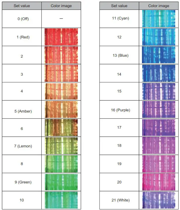
□ LED Color
The “LED Color” used in each mode corresponds to the table below.
Color images may differ from actual colors due to screen conditions or printing conditions.
□ Buzzer Pattern
“Buzzer Pattern” used in each mode corresponds to the table below.
| Pattern | Set value |
| Off | 0 |
| Continuous Beep Sound | 1 |
| Rapid Intermittent Beep | 2 |
| Rapid Hi-Low | 3 |
| Sweep Sound | 4 |
| Continuous Beep Sound 500ms ON / 500ms OFF | 5 |
| Rapid Intermittent Beep 500ms ON / 500ms OFF | 6 |
| Rapid Hi-Low 500ms ON / 500ms OFF | 7 |
| Sweep Sound 500ms ON / 500ms OFF | 8 |
□ LED Intensity
“LED Intensity” used in each mode can be set from 0 to 100% in 10% increments.
□ Buzzer Sound Level
“Buzzer Sound Level” used in each mode can be set from 0 to 100% in 10% increments.
□ Direction of Flow (Level Mode, Animation Mode)
“Direction of Flow” sets the starting position of the lighting.
Refer to the table below for the setting.
| Starting position | Set value |
| Starts lighting from segment 1 | 0 |
| Starts lighting from segment 20 | 1 |
□ Scope of Apperance (Level Mode, Animation Mode)
Each segment lights up with the LED color/LED pattern set.
Except for the top segment, the color and pattern of the LEDs in the illuminated segments change according to the “Scope of Appearance” setting.
Refer to the table below for the settings.
| Motion | Set value |
| Lighting with the same LED color/pattern as the top segment | 0 |
| Lighting with set LED colors/pattern | 1 |
| Continuous lighting with set LED color | 2 |
□ User Preference
Set a value of 1~3 in “User Preference” in the process data, and the operation set in User Preference Color1~3 will be performed.
Regardless of each mode or process data value (except the buzzer setting), the display set in the user preferences takes priority.
Troubleshooting
Troubleshoot problems that occur by following the instructions in the table below.
| No. | Problem | Confirmation | Remedy |
| 1 | The LED does not light | Is the processing data correct? | Please check’6 How to Use” (P.8) before submitting your process data. |
| Are the parameters correct? | Please check ” 6 How to Use” (P.8) before set value. | ||
| Is the electric wiring connected correctly? | Refer to “5 Wiring” (P.7) for proper wiring. | ||
| Is the power supply applied at the correct voltage? | Check voltage output from the connected master. | ||
| 2 | The color of the LED differs from the desired color. | Is the processing data correct? | Please check “6 How to Use” (P.8) before submitting your process data. |
| Are the parameters correct? | Please check “6 How to Use” (P.8) before set value. | ||
| 3 | The buzzer does not sound. | Is the processing data correct? | Please check’6 How to Use” (P.8) before submitting your process data. |
| Are the parameters correct? before set value. | Please check ” How to Use” (P.8) | ||
| Is the electric wiring connected correctly? | Refer to “5 Wiring” (P.7) for proper wiring. | ||
| Is the power supply applied at the correct voltage? | Check voltage output from the connected 10-Link master. |
Specifications
General Specifications
| Product Name | Multi-color Signal Tower with 10-Link | ||
| Model | LB6-20ILWCNW | I LB6-20ILWCBW | |
| Rated Voltage | 24V DC | ||
| Operating Voltage Range | 18V – 30V DC | ||
| Current Consmption | Std. | 200mA | 250mA |
| Max. | 250mA | 300mA | |
| Condition | At rated voltage, with 10-Link communication. All LED segments continuously illuminate in white. Dimming:100% (Only LB6-20ILBW)Buzzer Sound “Continuous Beep Sound” Volume:100% | ||
| Inrush Current | None | ||
| Operating Ambient Temperature | -20°C ~ +50°C | ||
| Operating Ambient Humidity | Less than 90% (No condensation) | ||
| Storage Ambient Temperature | -30°C ~ +60°C | ||
| Storage Ambient Humidity | Less than 90% (No condensation) | ||
| Mounting Location | Indoor | ||
| Mounting Direction | Upright | ||
| Protection Rating | IP65 | ||
| Environmental Condition | Upright | ||
| Insulation Resistance | More than 5M0 at 500VDC between live part and non-current carrying metallic part | ||
| Withstand Voltage | 500VAC applied for 1min between live part and non-current carrying metallic part without breaking insulation | ||
| Dimensions | See “3 Names and Dimensions” | ||
| Mass(Tolerance:±10%) | 0.54kg | I 0.59kg | |
| Conformity Standards | UL 508, CSA C22.2 No. 14 | ||
| EN 61000-6-4. EN 61000-6-2. EN IEC 63000 | |||
| FCC Part 15 Subpart Class A | |||
| ICES-003 Class A | |||
| Remarks | • Due to the characteristics of the LED elements. there may be a slight variation in color tone and brightness between products. • UL Recognized Component(File No.E215660) • Conforms to the CE requirements. • Conforms to the UKCA requirements. | ||
• The requirements in each law and regulation are only included in the language designated by each law and regulation.
Check the instruction manuals published in each language.
LED Specifications
| Lighting color | No.1 | Red | No.8 | (Lemon to Green Gradation) | No.15 | (Blue to Purple Gradation) |
| No.2 | (Red to Amber Gradation) | No.9 | Green | No.16 | Purple | |
| No.3 | No.10 | (Green to Cyan Gradation) | No.17 | (Purple to White Gradation) | ||
| No.4 | No.11 | Cyan | No.18 | |||
| No.5 | Amber | No.12 | (Cyan to Blue Gradation) | No.19 | ||
| No.6 | Amber to Lemon Gradation) | No.13 | Blue | No.20 | ||
| No.7 | Lemon | No.14 | (Blue to Purple Gradation) | No.21 | White | |
| Lighting pattern | Continuous, Blinking, Gradation blinking, Flash | |||||
| Flashing Rate (Typ.) | Blinking | 30 / 90 / 120 times/min | ||||
| Gradation blinking | 30 / 90 / 120 times/min | |||||
| Flash | 60 / 90 / 120 times/min | |||||
Buzzer Specifications
| Buzzer Sound / Typical Frequency | No.1 | OFF |
| No.2 | Continuous beep sound / 3,378Hz | |
| No.3 | Rapid intermittent beep / 3,378Hz | |
| No.4 | Rapid Hi-Lo / 2,016Hz & 3,012Hz | |
| No.5 | Sweep sound / 1,000Hz – 4,032Hz | |
| No.6 | Continuous beep sound / 3,378Hz 500ms ON / 500ms OFF | |
| No.7 | Rapid intermittent beep / 3,378Hz 500ms ON / 500ms OFF | |
| No.8 | Rapid Hi-Lo / 2,016Hz & 3,012Hz 500ms ON / 500ms OFF | |
| No.9 | Sweep sound / 1,000Hz – 4,032Hz 500ms ON / 500ms OFF | |
| Setting | Depending on 10-Link parameters | |
| Sound Pressure Level (Typ.) | 88dB | |
| Environmental Condition | Buzzer sound No.5 is measured from the total circumfrence of the buzzer Unit at 1 m. (Volume:100%) | |
IO-Link Specifications
| Function | LED Segment Control | Operation Mode | Simple Mode/ Level Mode / Animation Mode |
| Lighting Color | Total 21 colors | ||
| Lighting Control | Total 10 patterns | ||
| Dimming | 0% to 100% (10% step) | ||
| Buzzer Control | Buzzer Style | Total 9 styles (Including “OFF”) | |
| Volume | 0% to 100% (10% step) | ||
| Communication specification | 10-Link revision | 1.1.3 | |
| Transmission rate | COM2 | ||
| Minimum Cycle time | 2.7ms | ||
| Process data length | PD out : 2byte PD in : Obyte | ||
| ID | Vendor | 763d(Ox2FB) | |
| Device | 524290d(0x80002) | ||
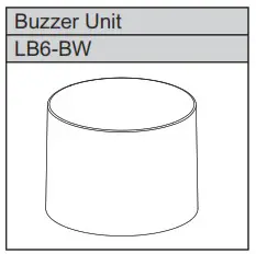
Replacement Parts
The following replacement parts for this product are available for customer to change or replace.
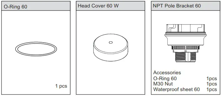
Option Parts
The optional parts for this product are listed below. (Top line: Part Name; Bottom: Model)
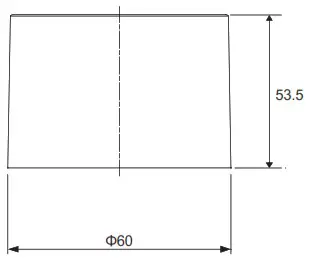
External Diagram (Unit: mm)
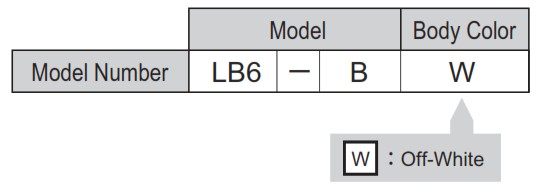
Model Number Configuration
General Specifications
| Model | LB6-B | |
| Ambient operating temperature | -20°C ~ +50°C | |
| Ambient operating humidity | Less than 90 % (No condensation) | |
| Mass(Tolerance±10%) | 0.06kg | |
| Buzzer Sound / Typical Frequency | No.1 | OFF |
| No.2 | Continuous beep sound / 3,378Hz | |
| No.3 | Rapid intermittent beep / 3,378Hz | |
| No.4 | Rapid Hi-Lo / 2,016Hz & 3,012Hz | |
| No.5 | Sweep sound / 1,000Hz – 4,032Hz | |
| No.6 | Continuous beep sound / 3,378Hz 500ms ON / 500ms OFF | |
| No.7 | Rapid intermittent beep / 3,378Hz 500ms ON / 500ms OFF | |
| No.8 | Rapid Hi-Lo / 2,016Hz & 3,012Hz 500ms ON / 500ms OFF | |
| No.9 | Sweep sound / 1,000Hz – 4,032Hz 500ms ON / 500ms OFF | |
| Setting | Depending on 10-Link parameters | |
| Sound Pressure Level (Typ.) | 88dB | |
| Environmental Condition | Buzzer sound No.5 is measured from the total circumfrence of the buzzer Unit at 1m (Volume:100%) | |
Attach/detach the Buzzer Unit
Follow the instruction below when attaching and detaching the buzzer unit.
![]() Warning
Warning
- Be sure that it is disconnected from the power source before working on it
![]() Caution
Caution
- Do not apply excessive torque or strong shock to each unit or body. Failure to comply will result in damage or malfunction.
- Do not touch the connector area or the inside of the body. Failure to comply will result in damage or malfunction.
- Be sure to lock buzzer unit securely when attaching. Failure to comply will result in damage or malfunction.
- The buzzer unit must be removed by holding the product body. Failure to comply will result in damage.
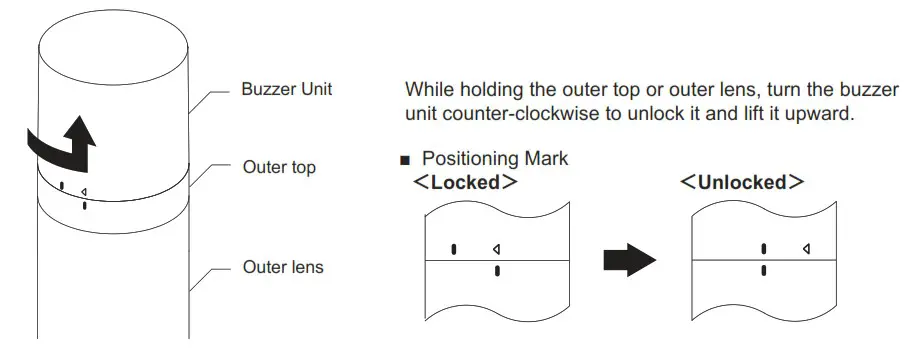
■ Detachment
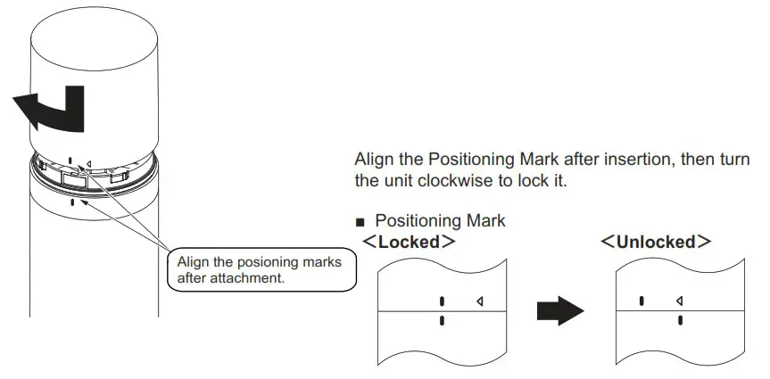
■ Attachment
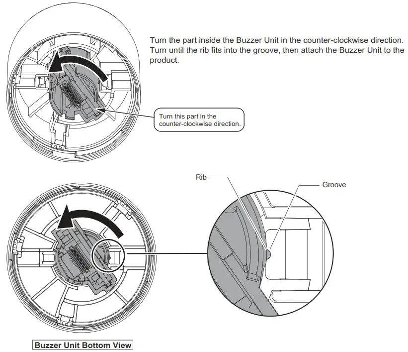
<Troubleshooting the Buzzer Unit Attachment>
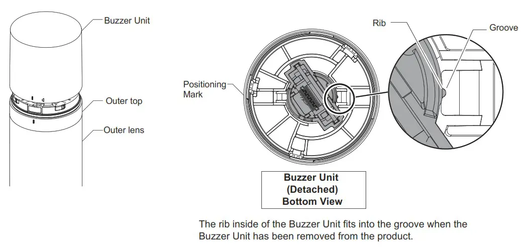
The Buzzer Unit is generally in the status shown in the diagram below after removal.
![]() Caution
Caution
Check to make sure the rib inside of the Buzzer Unit fits into the groove if the Buzzer Unit does not attach properly.
Attach the Buzzer Unit by referring to the next page if the rib does not fit into the groove as shown in the diagram below. In addition, the rib may slide out of the groove during removal as shown in the diagram below depending on how the Buzzer Unit was removed. Attaching the Buzzer Unit to the product again in this state may result in damage.
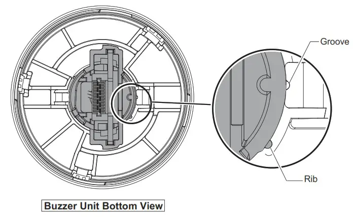
Use the procedure below if the Buzzer Unit does not attach properly.
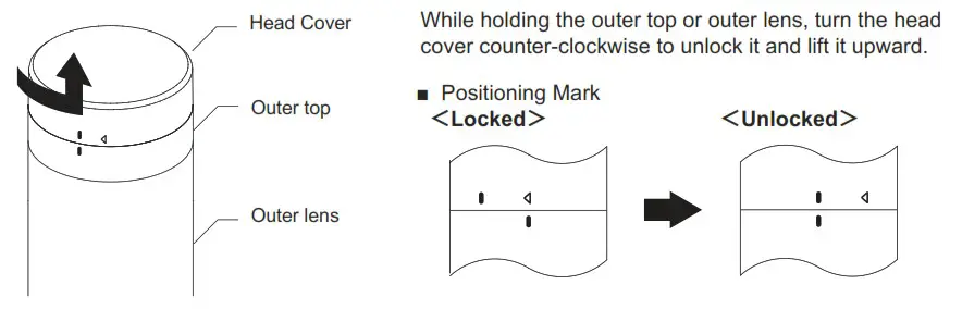
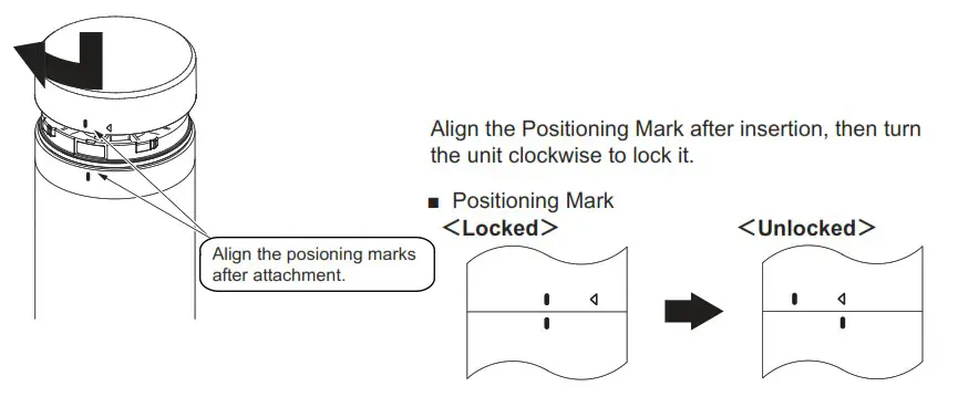
Atttach/detach the Head Cover
Follow the instruction below when attaching and detaching the buzzer unit.
![]() Warning
Warning
- Be sure that it is disconnected from the power source before working on it
![]() Caution
Caution
- Do not apply excessive torque or strong shock to each unit or body. Failure to comply will result in damage or malfunction.
- Do not touch the connector area or the inside of the body. Failure to comply will result in damage or malfunction.
- Be sure to lock buzzer unit securely when attaching. Failure to comply will result in damage or malfunction.
- The buzzer unit must be removed by holding the product body. Failure to comply will result in damage.
■ Detachment
■ Attachment
PATUITE Corporation G2J
| PATLITE Corporation * Head office | www.patlite.com/ |
| PATLITE (U.S.A.) Corporation | www.patlite.com/ |
| PATLITE Europe GmbH * Germany | www.patlite.eu/ |
| PATLITE (SINGAPORE) PTE LTD | www.patlite-ap.com/ |
| PATLITE (CHINA) Corporation | www.patlite.cn/ |
| PATLITE KOREA CO.,LTD. | www.patlite.co.kr/ |
| PATLITE TAIWAN CO., LTD. | www.patlite.tw/ |
| PATLITE (THAILAND) CO.,LTD. | www.patlite.co.th/ |
| PATLITE MEXICO S.A. de C.V. | www.patlite.com.mx/ |


