![]() Quick Start Guide
Quick Start Guide
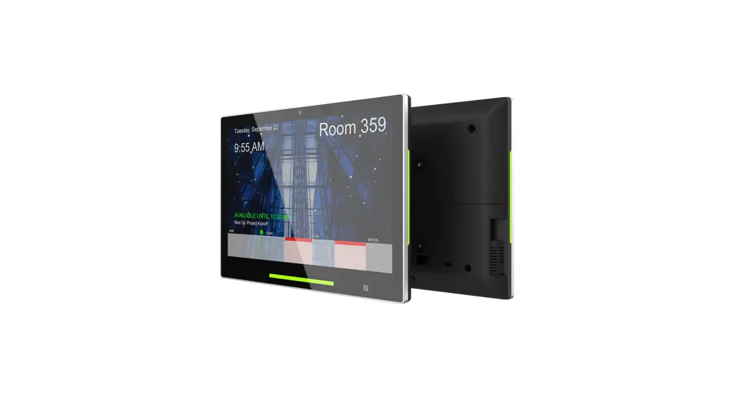
This quick guide will help you go through installaon quickly TD-1070
Touch Panel PC
 Support site Support site |
|
| https://www.qbictechnology.com/support | https://bit.ly/QBICQSG |
 QSG download link
Contents
Indication
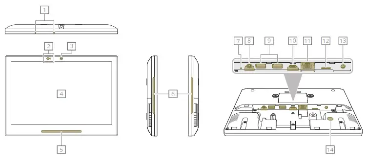
| 1. MIC 2. Optical Sensors 3. Camera 4. Display 5. Front LED 6. Side LED 7. Reset Button 8. Audio Jack | 9. USB 2.0 10. USB Type C for ADB 11. RJ45 / PoE+(36-57Vdc) 12. Micro SDHC 13. DC 12V 14. Kensington 15. Lock Slot |
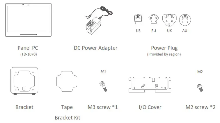
Installation
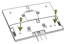
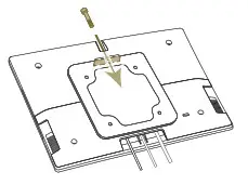
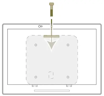
1. Cable connection
| STEP 1 Connect cables. Device will power on when DC/PoE+ is inserted. | STEP 2 Install I/O cover | STEP 3 Fix 2* M2 screws |
 | 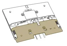 |  |
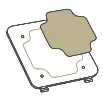
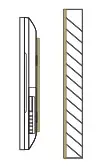
2. Tape Mount
| STEP 1 Attach tape on the back of bracket | STEP 2 Place the bracket on the back side of Panel PC | STEP 3 Fasten M3 screw*1 to secure the bracket and back cover | STEP 4 Fix the Panel PC on the surface using tape |
 |  |  |  |
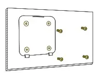
3. Surface Mount
| STEP 1 Install bracket on surface (screws not included) | STEP 2 Mount the Panel PC on the bracket | STEP 3 Fasten M3 screw*1 to secure the bracket and back cover |
 |  |  |
NOTICE:
◎ This Panel PC is also compatible with VESA mounting (75mm x 75mm). It is recommended to secure with M3 screw. The suggested length of the M3 screw is the thickness of VESA mounting bracket plus 8mm(Screw not included).
◎ Please ensure the mounting surface is clean and smooth before using the tape.
◎ M2 / M3 screw Torque<2 kgf-cm
◎ Installation height: <2M
CARE AND WARNING
◎ WARNING :
Changes or modifications to this unit not expressly approved by the party responsible for compliance will void the user’s authority to operate the equipment.
◎ NOTE : This equipment has been tested and found to comply with the limits for a Class B digital device, pursuant to Part 15 of the FCC Rules. These limits are designed to provide reasonable protection against harmful interference in a residential installation. This equipment generates, uses, and can radiate radio frequency energy, and if not installed and used in accordance with the instructions, may cause harmful interference to radio communications. However, there is no guarantee that interference will not occur in a particular installation. If this equipment does cause harmful interference to radio or television reception, which can be determined by turning the equipment off and on, the user is encouraged to try to correct the interference by one or more of the following measures :
- Reorient or relocate the receiving antenna.
- Increase the separation between the equipment and receiver.
- Connect the equipment into an outlet on a circuit different from that to which the receiver is connected.
- Consult the dealer or an experienced radio/panel PC technician for help.
This device complies with Part 15 of the FCC Rules. Operation is subject to the following two conditions :
- May not cause harmful interference.
- Must accept any interference received, including interference that may cause undesired operation.
![]() ◎ Correct disposal of this product :
◎ Correct disposal of this product :
This marking indicates that this product should not be disposed with other household wastes throughout the EU. To prevent possible harm to the environment or human health from uncontrolled waste disposal, recycle it responsibly to promote the sustainable reuse of material resources. To return your used device, use the return and collection systems or contact the retailer where the product was purchased. They can take this product for environmental safe recycling.
◎ The power consumption of the product in networked standby is 5.26W which all wired network ports are connected and all wireless network ports are activated.
◎ FCC & CE RF radiation Exposure Statement Caution : To maintain compliance with the FCC & CE`s RF exposure guidelines. Place the product at least 20cm from nearby persons.
◎ Replacement of a battery with an incorrect type that can defeat a safeguard
(for example, in the case of some lithium battery types);
Disposal of a battery into fire or a hot oven, or mechanically crushing or cutting of a battery, that can result in an explosion;
Leaving a battery in an extremely high temperature surrounding environment that can result in an explosion or the leakage of flammable liquid or gas;
A battery subjected to extremely low air pressure that may result in an explosion or the leakage of flammable liquid or gas
Removal
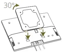
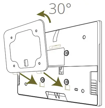
| STEP 1 Remove the top screw connecting the TD-1070 to the bracket | 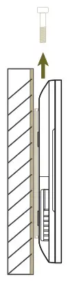 |
| STEP 2 With both hands supporting the top and bottom of the TD-1070 , carefully tilt the top section of TD-1070 downward 30° | 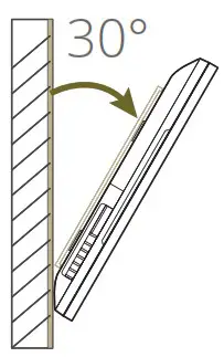 |
| STEP 3 Gently pull the TD-1070 down to remove from bracket | 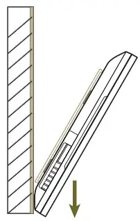 |
| STEP 4 Apply hot air gun to the tape beneath bracket until loose | 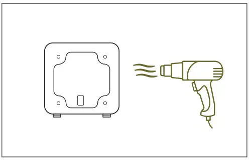 |
| STEP 5 Slowly pull the tape and the bracket downward off the surface | 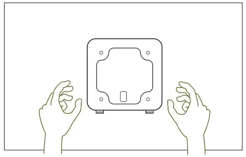 |
NOTE:
◎ DO NOT remove bracket or tape from surface forcefully. Excessive force during removal may lead to damaged surface.
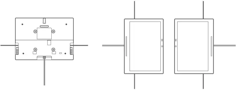
Variable Installation
Discrete Cable Outlets
The TD-1070 is designed for landscape or portrait installation with a discreet cable management system.
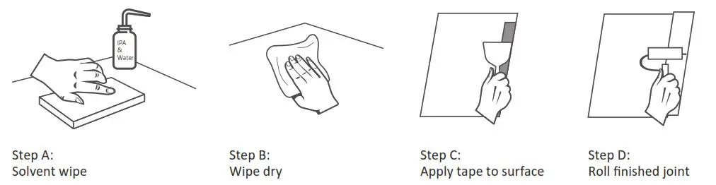
Surface Preparation for Tape Application
Most substrates are best prepared by cleaning with a 50:50 mixture of isopropyl alcohol (IPA) and water* prior to applying Tapes. There are exceptions!
◎ Exceptions to this general procedure that may require additional surface preparation include:
- Heavy Oils: A degreaser or solvent-based cleaner may be required to remove heavy oil or grease from a surface and should be followed by cleaning with IPA/water.
- Abrasion: Abrading a surface, followed by cleaning with IPA/water, can remove heavy dirt or oxidation and can increase surface area to improve adhesion.
- Porous Surfaces: Most porous and fibered materials such as wood, particleboard, concrete etc. need to be sealed to provide a unified surface.
- Unique Materials: Special surface preparation may be needed for glass and glass-like materials, copper and copper containing metals and plastics or rubber that contain components that migrate (e.g. plasticizers).
◎ General Procedure
- To obtain optimum adhesion, the bonding surfaces must be well unified, clean and dry.
Typical surface cleaning solvents are IPA/ water mixture (rubbing alcohol) or heptane. * (Steps A and B) - Bond strength is dependent upon the amount of adhesive-to- surface contact developed.
Firm application pressure develops better adhesive contact and helps improve bond strength. (Steps C and D) Generally, this means that the tape should experience at least 15 psi (100 kPa) in roll down or platen pressure. (Sources- page #4) - After application, the bond strength will increase as the adhesive flows onto the surface. At room temperature, approximately 50% of the ultimate strength will be achieved after 20 minutes, 90% after 24 hours and 100% after 72 hours. In some cases, bond strength can be increased and ultimate bond strength can be achieved more quickly by exposure of the bond to elevated temperatures (e.g. 150°F [66°C] for 1 hour).
NOTE : These cleaner solutions contain greater than 250 g/l of volatile organic compounds (VOC).
Please consult your local Air Quality Regulations to be sure the cleaner is compliant.
When using solvents, be sure to follow the manufacturer’s precautions and directions for use when handling such materials.
![]() CAUTION
CAUTION
Risk of explosion if the battery is replaced by an incorrect Wait one-half hour after switching off before handling parts
Power adapter information:
Model:WA-30P12R
INPUT:100-240V~50-60Hz 0.9A
OUTPUT:12.0V 2.5A 30.0W
NOTE : Operating Temperature: 0~ 40°C
![]() Qbic Technology Co.,Ltd.
Qbic Technology Co.,Ltd.
26F.-12,No.99.Sec.1, Xintai 5th Rd., Xizhi Dist., New Taipei City 221, Taiwan(R.O.C)
Tel: 886-2-2697-2000 FAX:886-2-2697-2868


