![]() 8595_ins_hum_duct_out_592_5_20
8595_ins_hum_duct_out_592_5_20
Duct or Outside Air Humidity Transmitter Units
with AD592 or LM334 Semiconductor Temperature Sensor
Installation and Operating Instructions
rev. 09/20/21
Overview
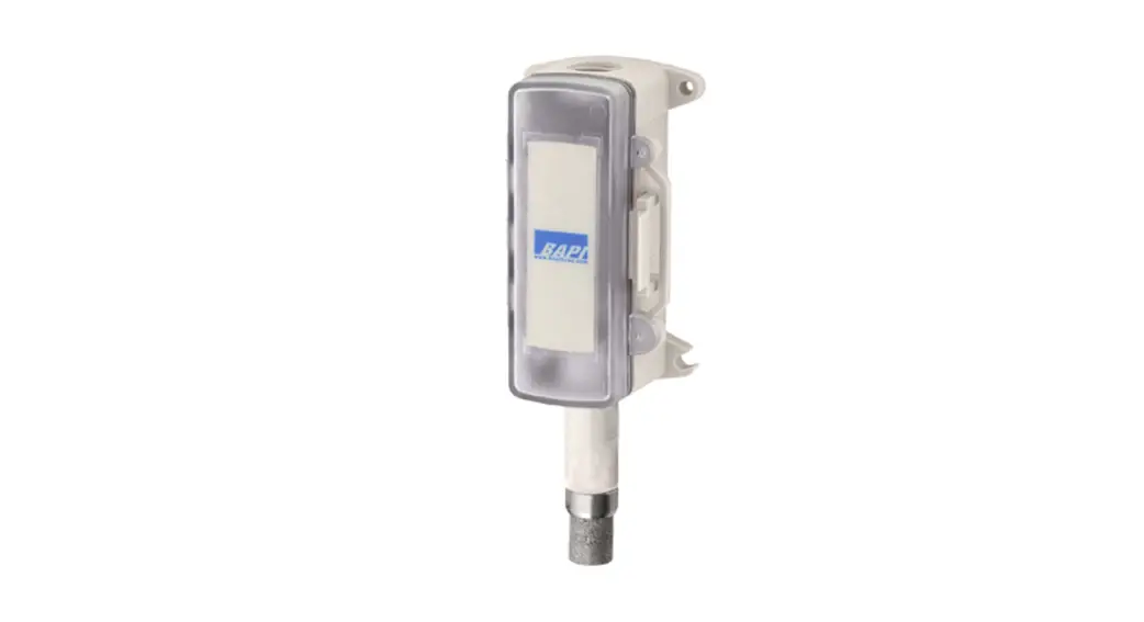
The duct and outside air humidity transmitters with a solid state AD592 or LM334 semiconductor temperature sensor come with ±2% or ±3%RH accuracy and can be ordered with a Weatherproof (WP), BAPI-Box (BB), or BAPI-Box 2 (BB2) Enclosure. The humidity transmitter is available with either 4 to 20 mA, 0 to 5V, 0 to 10V, or 2 to 10V output.
Duct Unit Mounting
Fig. 1: Duct Humidity in a Weatherproof (WP) Enclosure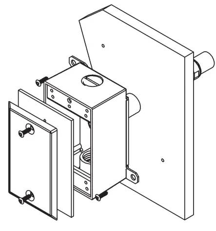 Fig. 2: Duct Humidity in a BAPI-Box (BB) Enclosure
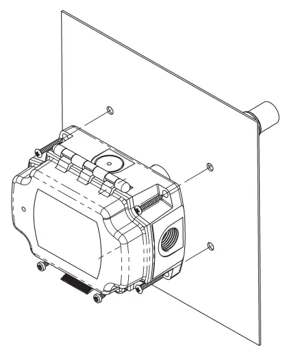
Fig. 3: Duct Humidity in a BAPI-Box 2 (BB2) Enclosure
Mount at least 3 duct diameters from humidifiers in the center of the duct wall. Drill a 1” hole for the probe in the duct and use two number 8 sheet metal screws to attach the sensor to the duct. Center the probe in its mounting hole. Be sure that the foam seals the hole, do not overtighten the screws.
Outside Air Mounting
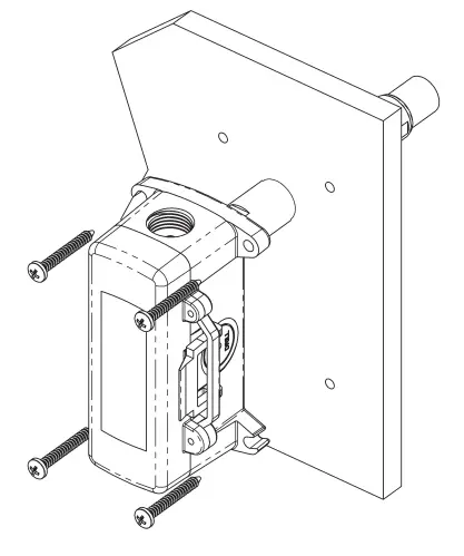
Fig. 4: Outside Humidity in a Weatherproof (WP) Enclosure
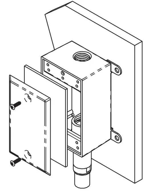
Fig. 5: Outside Humidity in a BAPI-Box (BB) Enclosure
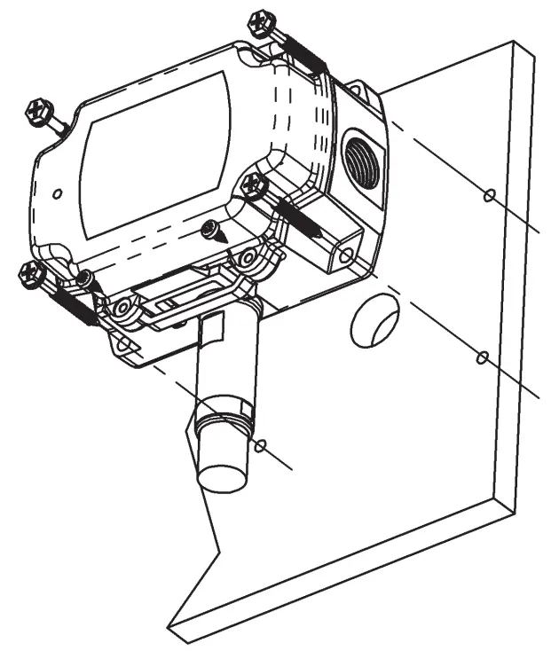
Fig. 6: Outside Humidity in a BAPI-Box 2 (BB2) Enclosure
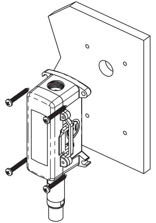
Mount in a permanently shaded area away from windows and doors. Do not mount in direct sunlight. Mount with the sensor probe pointed down. Drill a hole large enough for your sensor cable through your mounting surface. Mount the unit to the surface with the wiring knock out centered over the wiring hole. Pull the wiring into the unit and terminate using sealant-filled connectors. Best practice is to seal the wiring hole with caulk after the wiring is installed. Be sure that the foam on the back of the unit makes a good weather-tight seal.
Wiring and Termination
BAPI recommends using twisted pairs of at least 22AWG and sealant-filled connectors for all wire connections. Larger gauge wire may be required for long runs. All wiring must comply with the National Electric Code (NEC) and local codes. Do NOT run this device’s wiring in the same conduit as AC power wiring of NEC class 1, NEC class 2, NEC class 3, or with wiring used to supply highly inductive loads such as motors, contactors, and relays. BAPI’s tests show that fluctuating and inaccurate signal levels are possible when AC power wiring is present in the same conduit as the signal lines. If you are experiencing any of these difficulties, please contact your BAPI representative![]() BAPI recommends wiring the product with power disconnected. Proper supply voltage, polarity, and wiring connections are important to a successful installation. Not observing these recommendations may damage the product and will void the warranty.
BAPI recommends wiring the product with power disconnected. Proper supply voltage, polarity, and wiring connections are important to a successful installation. Not observing these recommendations may damage the product and will void the warranty.
| Table 1: Humidty Transmitter with 4 to 20mA Output | ||
| Wire Color | Purpose | Note |
| White | Not Used | Not Used (Cap Wires) |
| Black | Humidity Output | 4 to 20 mA, To Analog Input of Controller |
| Red | Power | 10 to 35VDC |
| Table 2: HumidityTransmitter with 0 to 5VDC Output | ||
| Wire Color | Purpose | Note |
| White | Humidity Output | 0 to 5VDC, To Analog Input of Controller |
| Black | GND (Common) | Ground for Power and Humidity Output |
| Red | Power | 10 to 35VDC or 12 to 27 VAC |
| Table 3: Humidity Transmitter with 0 to 10VDC Output | ||
| Wire Color | Purpose | Note |
| Green | Humidity Output | 0 to 10VDC, To Analog Input of Controller |
| Black | GND (Common) | Ground for Power and Humidity Output |
| Red | Power | 15 to 35VDC or 15 to 27VAC |
| Table 4: Humidity Transmitter with 2 to 10VDC Output | ||
| Wire Color | Purpose | Note |
| Brown | Humidity Output | 2 to 10VDC, To Analog Input of Controller |
| Black | GND (Common) | Ground for Power and Humidity Output |
| Red | Power | 15 to 35VDC or 15 to 27VAC |
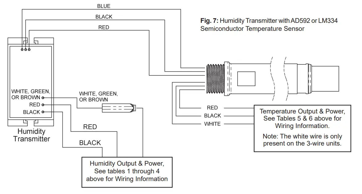
| Table 5: Temperature Sensor Termination Table | ||
| AD592 or LM334 2-Wire Semiconductor- From Probe | ||
| Wire Color | Purpose | Note |
| Red | Power | Connect to +5 to +30 VDC |
| Black | Temperature Output | Connect to Controller’s Analog Input* |
*Note – For 2-wire 592 or 334, a 0.1% resistor must be installed between the black output wire and the controller’s ground.
| Table 6: Temperature Sensor Termination Table | ||
| AD592-10K or LM334-10K 3-Wire Semiconductor – From Probe | ||
| Wire Color | Purpose | Note |
| Red | Power | Connect to +5 to +30 VDC |
| Black | GND (Common) | Ground for Temperature Output |
| White | Temperature Output | Connect to Controller’s Analog Input |
Temperature Sensor Offset
This is how BAPI calculates the offset value provided on the equipment label for the AD592 or LM334 Sensor:
Therm Reading_______
The actual temperature reading according to a thermometer that is NIST certified traceable
Sensor Reading ______
The temperature reading is according to the sensor, using the output in either uA or mV.
Offset_______
The difference between Thermometer Reading and the Sensor Reading
To correct the sensor reading, simply add the offset value to the sensor reading so that it equals the thermometer reading.
e.g. Therm Reading: 74.6 Sensor Reading: 73.0 Offset: +1.6
Correction: Add (+1.6) °F to the sensor at the controller for an accurate reading: 73 + 1.6 = 74.6°F
Filter Care
A sintered filter protects the humidity sensor from airborne particles and may need periodic cleaning. To do this, gently unscrew the filter from the probe. Rinse the filter in warm soapy water until clean. A nylon brush may be used if necessary. Gently replace the filter by screwing it back into the probe. The filter should screw all the way into the probe. Hand tightens only.
Specifications
Supply Power:
Units with RH Output of 4 to 20mA or 0 to 5VDC 10 to 35VDC, 22mA max
Units with RH Output of 0 to 5VDC: 12 to 27VAC, 0.53VA max
Units with RH Output of 0 to 10VDC or 2 to 10VDC 15 to 35VDC, 6mA max or 15 to 27VAC, 0.14VA max
Sensor: Factory corrected @17 RH points (10 to 90% RH)
Humidity……………. Capacitive Polymer
RH Accuracy …….. ±2% @ 73°F (23°C) from 10 to 90%
Drift ……………….. 0.5% per year
Response time…… < 5 seconds in moving air
RH Linearity ………. Negligible, factory corrected linier from 10 to 90%
RH Hysteresis ….. Factory corrected to <1%
Humidity Filter: 80 micron sintered stainless steel filter Calibrated Accuracy: Calibration @17 RH points, (10% to 90%)
RH 2% ……………… 2% from 10 to 90% @ 73°F (23°C), Non-condensing
RH 3% ……………… 3% from 10 to 95% @ 73°F (23°C), Non-condensing
Humidity Transmitter Output (0 to 100%RH)
H200, H300 ………. 4 to 20mA or 0 to 5VDC
H210, H310 ………. 0 to 10VDC
H212, H312 ………. 2 to 10VDC
Humidity Output Impedance:
Current …………….. 700W @ 24VDC, Voltage drop is 10VDC
Voltage …………….. 10KW
Probe Length:
Duct ……………….. 5.3” (13.5cm) Duct Insertion, 1” dia.
Outside Air ………… 2.4” (6.1cm) Below Enclosure, 1” dia.
Dimensions: W x H x D
Weatherproof (WP) 2.75” x 4.5” x 2.2”, (70 x 114 x 55 mm)
BAPI-Box (BB) ….. 4.15” x 5” x 2.5”, (105.4 x 127 x 63.5mm)
BAPI-Box 2 (BB2) 4.9” x 2.8” x 2.35”, (124.8 x 71.6 x 59.7mm)
Termination: Open wire
Crimp :18 to 26 AWG, Sealant Filled Connector (BA/SFC1000-x00)
Wire Nut: 26 to 16 AWG, Sealant Filled Wire Nut (BA/SFC2000-x00)
Enclosure Material and Rating:
Weatherproof (WP) Cast Aluminum, NEMA-3R
BAPI-Box (BB) …… Polycarbonate, UV resistant, NEMA-4, IP66, UL94V-0
BAPI-Box 2 (BB2) . Polycarbonate, UV resistant, NEMA-4, IP66, UL94V-0
Environ. Ambient Range: -40º to 158ºF (-40º to 70ºC) • 0 to 100%RH
Approvals: RoHS
AD592 SOLID STATE SEMICONDUCTOR SPECS
Temperature Sensor Output
Voltage……………..2.83 to 3.1 VDC = 50º to 100°F
Current……………..0.283 to .31 mA = 50º to 100ºF
Temp. Sensitivity:
2 wire ……………….1uA/ºC (0.556uA/ºF)
3 wire ……………….10mV/ºC, (5.556mV/ºF
Reference Point: 25ºC (77ºF)
AD592 ………………298.20uA
AD592-10K ……….2.982VDC
Voltage Supply: 5VDC to 30VDC
Temp. Range: -25 to 105ºC (-13 to 221ºF)
Accuracy: With Factory offset to 0.1ºC (0.18ºF)
Raw AD592, ±3.3ºF (1.8ºC) from -13 to 221ºF
Linearity:
±0.15ºC max from 0 to 70ºC
(±0.27ºF max from 32 to 158ºF)
Repeatability: ± 0.1ºC (±0.18ºF)
Response Time: 10 seconds at the 63% step
LM334 SOLID STATE SEMICONDUCTOR SPECS
Temperature Sensor Output
Voltage……………..2.83 to 3.1 VDC = 50º to 100°F
Current……………..0.283 to .31 mA = 50º to 100ºF
Temp. Sensitivity: .
2 wire ……………….1uA/ºC (0.556uA/ºF)
3 wire ……………….10mV/ºC, (5.556mV/ºF)
Reference Point: 25ºC (77ºF)
LM334………………298.20uA
LM334-10K ……….2.982VDC
Voltage Supply: 5VDC to 30VDC
Temp. Range:
Nominal, 0 to 70ºC (32 to 158ºF), 100ºC max
Accuracy: With Factory offset to 0.1ºC (0.18ºF)
Raw LM334, ±10.8ºF (6ºC) from 32 to 212ºF
Linearity: ±0.15ºC max from 0 to 70ºC
Repeatability: ±0.1ºC (±0.18ºF)
Response Time: 10 seconds at the 63% step
Humidity Diagnostics
Possible Problems:
Unit will not operate
Humidity output is at its maximum or minimum value
Humidity reading in the controller’s software appears to be off by more than the specified accuracy
| Output | Humidity Formula |
| 4 to 20mA | %RH =(mA-4)/0.16 |
| 0 to 5VDC | %RH = V/0.05 |
| 0 to 10VDC | %RH = V/0.1 |
| 2 to 10VDC | %RH = (V-2)/0.08 |
Possible Solutions:
- Check for proper supply power. (See wiring diagram and power specs.)
- Make sure the humidity sensor is wired properly.
- If the output is at its maximum value, verify the humidity in the environment with a reference sensor. If the humidity drops to 5% or below in the environment, the output will go to the maximum value.
- Check all software parameters
- Determine if the sensor is exposed to an external air source different from the measured environment, such as air infiltration through the wiring conduit.
- Check the Humidity transmitter output against a calibrated reference such as a 2% accurate hygrometer. Measure the humidity at the sensor’s location using the reference meter, then calculate the humidity transmitter output using the humidity formula at left. Compare the calculated output to the actual humidity transmitter output (see the wiring diagram for the humidity transmitter output wire colors). If the calculated output differs from the humidity transmitter output by more than 4% to 5%, contact BAPI technical support.
Temperature Diagnostics
The AD592 and LM334 semiconductor sensors transform temperature into current. The output changes 1 micro-amp for every degree Celsius (0.56 micro-amp per degree Fahrenheit). Since most meters used by field technicians cannot accurately measure currents this low, BAPI recommends that a 10KΩ 0.1% resistor be placed between the sensor output and ground. The 10KΩ resistor changes the sensor output current into a voltage that varies by 0.01 volts per degree Celsius (0.0056 volts per degree Fahrenheit). This is in the range of most meters used by field technicians. Resistors with other tolerances can be used, but there will be greater temperature errors (see 10KΩ Error Table).
BAPI offers AD592 and LM334 sensors with a built-in 10KΩ 0.1% resistor from the output to ground, or without the sensor (in which case the customer must supply and wire their own 10KΩ resistor from the output to ground). Sensors with built-in resistors have three wires – red, black, and white. Sensors without resistors have two wires – red and black.
If the humidity transmitter is set up for 4 to 20mA output, there is no signal ground at the sensor to use as a reference for the voltage measurements for the two-wire AD592 or LM334 temp sensors. The ground pin at a local power plug may be at the correct potential or you may have to pull a temporary ground wire from the controller to make the measurements. There will be ground in the 3-wire AD592 or LM334 sensors.
- Check for proper supply voltage from the sensor’s red power lead (+5 to +30 VDC) to the controller’s ground.
- For 2-wire units, make sure that there is a 10KΩ 0.1% resistor from the sensor’s black wire to the controller’s ground.
- To verify sensor operation, measure the mV from the 2-wire sensor’s black wire to the controller’s ground, or from the 3-wire sensor’s white wire to the black wire. Compare the voltage measurement to the voltage listed in the AD592 or LM334 Output Table. Note: Be sure to include the error from the10KΩ Error Table.
- If the sensor reads within 0.05 VDC of the table, then it is operating properly. In this case, verify that the controller is operating correctly. If the sensor is off by more than 0.05 VDC, call BAPI technical support.
- Determine if the sensor is exposed to an external source different from the intended room environment.
| 10KΩ Resistor Error Table | |
| 10KΩ Resistor Tolerance | Temperature Inaccuracy |
| 0.10% | ±3.3°F/1.8°C |
| 1% | ±8.3°F/4.6°C |
| 5% | ±30.7°F/17.1°C |
| AD592 or LM334 Output Table | |||
| Temperature | 592 or 334 Semiconductor | ||
| °F | °C | Output Current uA | Output Voltage across 10KΩ |
| 50 | 10 | 283.2 | 2.832 |
| 60 | 15.56 | 288.8 | 2.888 |
| 62 | 16.67 | 289.9 | 2.899 |
| 64 | 17.78 | 291 | 2.91 |
| 66 | 18.89 | 292.1 | 2.921 |
| 68 | 20 | 293.2 | 2.932 |
| 70 | 21.11 | 294.3 | 2.943 |
| 72 | 22.22 | 295.4 | 2.954 |
| 74 | 23.33 | 296.5 | 2.965 |
| 76 | 24.44 | 297.6 | 2.976 |
| 77 | 25 | 298.2 | 2.982 |
| 78 | 25.56 | 298.8 | 2.988 |
| 80 | 26.67 | 299.9 | 2.999 |
| 82 | 27.78 | 301 | 3.01 |
| 84 | 28.89 | 302.1 | 3.021 |
| 86 | 30 | 303.2 | 3.032 |
| 88 | 31.11 | 304.3 | 3.043 |
| 90 | 32.22 | 305.4 | 3.054 |
| 100 | 37.78 | 311 | 3.11 |
Building Automation Products, Inc., 750 North Royal Avenue, Gays Mills, WI 54631 USA
Tel:+1-608-735-4800 • Fax+1-608-735-4804 • E-mail:[email protected] • Web:www.bapihvac.com


