GEARSTONE HC1 Foldable Indoor Rowing Machine
IMPORTANT SAFETY INFORMATION
We thank you for choosing our product. To ensure your safety and health, please use this equipment correctly. It is important to read this entire manual before assembling and using the equipment. Safe and effective use can only be assured if the equipment is assembled, maintained, and used properly. It is your responsibility to ensure that all users of the equipment are informed of all warnings and precautions.
- Before starting any exercise program you should consult your physician to determine if you have any medical or physical conditions that could put your health and safety at risk or prevent you from using the equipment properly. Your physician’s advice is essential if you are taking any medication that may affect your heart rate, blood pressure, or cholesterol level.
- Be aware of your body’s signals. Incorrect or excessive exercise can damage your health. Stop exercising if you experience any of the following symptoms: pain, tightness in your chest, irregular heartbeat, shortness of breath, lightheadedness, dizziness, or feelings of nausea. If you do experience any of these conditions, you should consult your physician before continuing with your exercise program.
- Keep children and pets away from the equipment. The equipment is designed for adult use only.
- Use the equipment on a solid, flat level surface with a protective cover for your floor or carpet. To ensure safety, the equipment should have at least 2 feet of free space all around it.
- Ensure that all nuts and bolts are securely tightened before using the equipment. The safety of the equipment can only be maintained if it is regularly examined for damage and/or wear and tear.
- lt is recommended that you lubricate all moving parts on a monthly basis.
- Always use the equipment as indicated. If you find any defective components while assembling or checking the equipment, or if you hear any unusual noises coming from the equipment during exercise, stop using the equipment immediately and don’t use the equipment until the problem has been rectified.
- Wear suitable clothing while using the equipment. Avoid wearing loose clothing that may become entangled in the equipment.
- Do not place fingers or objects into the moving parts of the equipment.
- The maximum weight capacity of this unit is 120kg.
- This equipment is not suitable for therapeutic use.
- Move with caution when lifting and moving the equipment. Always use proper lifting technique and seek assistance if necessary.
- Your product is intended for use in cool, dry conditions. You should avoid storage in extreme cold, hot, or damp areas as this may lead to corrosion and other related problems.
- This equipment is designed for indoor use only! It is not intended for commercial use!
 WARNING: This product can expose you to one or more chemicals known to the State of California to cause cancer and birth defects or reproductive harm.
EXPLODED DRAWING
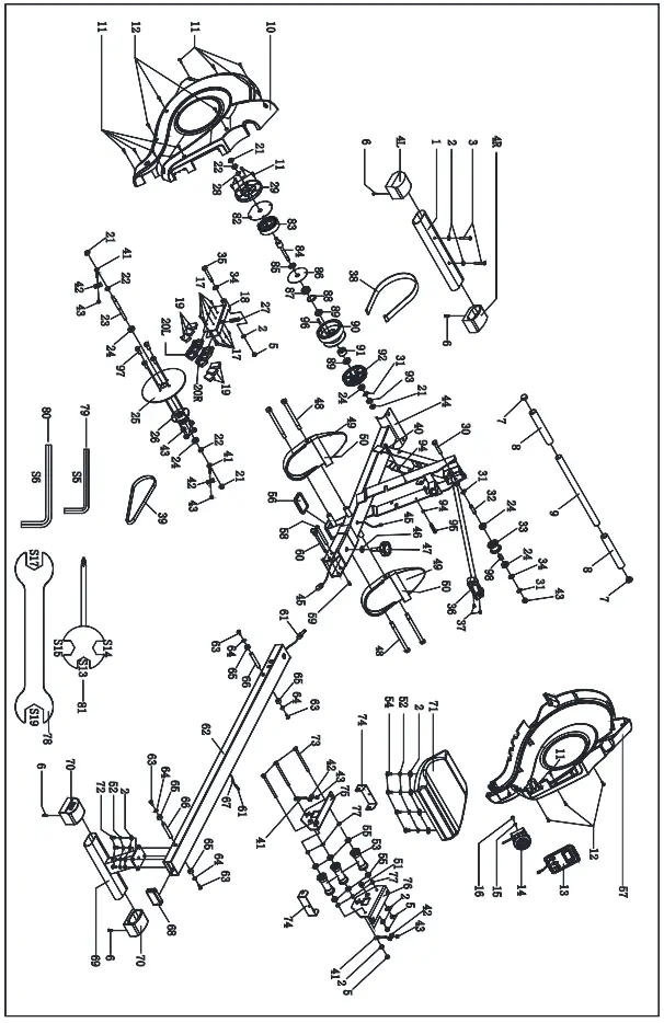
PARTS LIST
| No. | Description | Spec. | QT V |
| Front stabilizer | |||
| 2 | Washer | d8*<P1 6*1.5 | 14 |
| 3 | Screw | M8*55*20*S6 | 2 |
| 4 | End cap | 2 | |
| 5 | Nut | M8*H7 5*8 13 | 4 |
| 6 | Screw | ST4.2*25*¢>1 0.5 | 4 |
| 7 | End cap | ¢>28*16 | 2 |
| 8 | Foam grip | ¢>26*3*208 | 2 |
| 9 | Handlebar | cp28*1 . 5*440 | |
| 10 | Left chain cover | 666*550*83 | 1 |
| 11 | Screw | ST4.2*19*<P8 | 13 |
| 12 | Screw | ST4.2*16*<P8 | 6 |
| 13 | Computer | ||
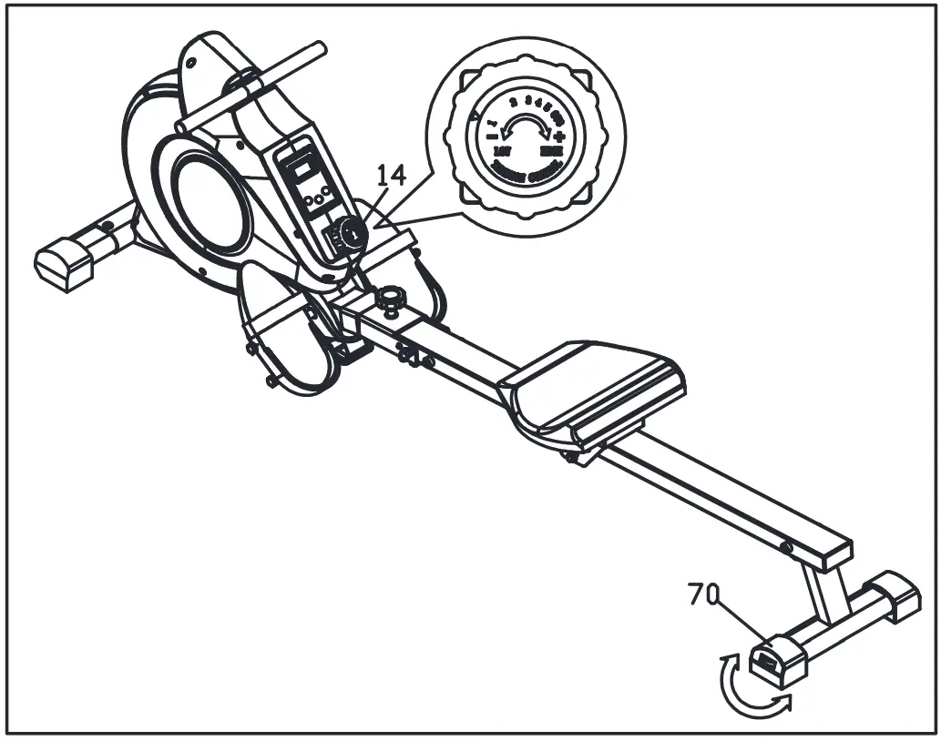
| 14 | Tension control | ¢>1.5*650*42 | |
| 15 | Washer | d5*¢>20*1.5 | |
| 16 | Screw | M5*8*¢>8 | |
| 17 | Screw | ST3*10*<P5.6 | 10 |
| 18 | Magnetic plate | ||
| 19 | Magnet | 39*24.5*10 | 6 |
| 20L/R | Magnet location grid | 112.4*60.6*10.2 | 2 |
| 21 | Nut | M10*1*HB*S15 | 4 |
| 22 | Nut | M10*1*H5*S17 | 3 |
| 23 | Axle | <P12 * 1 3 2 *M10*1.0*24 | |
| 24 | Bearing | 6000 | 5 |
| 25 | Aluminum wheel | . 14 O* <P200 *<P3 0 | |
| 26 | Shaft sleeve | ¢>33*45*39*4-M6*¢>60 | |
| 27 | Spring | ¢>1.. 2 *¢> 15*54*N10 | |
| 28 | Washer | d10*<P2 0*1.5 | |
| 29 | Cover | ¢>118 . 5*11.8 | |
| 30 | Bolt | ||
| 31 | Circlip for shaft | d10 | 3 |
| 32 | Axle | <P10*40*<P6 . 1 | |
| 33 | Pulley | ¢>45*35 | |
| 34 | Wave washer | d10*¢>13 .5 *0.3 | 2 |
| 35 | Bolt | <P10 *72*M8*12.5*S17 | |
| 36 | Handlebar seat | 106*40*31 | |
| 37 | Screw | M5*10*<P10 | 2 |
| 38 | Mesh belt | t1 .5*22*2150 | |
| 39 | Belt | ||
| 40 | Bolt | M6*55*S10 | |
| 41 | Adjusting screw | M6*40*<P10*2 . 5 | 4 |
| 42 | Adjusting U seat | 30*10*1.5 | 4 |
| 43 | Nut | M6*H6*S10 | 9 |
| 44 | Main frame | ||
| 45 | Trunk wire | Length 800 | |
| 46 | Washer | d12*<P24*2 | |
| 47 | Knob | M12*30*¢>14*15*¢>56 | |
| 48 | Bolt | M12 * <D 1 2.5*160*23*S19 | 4 |
| 49 | Pedal L/R | 320*140*55 | 2 |
| 50 | Pedal strap | 585*50 | 2 |
| 51 | Magnet | <D 15*7 | |
| 52 | Spring washer | dB | 8 |
| 53 | Wheel | <D 40*92 | 3 |
| 54 | Bolt | M8*16*S6 | 4 |
| 55 | Bearing | 608Z | 6 |
| 56 | Rubber pad | 84.5*49.5*9.7 | |
| 57 | Right chain cover | 666*550*83 | |
| 58 | Bolt | <P1 0*95*M6*25 | |
| 59 | Screw | M6*16*S5 | |
| 60 | Pull pin | ¢>8*100*105 | |
| 61 | Sensor wire | ||
| 62 | Sliding rail | ||
| 63 | Screw | M6*16*<P12 | 4 |
| 64 | Washer | d6*<P12 *1 | 4 |
| 65 | Limit mat | (!)33*(!)8*13 | 4 |
| 66 | Limit axle | <P1 2*80*M6 | 2 |
| 67 | Grommet | ¢>16 | |
| 68 | End cap | J80*40*18 | |
| 69 | Rear support | ||
| 70 | End cap | PT80*40*71 .5*90*6 5 | 2 |
| 71 | Saddle | DDPU986 | |
| 72 | Screw | M8*20*S6 | 4 |
| 73 | Bolt | M8*125*15*S14 | 3 |
| 74 | U shape baffle | t2.0*183*38 | 2 |
| 75 | Left seat supporting board | t4 .0*18 5*157 | |
| 76 | Right seat supporting board | ||
| 77 | Bushing | d8*<P1 5*4 | 6 |
| 78 | Spanner | S17-19 | |
| 79 | Allen wrench | S5 | |
| 80 | Allen wrench | S6 | |
| 81 | Spanner | S13-14-15 | |
| 82 | PC Sheet | <D 111*<P16 * 0 5 | |
| 83 | Spiral spring | t0.5*22*5080 | |
| 84 | Axle | <D 10 *130*M10*1.0 | |
| 85 | Wave washer | d10*cD15 . 5 *0.3 | |
| 86 | PC Sheet | <D 89.5*(!)16 *0.5 | |
| 87 | Bearing | 6300-2RS | |
| 88 | Circlip For Hole | d35 | |
| 89 | Bearing | 16003 | 2 |
| 90 | Braid wheel | <D 11 2*67 5 | |
| 91 | Bearing | <!i 3 5*d17*16 | |
| 92 | Belt pulley | ||
| 93 | Nut | M10*1*H3*S14 | |
| 94 | Nut | M6*H5*S10 | 2 |
| 95 | Nut | M6*45*S10 | |
| 96 | Axle | <!>5*43 | |
| 97 | Blot | M6*16*S10 | 4 |
| 98 | Bushing | ¢ 15*<!>10.2*19 | |
ASSEMBLY INSTRUCTIONS
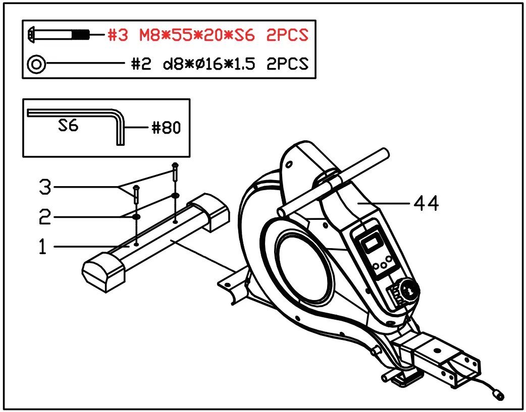
STEP 1:
Attach the Front Stabilizer (No.1) to the Main Frame (No.44) using 2 Screws(No.3) and 2 Washers (No.2). Tighten and secure with Allen Wrench (No.80).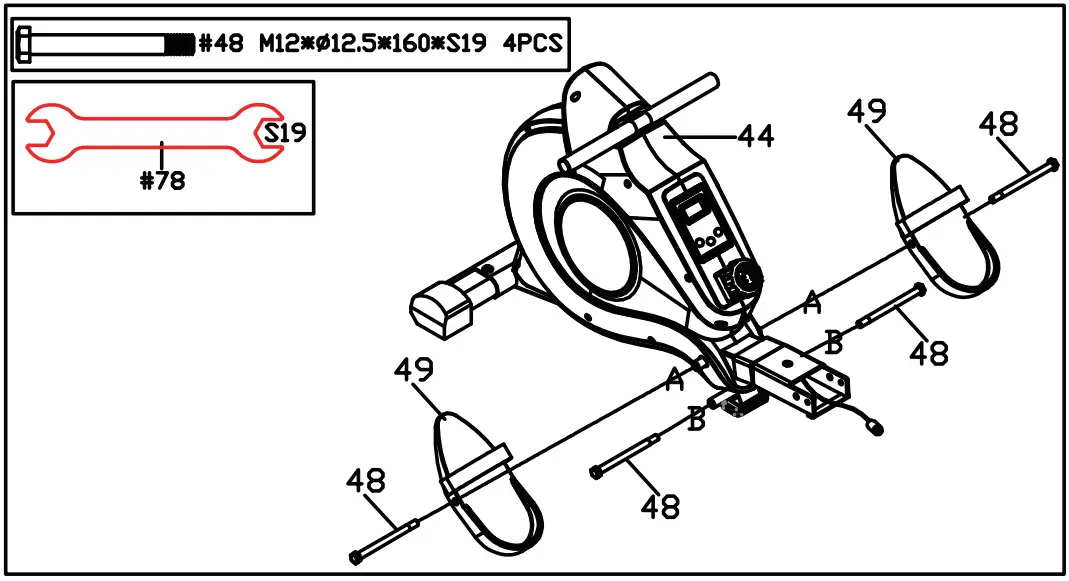
STEP 2:
Fix the2 Bolts (No.48) into the bottom hole in position B of Main Frame (No.44)with Spanner (No.78).
Attach the 2 Bolts (No.48) into the upper hole in position A of the Main Frame (No.44) through the Pedals (No.49) and tighten with Spanner (No.78).
NOTE: The Pedals (No.49) should rest on the Bolts (No.48)that are in position B.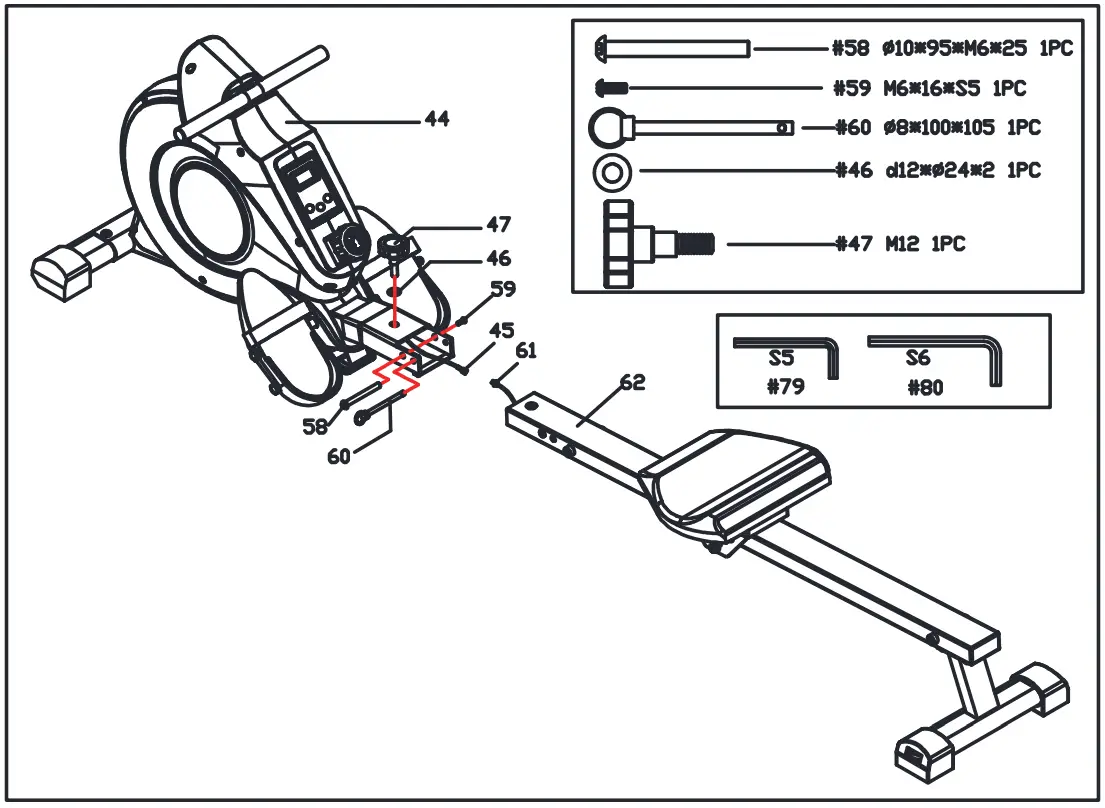
STEP 3:
Insert the Saddle (No.71 )into the Sliding Rail (No.62).
Insert the Limit Axle (No.66) into the hole on the back of the Sliding Rail (No.62). Attach the Limit Mat (No.65) onto the Limit Axle (No.66) using 1 Screw (No.63) and 1 Washer (No.64) then tighten with Spanner (No.81 ).
STEP 4:
Attach the Sliding Rail (No.62) onto the Rear Support (No.69) using 4 Screws (No.72), 4 Spring Washers (No.52), and 4 Washers (No.2). Tighten and secure with Allen Wrench (No.80).
STEP 5:
Connect Trunk Wire 1 (No.45) with the Sensor Wire (No.61 ).
Attach the Sliding Rail (No.62) to Main Frame (No.44) using 1 Bolt (No.58) and 1 Screw (No.59). Tighten and secure with Allen Wrench (No. 79) and Allen Wrench (No. 80).
Next, fix the top of the Sliding Rail (No. 62) to the Main Frame (No. 44) using 1 Knob (No.4 7) and 1 Washer (No.46) then insert the Pull Pin (No.60).
The assembly is complete!
ADJUSTMENT GUIDE
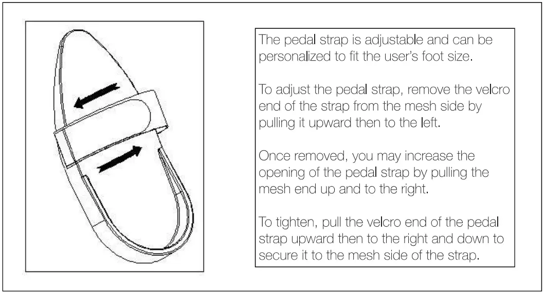
PEDAL ADJUSTMENT
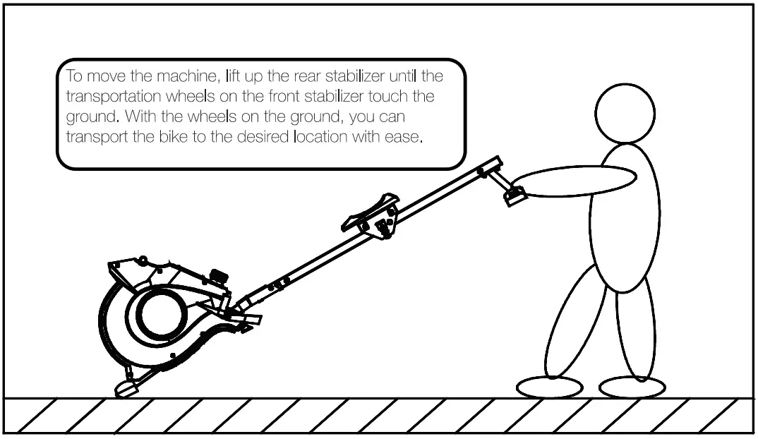
MOVING THE MACHINE
ADJUSTING THE BALANCE
Adjust the End Caps (No. 70) on the rear stabilizer of the machine if the machine is unbalanced during use.
ADJUSTING THE RESISTANCE
Rotate the Tension Control Knob (No.14)clockwise to increase the level of resistance. Rotate the tension control counter-clockwise to decrease the level of resistance.
Tension levels are set at Level 1 being the lowest and Level 8 being the highest.
CAUTION!
Moving parts, such as the seat, can crush and cut. Keep hands clear of the sliding rail during use!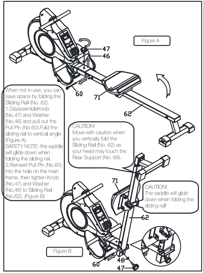
EXERCISE METER
Our computerized display console on the Rowing Machine allows the user to tailor a personalized workout by monitoring their progress. During a workout, the display console will alternately and repeatedly display your Time, Count, Calories Burned, Total Count, and Scan (all of the above). With our easy-to-use console, the user can efficiently track their fitness improvements from one workout to the next.
FUNCTION KEY:
- MODE: To select your specification mode and/or turn on display console.
- SET: To set a value of Time or Calories (when not in Scan mode).
- RESET: Press to reset Time or Calories.


FUNCTIONS AND OPERATIONS:
- SCAN: Press MODE button until SCAN appears. The display will rotate through the fivefunctions in the following order: TIME, COUNT, CALORIES, and TOTAL COUNT. Each display will be held for 4 seconds.
- TIME: Counts the total time elapsed during your current workout.
- COUNT: Counts the number of rowing strokes from your current workout.
- CAL: Counts the total calories burned from current workout.
- TOTAL COUNT: Counts the total amount of strokes from the first use.
- AUTO ON/OFF & AUTO START/STOP:
The power will turn off automatically once there’s no signal for 4 minutes. The meter will reactivate once the machine is put into motion or when a meter key is pressed.
SPECIFICATIONS
|
FUNCTIONS | SCAN | Every 6 seconds |
| TIME | 0:00~99:59(Minute:Second) | |
| COUNT | 0~9999 Count | |
| CALORIES | 0.0~999.9~9999 Kcal | |
| TOTAL COUNT | 0~9999 hundred count | |
| BATTERY TYPE | (2)Two AAA or UM-4 | |
| OPERATING TEMPERATURE | 0° C ~40 ° C | |
| STORAGE TEMPERATURE | -10° C ~ 60 ° C | |