![]() E7 3-4 Inch Elima Matic Bolted Metal
E7 3-4 Inch Elima Matic Bolted Metal
Owner’s Manual
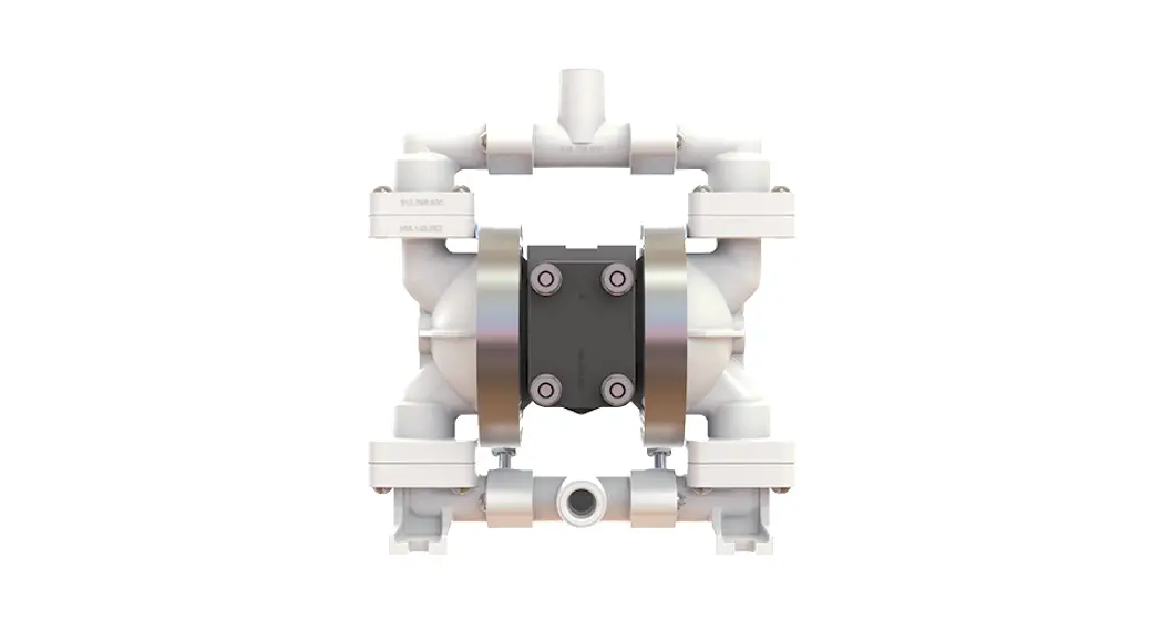
3/4″ Elima-Matic Bolted Metal
with Metal and Plastic Center Sections
E7 Metal Pumps
• Aluminum
Safety Information
IMPORTANT![]() Read the safety warnings and instructions in this manual before pump installation and start-up. Failure to comply with the recommendations stated in this manual could damage the pump and void factory warranty.
Read the safety warnings and instructions in this manual before pump installation and start-up. Failure to comply with the recommendations stated in this manual could damage the pump and void factory warranty.![]() When the pump is used for materials that tend to settle out or solidify, the pump should be flushed after each use to prevent damage. In freezing temperatures the pump should be completely drained between uses.
When the pump is used for materials that tend to settle out or solidify, the pump should be flushed after each use to prevent damage. In freezing temperatures the pump should be completely drained between uses.![]() CAUTION
CAUTION![]() Before pump operation, inspect all fasteners for loosening caused by gasket creep. Retighten loose fasteners to prevent leakage. Follow recommended torques stated in this manual.
Before pump operation, inspect all fasteners for loosening caused by gasket creep. Retighten loose fasteners to prevent leakage. Follow recommended torques stated in this manual.![]() Plastic pumps and plastic components are not UV stabilized. Ultraviolet radiation can damage these parts and negatively affect material properties. Do not expose to UV light for extended periods of time.
Plastic pumps and plastic components are not UV stabilized. Ultraviolet radiation can damage these parts and negatively affect material properties. Do not expose to UV light for extended periods of time.![]() WARNING
WARNING
Pump not designed, tested or certified to be powered by compressed natural gas. Powering the pump with natural gas will void the warranty.![]() WARNING
WARNING
The use of non-OEM replacement parts will void (or negate) agency certifications, including CE, ATEX, CSA, 3A and EC1935 compliance (Food Contact Materials). Warren Rupp, Inc. cannot ensure nor warrant non-OEM parts to meet the stringent requirements of the certifying agencies.
![]() WARNING
WARNING![]() When used for toxic or aggressive fluids, the pump should always be flushed clean prior to disassembly.
When used for toxic or aggressive fluids, the pump should always be flushed clean prior to disassembly.![]() Before maintenance or repair, shut off the compressed air line, bleed the pressure, and disconnect the air line from the pump. Be certain that approved eye protection and protective clothing are worn at all times. Failure to follow these recommendations may result in serious injury or death.
Before maintenance or repair, shut off the compressed air line, bleed the pressure, and disconnect the air line from the pump. Be certain that approved eye protection and protective clothing are worn at all times. Failure to follow these recommendations may result in serious injury or death.![]() Airborne particles and loud noise hazards. Wear eye and ear protection.
Airborne particles and loud noise hazards. Wear eye and ear protection.![]() In the event of a diaphragm rupture, pumped material may enter the air end of the pump, and be discharged into the atmosphere. If pumping a product that is hazardous or toxic, the air exhaust must be piped to an appropriate area for safe containment.
In the event of a diaphragm rupture, pumped material may enter the air end of the pump, and be discharged into the atmosphere. If pumping a product that is hazardous or toxic, the air exhaust must be piped to an appropriate area for safe containment.![]() Take action to prevent static sparking. Fire or explosion can result, especially when handling flammable liquids. The pump, piping, valves, containers and other miscellaneous equipment must be properly grounded.
Take action to prevent static sparking. Fire or explosion can result, especially when handling flammable liquids. The pump, piping, valves, containers and other miscellaneous equipment must be properly grounded.![]() This pump is pressurized internally with air pressure during operation. Make certain that all fasteners and piping connections are in good condition and are reinstalled properly during reassembly.
This pump is pressurized internally with air pressure during operation. Make certain that all fasteners and piping connections are in good condition and are reinstalled properly during reassembly.![]() Use safe practices when lifting
Use safe practices when lifting
ATEX Pumps – Conditions For Safe Use
- The ambient temperature range is as specified in tables 1 & 2 on the next page
- ATEX-compliant pumps are suitable for use in explosive atmospheres when the equipment is properly grounded in accordance with local electrical codes
- Conductive Polypropylene, conductive Acetal, or conductive PVDF pumps are not to be installed in applications where the pumps may be subjected to oil, greases and hydraulic liquids.
- When operating pumps equipped with non-conductive diaphragms that exceed the maximum permissible projected area, as defined in EN ISO 80079-36: 2016 section 6.7.5 table 8, the following protection methods must be applied
– Equipment is always used to transfer electrically conductive fluids or
– Explosive environment is prevented from entering the internal portions of the pump, i.e. dry running.
Explanation of Pump Nomenclature
Your Serial #: (fill in from pump nameplate) _____________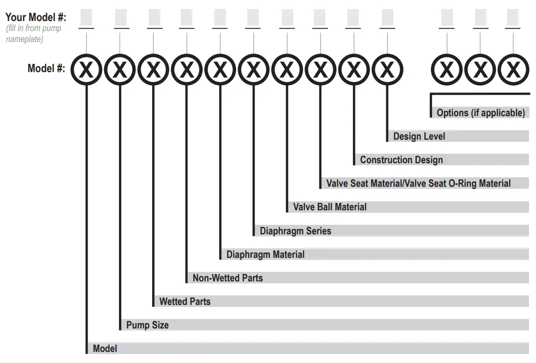
| Model E Elima-MaticPump Size 5 1/2″ | Wetted Parts An Aluminum S Stainless SteelH Alloy C Non-Wetted Parts An Aluminum P Polypropylene | Diaphragm Material / Series 1R Neoprene Rugged 2R Nitrile Rugged 3R (FKM) Fluorocarbon Rugged 4R EPDM Rugged 5T PTFE Tef-Matic (2 pieces) 6X Santoprene (XL) Thermo-Matic 7X Hytrel Thermo-Matic | Valve Ball Material Valve 1 Neoprene 2 Nitrile 3 (FKM) Fluorocarbon 4 EPDM 5 PTFE 6 Santoprene XL 7 Hytrel Stainless Steel Y FDA Santoprene | Seat/Valve Seat O-Ring Material 5 PTFE Construction Design 9 Bolted Design Level A C |
Materials
| Material Profile: | Operating Temperatures: | |
| Max. | Min. | |
| Conductive Acetal: Tough, impact resistant, ductile. Good abrasion resistance and low friction surface. Generally inert, with good chemical resistance except for strong acids and oxidizing agents. | 190°F 88°C | -20°F -29°C |
| EPDM: Shows very good water and chemical resistance. Has poor resistance to oils and solvents, but is fair in ketones and alcohols. | 280°F 138°C | -40°F -40°C |
| FKM: (Fluorocarbon) Shows good resistance to a wide range of oils and solvents; especially all aliphatic, aromatic, and halogenated hydrocarbons, acids, animal and vegetable oils. Hot water or hot aqueous solutions (over 70°F) will attack FKM. | 350°F 177°C | -40°F -40°C |
| Hytrel®: Good on acids, bases, amines and glycols at room temperatures only. | 220°F 104°C | 220°F 104°C |
| Neoprene: All purpose. Resistance to vegetable oils. Generally not affected by moderate chemicals, fats, greases and many oils and solvents. Generally attacked by strong oxidizing acids, ketones, esters and nitro hydrocarbons, and chlorinated aromatic hydrocarbons. | 200°F 93°C | -10°F -23°C |
| Nitrile: General purpose, oil-resistant. Shows good solvent, oil, water, and hydraulic fluid resistance. Should not be used with highly polar solvents like acetone and MEK, ozone, chlorinated hydrocarbons and nitro hydrocarbons. | 190°F 88°C | -10°F -23°C |
| Nylon: 6/6 High strength and toughness over a wide temperature range. Moderate to good resistance to fuels, oils, and chemicals. | 180°F 82°C | 32°F 0°C |
| Polypropylene: A thermoplastic polymer. Moderate tensile and flex strength. Resists strong acids and alkali. Attacked by chlorine, fuming nitric acid, and other strong oxidizing agents. | 180°F 82°C | 32°F 0°C |
| PVDF: (Polyvinylidene Fluoride) A durable fluoroplastic with excellent chemical resistance. Excellent for UV applications. High tensile strength and impact resistance. | 250°F 121°C | 0°F -18°C |
| Santoprene®: Injection molded thermoplastic elastomer with no fabric layer. Long mechanical flex life. Excellent abrasion resistance. | 275°F 135°C | -40°F -40°C |
| UHMW PE: A thermoplastic that is highly resistant to a broad range of chemicals. Exhibits outstanding abrasion and impact resistance, along with environmental stress-cracking resistance. | -40°F -40°C | -35°F -37°C |
| Urethane: Shows good resistance to abrasives. Has poor resistance to most solvents and oils. | 150°F 66°C | 32°F 0°C |
| Virgin PTFE: (PFA/TFE) Chemically inert, virtually impervious. Very few chemicals are known to chemically react with PTFE; molten alkali metals, turbulent liquid or gaseous fluorine, and a few fluoro-chemicals such as chlorine trifluoride or oxygen difluoride which readily liberate free fluorine at elevated temperatures. | 220°F 104°C | -35°F -37°C |
Maximum and Minimum Temperatures are the limits for which these materials can be operated. Temperatures coupled with pressure affect the longevity of diaphragm pump components. Maximum life should not be expected at the extreme limits of the temperature ranges.
Metals:
Alloy C: Equal to ASTM494 CW-12M-1 specification for nickel and nickel alloy. Stainless Steel: Equal to or exceeding ASTM specification A743 CF-8M for corrosion-resistant iron chromium, iron chromium-nickel, and nickel-based alloy castings for general applications. Commonly referred to as 316 Stainless Steel in the pump industry.
Performance
E7 3/4″ Bolted Metal Rubber and TPE Fitted
Flow Rate
Adjustable to ……….0-12 gpm (45.4 lpm)
Port Size
Suction ……………………3/4″ NPT
Discharge ………………….3/4″ NPT
Air Inlet ……………………3/8″ NPT
Air Exhaust ………………..3/8″ NPT
Suction Lift
Dry ……………………. 13′ (3.9 m)
Wet……………………. 22′ (6.7 m)
Max Solid Size (Diameter)
…………………….1/16″ (1.6 mm)
Max Noise Level ……………84 dB(A)
Shipping Weights
Aluminum ………………11 lbs (3.9 kg)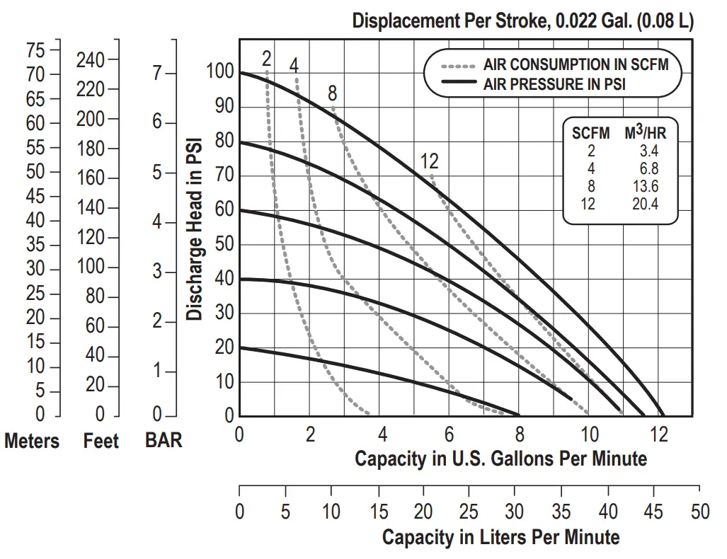
NOTE: Performance based on the following: PTFE fitted pump, flooded suction, water at ambient conditions. The use of other materials and varying hydraulic conditions may result in deviations in excess of 5%.
E7 3/4″ Bolted Metal
PTFE Fitted
Flow Rate
Adjustable to ……….0-11 gpm (41.6 lpm)
Port Size
Suction ……………………3/4″ NPT
Discharge ………………….3/4″ NPT
Air Inlet ……………………3/8″ NPT
Air Exhaust ………………..3/8″ NPT
Suction Lift
Dry ……………………. 12′ (3.6 m)
Wet……………………. 22′ (6.7 m)
Max Solid Size (Diameter)
…………………….1/16″ (1.6 mm)
Max Noise Level ……………87 dB(A)
Shipping Weights
Aluminum ………………11 lbs (3.9 kg)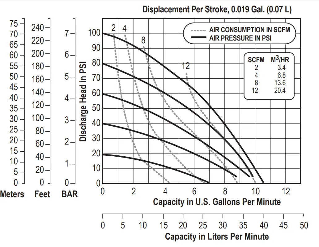
NOTE: Performance based on the following: PTFE fitted pump, flooded suction, water at ambient conditions. The use of other materials and varying hydraulic conditions may result in deviations in excess of 5%.
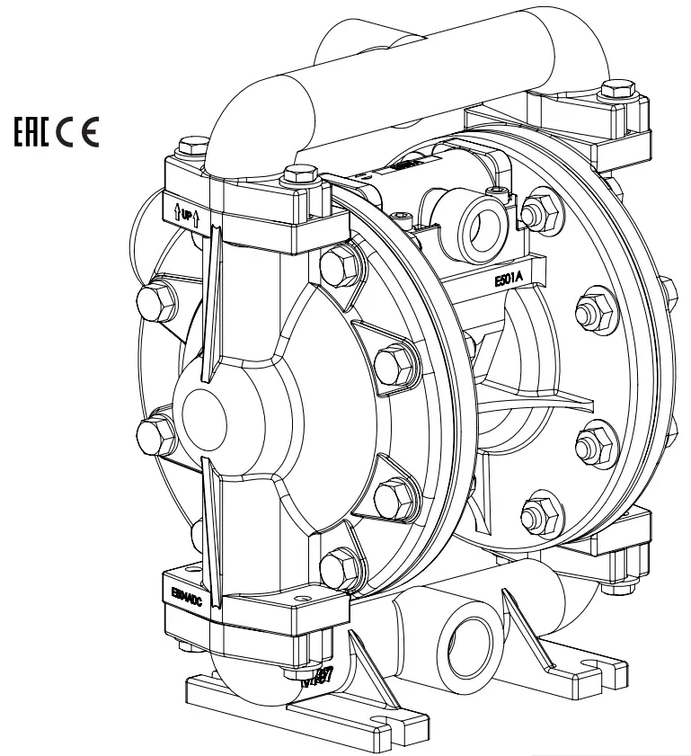
Dimensional Drawings
E7 Bolted Metal
Dimensions in inches (mm dimensions in brackets).
The dimensions on this drawing are for reference only. A certified drawing can be requested if physical dimensions are needed.
Principle of Pump Operation
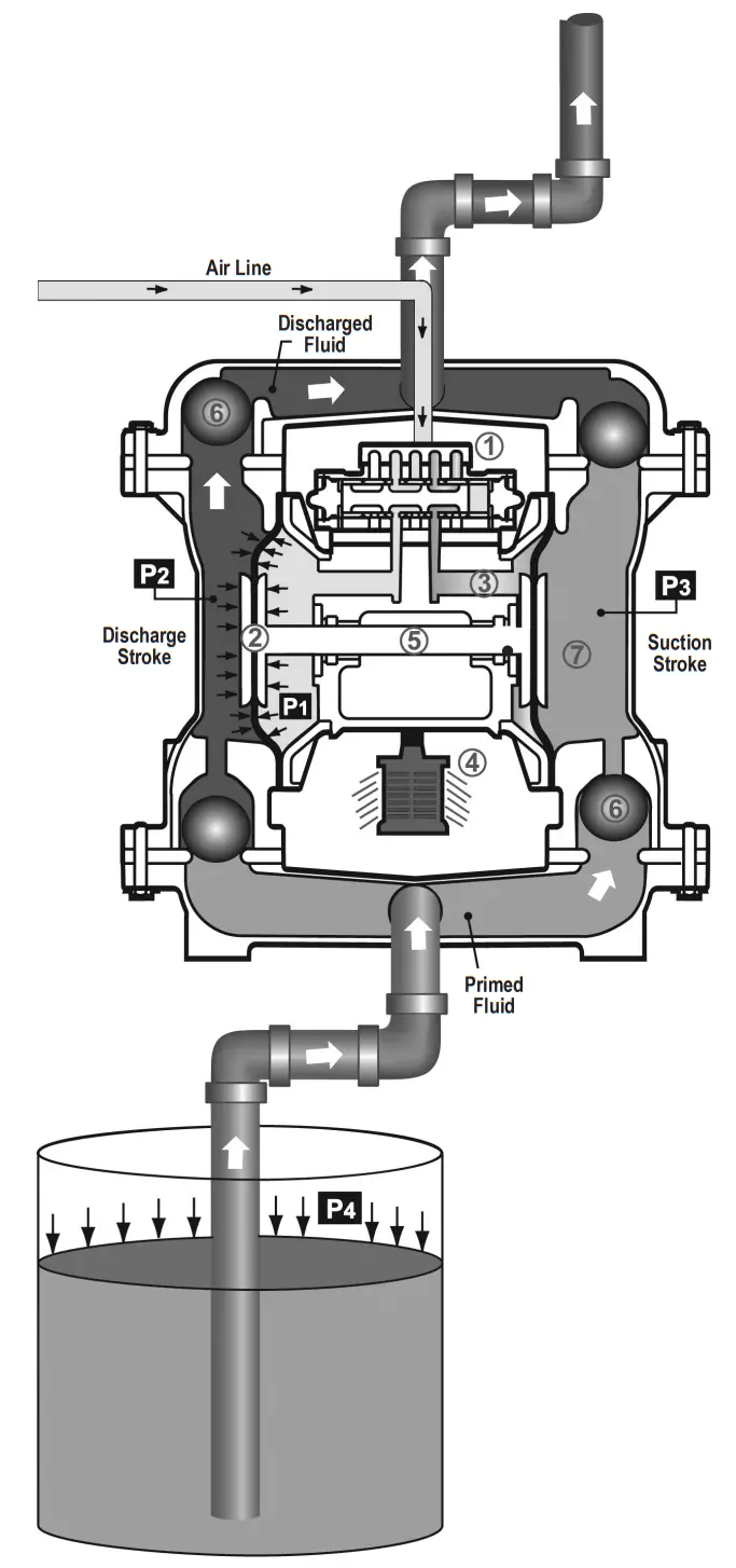
Air-Operated Double Diaphragm (AODD) pumps are powered by compressed air or nitrogen.
The main directional (air) control valve ① distributes compressed air to an air chamber, exerting uniform pressure over the inner surface of the diaphragm ②. At the same time,
the exhausting air ③ from behind the opposite diaphragm is directed through the air valve assembly(s) to an exhaust port ④.
As inner chamber pressure (P1) exceeds liquid chamber pressure (P2), the rod ⑤ connected diaphragms shift together creating discharge on one side and suction on the
opposite side. The discharged and primed liquid’s directions are controlled by the check valves (ball or flap)⑥ orientation.
The pump primes as a result of the suction stroke. The suction stroke lowers the chamber pressure (P3) increasing the chamber volume. This results in a pressure differential
necessary for atmospheric pressure (P4) to push the fluid through the suction piping and across the suction side check valve and into the outer fluid chamber ⑦.
Suction (side) stroking also initiates the reciprocating (shifting, stroking or cycling) action of the pump. The suction diaphragm’s movement is mechanically pulled through its
stroke. The diaphragm’s inner plate makes contact with an actuator plunger aligned to shift the pilot signaling valve. Once actuated, the pilot valve sends a pressure signal to the
opposite end of the main directional air valve, redirecting the compressed air to the opposite inner chamber.
SUBMERGED ILLUSTRATION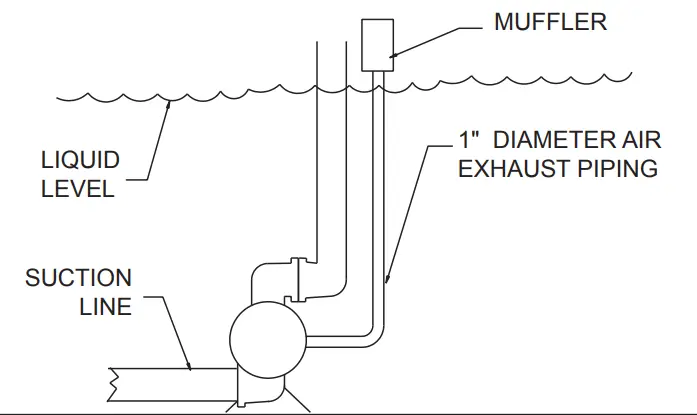
The pump can be submerged if the pump materials of construction are compatible with the liquid being pumped. The air exhaust must be piped above the liquid level. When the pumped product source is at a higher level than the pump (flooded suction condition), pipe the exhaust higher than the product source to prevent siphoning spills.
Recommended Installation Guide
Available Accessories:
- Surge Suppressor
- Filter/Regulator
- Air Dryer
- Lubricator
Note: Surge Suppressor and Piping, including air line, must be supported after the flexible connections.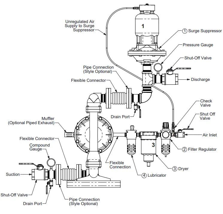
![]() CAUTION
CAUTION
The air exhaust should be piped to an area for safe disposition of the product being pumped, in the event of a diaphragm failure.
Installation And Start-Up
Locate the pump as close to the product being pumped as possible. Keep the suction line length and number of fittings to a minimum. Do not reduce the suction line diameter.
Air Supply
Connect the pump air inlet to an air supply with sufficient capacity and pressure to achieve desired performance. A pressure regulating valve should be installed to ensure air supply pressure does not exceed recommended limits.
Air Valve Lubrication
The air distribution system is designed to operate WITHOUT lubrication. This is the standard mode of operation. If lubrication is desired, install an air line lubricator set to deliver one drop of SAE 10 non-detergent oil for every 20 SCFM (9.4 liters/sec.) of air the pump consumes. Consult the Performance Curve to determine air consumption.
Air Line Moisture
Water in the compressed air supply may cause icing or freezing of the exhaust air, causing the pump to cycle erratically or stop operating. Water in the air supply can be reduced by using a point-of-use air dryer.
Air Inlet And Priming
To start the pump, slightly open the air shut-off valve. After the pump primes, the air valve can be opened to increase airflow as desired. If opening the valve increases the cycling rate, but does not increase the rate of flow, cavitation has occurred. The valve should be closed slightly to obtain the most efficient airflow to pump flow ratio.
Troubleshooting Guide
Symptom: | Potential Cause(s): | Recommendation(s): |
| Pump Cycles Once | Deadhead (system pressure meets or exceeds air supply pressure). | Increase the inlet air pressure to the pump. The pump is designed for a 1:1 pressure ratio at zero flow. (Does not apply to high pressure 2:1 units). |
| Air valve or intermediate gaskets installed incorrectly. | Install gaskets with holes properly aligned. | |
| Bent or missing actuator plunger. | Remove the pilot valve and inspect the actuator plungers. | |
| Pump Will Not Operate / Cycle | The pump is over-lubricated. | Set lubricator on lowest possible setting or remove. Units are designed for lube-free operation. |
| Lack of air (line size, PSI, CFM). | Check the airline size and length, and compressor capacity (HP vs. cfm required). | |
| Check the air distribution system. | Disassemble and inspect the main air distribution valve, pilot valve, and pilot valve actuators. | |
| The discharge line is blocked or clogged manifolds. | Check for inadvertently closed discharge line valves. Clean discharge manifolds/piping. | |
| Deadhead (system pressure meets or exceeds air supply pressure). | Increase the inlet air pressure to the pump. The pump is designed for 1:1 pressure ratio at zero flow. (Does not apply to high pressure 2:1 units). | |
| Blocked air exhaust muffler. | Remove the muffler screen, clean or de-ice, and re-install. | |
| Pumped fluid in air exhaust muffler. | Disassemble pump chambers. Inspect for diaphragm rupture or loose diaphragm plate assembly. | |
| The pump chamber is blocked. | Disassemble and inspect wetted chambers. Remove or flush any obstructions. | |
| Pump Cycles and Will Not Prime or No Flow | Cavitation on the suction side. | Check suction condition (move pump closer to product). |
| Check valve obstructed. Valve ball(s) not seating properly or sticking. | Disassemble the wet end of the pump and manually dislodge the obstruction in the check valve pocket. Clean out around valve ball cage and valve seat area. Replace valve ball or valve seat if damaged. Use heavier valve ball material. | |
| Valve ball(s) missing (pushed into chamber or manifold). | Worn valve ball or valve seat. Worn fingers in valve ball cage (replace part). Check Chemical Resistance Guide for compatibility. | |
| Valve ball(s)/seat(s) damaged or attacked by product. | Check Chemical Resistance Guide for compatibility. | |
| Check valve and/or seat is worn or need adjusting. | Inspect and check valves and seats for wear and proper setting. Replace if necessary. | |
| The suction line is blocked. | Remove or flush obstruction. Check and clear all suction screens or strainers. | |
| Excessive suction lift. | For lifts exceeding 20’ of liquid, filling the chambers with liquid will prime the pump in most cases. | |
| Suction side air leakage or air in product. | Visually inspect all suction-side gaskets and pipe connections. | |
| Pumped fluid in air exhaust muffler. | Disassemble pump chambers. Inspect for diaphragm rupture or loose diaphragm plate assembly. | |
| Pump Cycles Running Sluggish/Stalling, Flow Unsatisfactory | Over lubrication. | Set lubricator on lowest possible setting or remove. Units are designed for lube-free operation. |
| Icing. | Remove the muffler screen, de-ice, and re-install. Install a point-of-use air drier. | |
| Clogged manifolds. | Clean manifolds to allow proper airflow | |
| Deadhead (system pressure meets or exceeds air supply pressure). | Increase the inlet air pressure to the pump. The pump is designed for a 1:1 pressure ratio at zero flow. (Does not apply to high pressure 2:1 units). | |
| Cavitation on the suction side. | Check suction (move pump closer to product). | |
| Lack of air (line size, PSI, CFM). | Check the airline size, length, and compressor capacity. | |
| Excessive suction lift. | For lifts exceeding 20’ of liquid, filling the chambers with liquid will prime the pump in most cases. | |
| Air supply pressure or volume exceeds system HD. | Decrease inlet air (press. and vol.) to the pump. The pump is cavitating the fluid by fast cycling. | |
| Undersized suction line. | Meet or exceed pump connections. | |
| Restrictive or undersized airline. | Install a larger airline and connection. | |
| Suction side air leakage or air in product. | Visually inspect all suction-side gaskets and pipe connections. | |
| The suction line is blocked. | Remove or flush obstruction. Check and clear all suction screens or strainers. | |
| Pumped fluid in air exhaust muffler. | Disassemble pump chambers. Inspect for diaphragm rupture or loose diaphragm plate assembly. | |
| Check valve obstructed. | Disassemble the wet end of the pump and manually dislodge the obstruction in the check valve pocket. | |
| Check valve and/or seat is worn or need adjusting. | Inspect and check valves and seats for wear and proper setting. Replace if necessary. | |
| Entrained air or vapor lock in the chamber(s). | Purge chambers through tapped chamber vent plugs. Purging the chambers of air can be dangerous. | |
| Product Leaking Through Exhaust | Diaphragm failure or diaphragm plates loss. | Replace diaphragms, check for damage and ensure diaphragm plates are tight. |
| The diaphragm stretched around the center hole or bolt holes. | Check for excessive inlet pressure or air pressure. Consult Chemical Resistance Chart for compatibility with products, cleaners, temperature limitations, and lubrication. | |
| Premature Diaphragm Failure | Cavitation. | Enlarge pipe diameter on the suction side of the pump. |
| Excessive flooded suction pressure. | Move the pump closer to the product. Raise pump/place pump on top of the tank to reduce inlet pressure. Install Back pressure device (Tech bulletin 41r). Add accumulation tank or pulsation dampener. | |
| Misapplication (chemical/physical incompatibility). | Consult Chemical Resistance Chart for compatibility with products, cleaners, temperature limitations and lubrication. | |
| Incorrect diaphragm plates or plates on backward installed incorrectly or worn. | Check Operating Manual to check for correct parts and installation. Ensure outer plates have not been worn to a sharp edge. | |
| Unbalanced Cycling | Excessive suction lift. | For lifts exceeding 20’ of liquid, filling the chambers with liquid will prime the pump in most cases. |
| Undersized suction line. | Meet or exceed pump connections. | |
| Pumped fluid in air exhaust muffler. | Disassemble pump chambers. Inspect for diaphragm rupture or loose diaphragm plate assembly. | |
| Suction side air leakage or air in product. | Visually inspect all suction-side gaskets and pipe connections. | |
| Check valve obstructed. | Disassemble the wet end of the pump and manually dislodge the obstruction in the check valve pocket. | |
| Check valve and/or seat is worn or need adjusting. | Inspect and check valves and seats for wear and proper setting. Replace if necessary. | |
| Entrained air or vapor lock in the chamber(s). | Purge chambers through tapped chamber vent plugs. | |
Composite Repair Parts Drawing
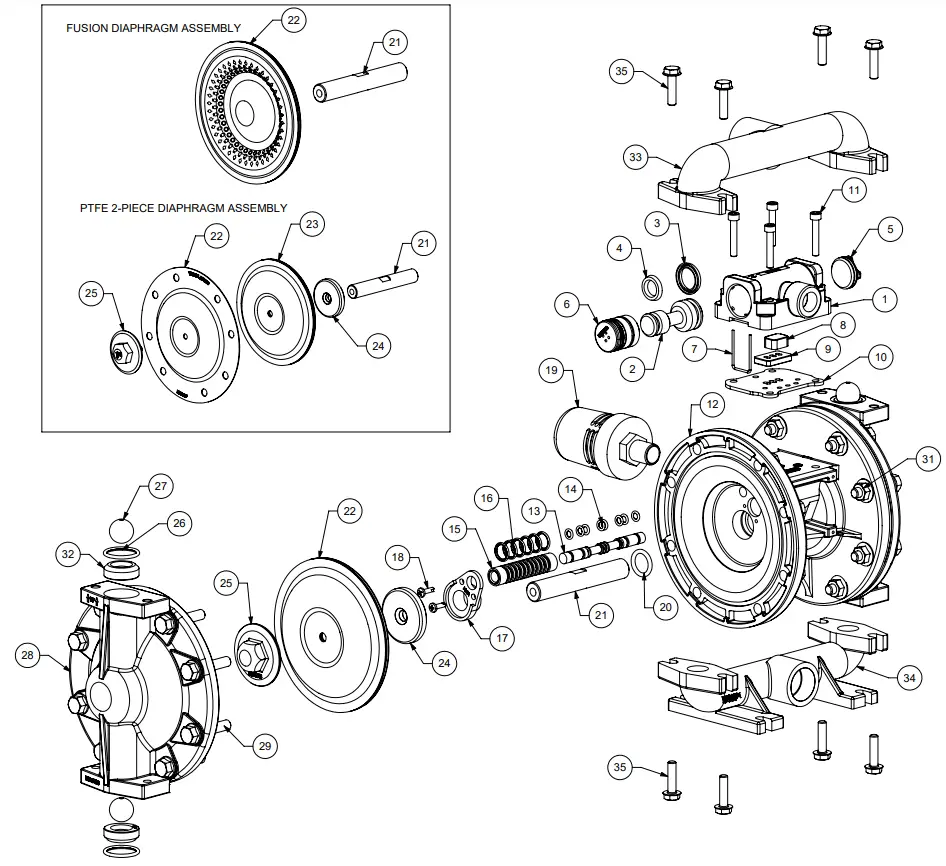
Composite Repair Parts List
Air Valve Assembly
| Item # | Qty. | Description | Part Number |
| Air Side Repair Kit (Includes Items 3.4,6, 8-10,13-17,20) | 476.V007.000 | ||
| – | 1 | Valve Body (includes items 1-11) | 031.V004.552 |
| 1 | 1 | Valve Body | E500A |
| 2 | 1 | Valve Spool Assembly (Includes items 38A) | E500BUB ASY |
| 3 | 1 | Large Valve Spool U-Cup | P98-104A |
| 4 | 1 | Small Valve Spool U-Cup | P98-104AUB |
| 5 | 1 | End Cap Assembly (Includes 0-Ring) | E500D |
| 6 | 1 | Reducing End Cap Assembly (Includes 560.0580.360 0-rings) | E500DUB ASY |
| 7 | 2 | Staple | E500F |
| 8 | 1 | CT Air Diverter | 10-075 |
| 9 | 1 | Air Diverter Plate | E500H |
| 10 | 1 | Air Valve Gasket | 360.V003.360 |
| 11 | 4 | Valve Mounting Screws | S1004 |
Center Section Assembly
| Item # | Qty. | Description | Pad Number | |
| Polypropylene | Aluminum | |||
| 12 | 1 | Center Section | E501A | E501A-SC |
| Pilot Repair Kit (Includes Items 13-17) | 476.V006.000 | |||
| 13 | 1 | Pilot Spool ASY (Includes Item #14) | 775.V003.000 | |
| 14 | 8 | Pilot Spool 0-Rings | 560.023.358 | |
| 15 | 1 | Pilot Valve Sleeve ASY (Includes Item #16) | 755.V003.000 | |
| 16 | 6 | Pilot Valve Sleeve 0-Rings | 560.033.358 | |
| 17 | 2 | Shaft/Pilot Retainer | 670.V001.554 | |
| 18 | 4 | Retainer Screw | E501C | |
| 19 | 1 | Muffler | 530.024.000 | |
Diaphragm Assembly / Elastomers
| Item # | Qty. | Description | Pad Number | ||||
| TPE/RUBBER | PTFE 2-iece | I PTFE Fusion | |||||
| 20 | 2 | Main Shaft 0-Ring | E502B | ||||
| 21 | 1 | Main Shaft | E502A | ||||
| 22 | 2 | Diaphragm | “E505xx (See Below Material Chart)” | E505TF | E505F | ||
| 23 | 2 | Back-Up Diaphragm | N/A | E505N | N/A | ||
| 24 | 2 | Inner Diaphragm Plate | V199C | N/A | |||
| 25 | 2 | Outer Diaphragm Plate | SV199B | N/A | |||
| 26 | 4 | Valve Seat 0-Ring | “V110xx (See Below Material Chart)” | V110HT | |||
| 27 | 4 | Valve Ball | “V111xx (See Below Material Chart)” | V111SS, V111TF | |||
Wet End Assembly
| Item # | Qty. | Description | Pad Number |
| Aluminum | |||
| 28 | 2 | Water Chamber | E504A |
| 29 | 16 | Water Chamber Bolt | 171.064.115 |
| 31 | 16 | Water Chamber Nut | SV185B |
| 32 | 4 | Valve Seat | V110A |
| 33 | 1 | Discharge Manifold | V196A |
| 34 | 1 | Suction Manifold | V197A |
| 35 | 8 | Manifold Bolts | 171.065.115 |
Elastomer Material Specifications
| Material | Diaphragm P/N | Valve Ball P/N | 0-Ring P/N |
| Neoprene | E505N | N/A | N/A |
| Buna Nitrile | E505BN | V111BN | V110BN |
| Viton | E505VT | V111 VT | V110VT |
| Model | E505ND | N/A | V110ND |
| Santoprene | E505XL | V111TPEXL | V110XL |
| Stainless Steel | N/A | V111SS | N/A |
Material Codes – The Last 3 Digits of Part Number
| 000…..Assembly, sub-assembly; and some purchased items 010…..Cast Iron 015…..Ductile Iron 020…..Ferritic Malleable Iron 080…..Carbon Steel, AISI B-1112 110 …..Alloy Type 316 Stainless Steel 111 …..Alloy Type 316 Stainless Steel (Electro Polished) 112 …..Alloy C 113 …..Alloy Type 316 Stainless Steel (Hand Polished) 114 …..303 Stainless Steel 115 …..302/304 Stainless Steel 117 …..440-C Stainless Steel (Martensitic) 120…..416 Stainless Steel (Wrought Martensitic) 148…..Hardcoat Anodized Aluminum 150…..6061-T6 Aluminum 152…..2024-T4 Aluminum (2023-T351) 155…..356-T6 Aluminum 156…..356-T6 Aluminum 157…..Die Cast Aluminum Alloy #380 158…..Aluminum Alloy SR-319 162…..Brass, Yellow, Screw Machine Stock 165…..Cast Bronze, 85-5-5-5 166…..Bronze, SAE 660 170…..Bronze, Bearing Type, Oil Impregnated 180…..Copper Alloy 305…..Carbon Steel, Black Epoxy Coated 306…..Carbon Steel, Black PTFE Coated 307…..Aluminum, Black Epoxy Coated 308…..Stainless Steel, Black PTFE Coated 309…..Aluminum, Black PTFE Coated 313…..Aluminum, White Epoxy Coated 330…..Zinc Plated Steel 332…..Aluminum, Electroless Nickel Plated 333…..Carbon Steel, Electroless Nickel Plated 335…..Galvanized Steel 337…..Silver Plated Steel 351…..Food Grade Santoprene® 353…..Geolast; Color: Black 354…..Injection Molded #203-40 Santoprene® Duro 40D +/-5; Color: RED 356…..Hytrel® 357…..Injection Molded Polyurethane 358…..Urethane Rubber (Some Applications) (Compression Mold) 359…..Urethane Rubber 360…..Nitrile Rubber Color coded: RED 363…..FKM (Fluorocarbon) Color-coded: YELLOW | 364…..EPDM Rubber Color-coded: BLUE 365…..Neoprene Rubber Color-coded: GREEN 366…..Food Grade Nitrile 368…..Food Grade EPDM 371…..Philthane (Tuftane) 374…..Carboxylated Nitrile 375…..Fluorinated Nitrile 378…..High-Density Polypropylene 379…..Conductive Nitrile 408…..Cork and Neoprene 425…..Compressed Fibre 426…..Blue Gard 440…..Vegetable Fibre 500…..Delrin®500 502…..Conductive Acetal, ESD-800 503…..Conductive Acetal, Glass-Filled 506…..Delrin®150 520…..Injection Molded PVDF Natural color 540…..Nylon 542…..Nylon 544…..Nylon Injection Molded 550…..Polyethylene 551…..Glass Filled Polypropylene 552…..Unfilled Polypropylene 555…..Polyvinyl Chloride 556…..Black Vinyl 558…..Conductive HDPE 570…..Rulon II® 580…..Ryton® 600…..PTFE (virgin material) Tetrafluorocarbon (TFE) 603…..Blue Gylon® 604…..PTFE 606…..PTFE 607…..Evelyn 608…..Conductive PTFE 610…..PTFE Encapsulated Silicon 611 …..PTFE Encapsulated FKM 632…..Neoprene/Hytrel® 633…..FKM/PTFE 634…..EPDM/PTFE 635…..Neoprene/PTFE 637…..PTFE, FKM/PTFE 638…..PTFE, Hytrel®/PTFE 639…..Nitrile/TFE 643…..Santoprene®/EPDM 644…..Santoprene®/PTFE 656 …..Santoprene® Diaphragm and Check Balls/EPDM Seats 661…..EPDM/Santoprene® 666…..FDA Nitrile Diaphragm, PTFE Overlay, Balls, and Seals 668…..PTFE, FDA Santoprene®/PTFE |
- Delrin and Hytrel are registered tradenames of E.I. DuPont.
- Nylatron is a registered tradename of Polymer Corp.
- Nylon is a registered tradename of Garlock, Inc.
- Santoprene is a registered tradename of Exxon Mobil Corp.
- Rulon II is a registered tradename of Dixion Industries Corp.
- Ryton is a registered tradename of Phillips Chemical Co.
- Valox is a registered tradename of General Electric Co.
RECYCLING
Warren Rupp, the manufacturer of Versamatic, is an ISO14001 registered company and is committed to minimizing the impact our products have on the environment. Many components of Versamatic® AODD pumps are made of recyclable materials. We encourage pump users to recycle worn-out parts and pumps whenever possible after any hazardous pumped fluids are thoroughly flushed. Pump users that recycle will gain the satisfaction to know that their discarded part(s) or pump will not end up in a landfill. The recyclability of Versamatic products is a vital part of Warren Rupp’s commitment to environmental stewardship.
5 – YEAR Limited Product Warranty
Quality System ISO9001 Certified • Environmental Management Systems ISO14001 Certified
Versamatic warrants to the original end-use purchaser that no product sold by Versamatic that bears a Versamatic brand shall fail under normal use and service due to a defect in material or workmanship within five years from the date of shipment from Versamatic’s factory.
The use of non-OEM replacement parts will void (or negate) agency certifications, including CE, ATEX, CSA, 3A and EC1935 compliance (Food Contact Materials). Warren Rupp, Inc. cannot ensure nor warrant non-OEM parts to meet the stringent requirements of the certifying agencies.
~ See complete warranty at http://vm.salesmrc.com/pdfs/VM_Product_Warranty.pdf
DECLARATION OF CONFORMITY
MANUFACTURED BY:
| FABRIQUE PAR: FABRICADA POR: HERGESTELLT VON: FABBRICATO DA: VERVAARDIGD DOOR: TILLVERKAD AV: FABRIKANT: VALMISTAJA: PRODUSENT: FABRICANTE: | VERSAMATIC® Warren Rupp, Inc. A Unit of IDEX Corporation 800 North Main Street P.O. Box 1568 Mansfield, OH 44901-1568 the USA Tel: 419-526-7296 Fax: 419-526-7289 |
PUMP MODEL SERIES: E SERIES, V SERIES, VT SERIES, VSMA3, SPA15, RE SERIES, AND U2 SERIES
This product complies with the following European Community Directives:
2006/42/EC on Machinery, according to Annex VIII
This product has used the following harmonized standards to verify conformance:
EN809:2012
![]() APPROVED BY
APPROVED BY
Dave Roseberry![]()
Director of Engineering DATE: February 27, 2017


