ABH MANUFACTURING INC A240HD Aluminum Geared Hinge
INSTALLATION INSTRUCTIONS FOR FULL CONCEALED HINGES
A110HD/LL, A111HD/LL, A130HD, A135HD, A140HD/LL, A150HD/LL, A160HD/LL
A240HD/LL, A260HD/LL, A270HD/LL, A280HD/LL & A410HD/LL
- All uncut standard length hinges are non-handed and can be used for right or left hand doors.
- Standard length hinges are supplied slightly shorter than nominal door height to accommodate threshold and carpeting clearances.
CUTTING THE HINGE TO FIT
- Keep hinge in the closed position
- Determine HANDING if required. Not all hinges will become handed after cutting.
- Cut one end of the hinge only. Cut end will be installed at the bottom (Six-hole pattern remains at the top)
- Use a Metal Cutting Saw cut through the gear cap first.
Note: If cut length interferes with a set screw bearing remove it and switch it with a plain bearing above the cut location.
FRAME PREP
With the hinge in the open position
- Locate the top of the hinge 1/8″ below the header With the frame leaf flange tight against the frame
- Mark or Center Punch hole locations
Note: If using wood screws drill a 5/32″ pilot hole DO NOT ATTACH HINGE TO FRAME AT THIS TIME
ATTACH THE HINGE TO THE DOOR - Position Door Leaf on door. Door leaf alignment flange or door leaf lip must be seated against door edge.
- Align the top end of the hinge to be absolutely flush with the top of the door.
- Mark or Center Punch hole locations
- Using the provided Self Drilling/Thread Forming Screws and the proper drive bit please proceed to attach the hinge to the door Note: If using wood screws drill a 5/32″ pilot hole.
ATTACHING DOOR TO FRAME - Position door 90 degrees to frame
- Shim door to the proper height to line up the screw holes in hinge frame leaf with the marks at the top of the frame.
- Install two screws at the top of the hinge to hold in place
- Remove shim and align the remaining holes. Install two additional screws in the middle and at the bottom.
- Check door for proper swing and clearance before installing remaining screws, making necessary adjustments.
- Install the remaining fasteners after any adjustments are made.
REINFORCING AND RIVNUTS
- No reinforcing is necessary except on extremely high-frequency, extremely heavy or extra-wide doors.
- Rivne’s are recommended for use in the frame when the door exceeds 450lbs.
Note: RIVNUTS are not to be used with Fire Rated Hinges
PAIRS OF DOORS WITH MULLIONS
- If the mullion is between the doors, install as single doors.
- If the mullion is behind the doors, install as a double doors.
GROUT/SLUSHED-IN FRAMES
It is recommended that a mudguard be installed behind the frame for ease of installation. Do not use self-drill screws with grouted steel frames without a mudguard. If no mudguard has been used, drill holes through frame and remove grout for screw clearances. Do not oversize hole.
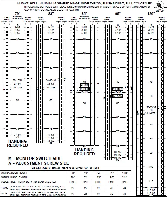
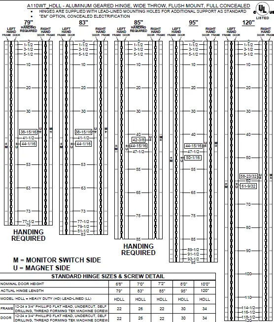
| SCREW DETAIL | |
| FRAME | 12-24 x 3/4″ PHILLIPS FLAT HEAD, UNDERCUT, SELF DRILLING, THREAD FORMING TEK MACHINE SCREW |
| DOOR | 12-24 x 3/4″ PHILLIPS FLAT HEAD, UNDERCUT, SELF DRILLING, THREAD FORMING TEK MACHINE SCREW |
Note: #12 x 1-1/2″ FLAT HEAD UNDERCUT WOOD SCREWS AVAILABLE UPON REQUEST
The following actions will void any warranty, expressed or implied.
- Failure to Install the hinge according to ABH’s specifications and requirements
- Use of Fasteners other than those supplied with the hinge.
- Unauthorized field modifications including removing any of the bearings, altering the original finish or painting the hinge.
NOTES:
- HINGES CUT TO CUSTOM LENGTH ARE CUT FROM THE BOTTOM.
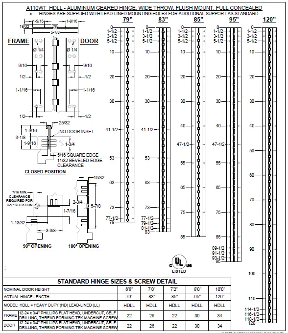
- ALL DIMENSIONS ARE IN INCHES.
- ALL DIMENSIONS ARE TO CENTERLINE OF HOLES.
NOTES:
- HINGES CUT TO CUSTOM LENGTH ARE CUT FROM BOTTOM OF HINGE.
- SPECIFY HANDING WHEN ORDERING.
- IF “M” OPTION (MOVEABLE PANEL) OR “R” OPTION (REMOVABLE PANEL) IS CHOSEN, TEMPLATE REMAINS THE SAME.
NOTES:
- HINGES CUT TO CUSTOM LENGTH ARE CUT FROM BOTTOM OF HINGE.
- SPECIFY HANDING WHEN ORDERING.
- IF “M” OPTION (MOVEABLE PANEL) OR “R” OPTION (REMOVABLE PANEL) IS CHOSEN, TEMPLATE REMAINS THE SAME.

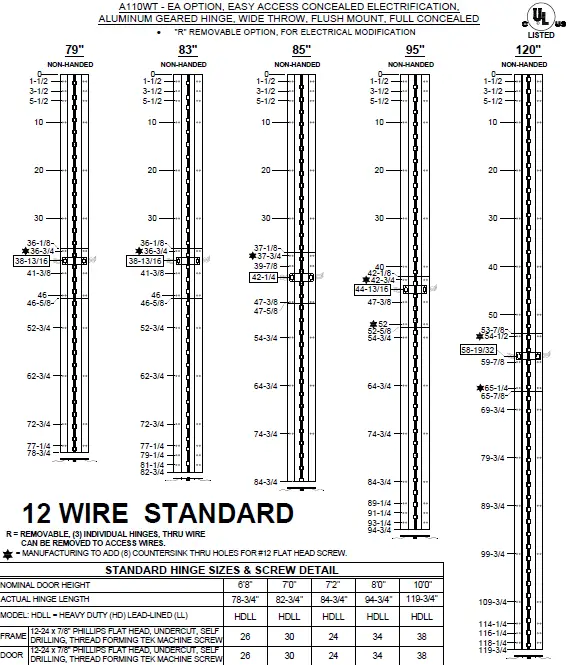
NOTES:
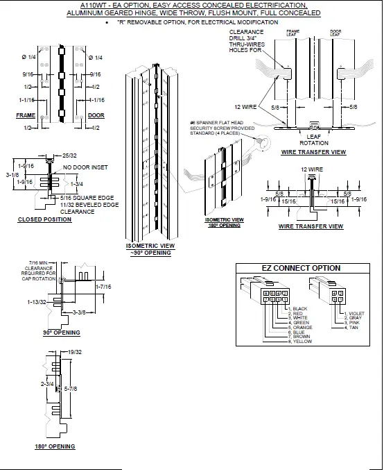
- MOLEX CONNECTOR OPTION AVAILABLE – SUFFIX “EZ”.
* SPECIFY ELECTRIFIED HARDWARE MANUFACTURER FOR CONNECTOR COMPABILITY
SPECIFICATION:
- DESCRIPTION: SINGLE CONDUCTOR #22 AWG MINIATURE HOOK-UP WIRE FOR APPLICATIONS REQUIRING EXTREME FLEXIBILITY.
- CONDUCTOR: #22 AWG 168/44 (0.002″) SOFT BARE COPPER LHL.
- INSULATION: PROPRIETARY FORMULATION PVC 0.010″ NOM. WALL MEETS VW-1 FLAME REQUIREMENT.
- DIAMETER: 0.053″ ± 0.003″.
- RESISTANCE: 16.7 OHMS MAX. @ 20°C, PER 1000 FT.
- VOLTAGE RATING: 600 VOLTS RMS, DEPENDING ON SPECIFICATION. AVAILABLE AS RoHS COMPLIANT.
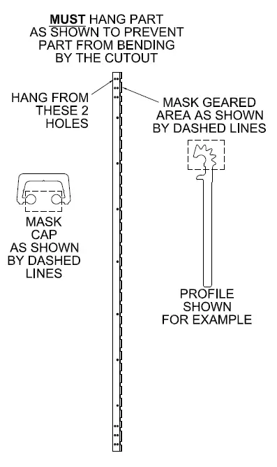
POWDER COAT MASKING