Dettson Atmos Heat Pump 24V Adapter Kit Installation Guide
Safety
Follow all safety information provided in the outdoor unit manual X62434.
![]() Warning
Warning
All electric work must be performed by a licensed technician according to local regulations and the instructions given in this manual. Do not operate with wet hands.
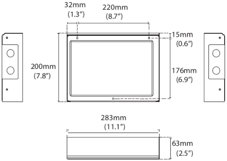
Dimensions
Location
This adapter must be installed indoors, in an area free of drips, moisture and condensation.
Maintain at least 5.9″ (150mm) spacing to walls and ensure it is elevated from areas that can retain water.”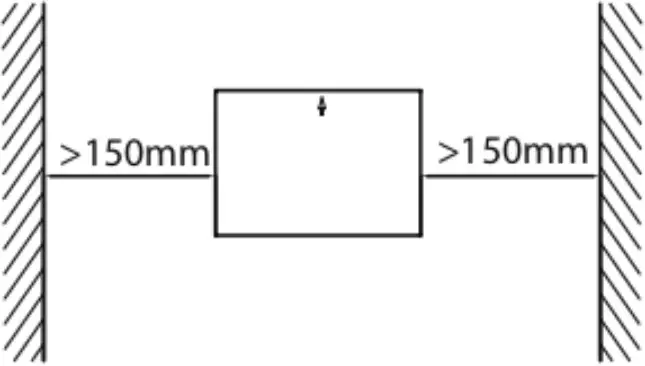
![]() Warning
Warning
Do not install the adapter near flammable liquids or gases.
Installation
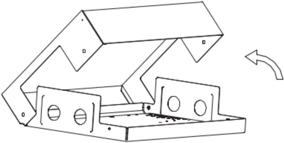
- Remove the cover of the adapter box by removing the 8 exposed screws.

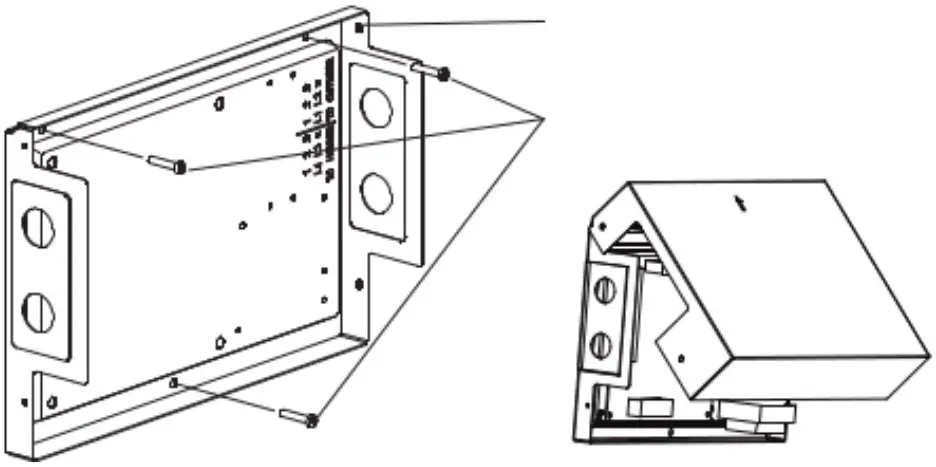
- Mount the back plate of the box vertically on a wall using 3 screws (M4x20) and anchors. The direction of the arrow on the cover must point upwards.

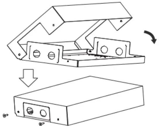
- Wire and configure the control box (see following sections).
- Reattach the cover using the screws.

Important notes:
- TXV or other metering devices must be removed from the indoor coil.
- Both refrigerant lines must be insulated.
- The airflow should be set nearest to 400 CFM/ton.
Wiring
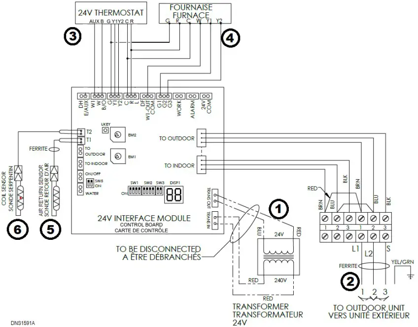
This figure shows the recommended wiring setup for a 3-heat 2-cool heat pump thermostat.
Important notes:
- The power to the indoor and outdoor units must be disconnected before any wiring.
- Make sure that the provided ferrite clamps are installed on the return temperature sensor and the outdoor unit cable.
- The outdoor unit cable is protected by the outdoor unit breaker and must be sized appropriately, according to the nameplate of the outdoor unit.
Wiring steps:
- Disconnect the transformer from the board (TRANS_IN and TRANS_OUT).
- Connect 1, 2 and 3 from the outdoor unit to the control box. Use the ferrite clap.
- Connect the thermostat.
- Connect together R of the thermostat, the furnace and the control board.
- Connect together C of the thermostat, the furnace and the control board.
- Connect together G of the thermostat, the furnace and the control board.
- Connect B of the thermostat to B/O on the control board. Make sure the thermostat is set to output a B signal.
- Connect Y2 and Y1 of the thermostat to the control board.
- Connect AUX (3rd heating stage) of the thermostat to the control board. Connect to W1 to stop the heat pump when auxiliary heat kicks in. Connect to E/AUX to keep the heat pump running with the auxiliary heat.
If using only one cooling stage, ignore the Y2 wire.
If using a conventional thermostat (no B signal), connect W of the thermostat to W on the control board and ignore the B wire.
- Connect the furnace.
- Connect the first fan speed G1 of the control board to Y1 of the furnace.
- If the furnace provides a second cooling speed (Y2), connect the third fan speed G3 of the control board to Y2 of the furnace.
- Connect W1-out of the control board to W of the furnace.
- To turn on the auxiliary heat during the defrost cycle, also connect DF to W of the furnace (see section 8.1).
- Connect the return air sensor to T1 of the control board and install it in the return air duct. The wire length must not exceed 23’ (7m).
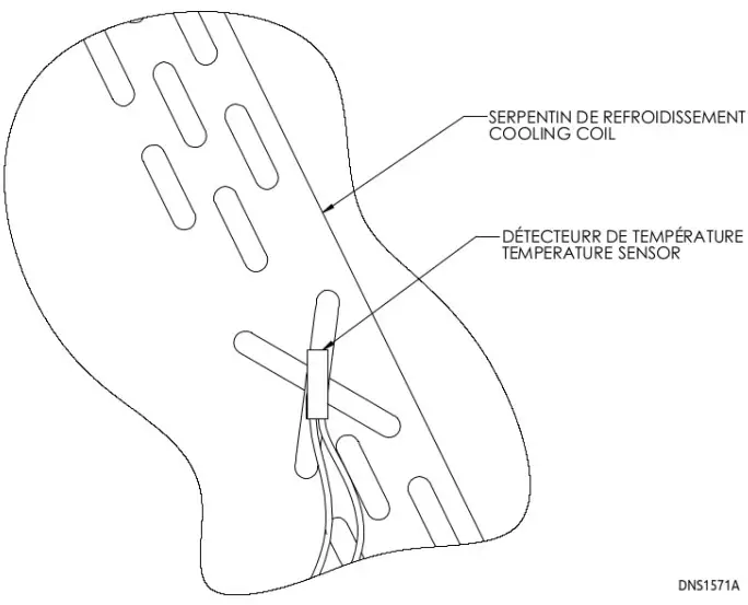
- Attach the coil sensor to the indoor coil as shown: using the provided clip, fix it on the crossover at mid-height of the coil. Run the wire through the refrigerant line opening and connect it to T2 on the control board.

Connection Terminals
| Connection | Direction | Description |
| 24V-COM | Output | 24V output activated when system is running |
| ALARM | Output | Dry contact closed on system fault |
| B/O | Input | B signal from thermostat |
| C | In/Out | 24V common |
| COM | Output | Common if any output is used to drive a relay |
| DF | Output | Signal activated during a defrosting cycle |
| DH | Input | Dehumidification signal from thermostat |
| E/AUX | Input | Auxiliary heating signal from thermostat, keeping the heat pump running |
| G | Input | Fan signal from thermostat |
| G1 | Output | First fan speed when outdoor unit is running |
| G2 | Output | Second fan speed when outdoor unit is running |
| G3 | Output | Third fan speed when outdoor unit is running |
| L | Output | Signal activated on system fault |
| ON/OFF | Input | Enable for remote control (when circuit is closed) |
| R | In/Out | 24V hot |
| S1 S2 | – | Do not use |
| T1 | Input | Return air sensor |
| T2 | Input | Indoor coil sensor |
| TRANS_IN | Output | 240V power for transformer (should be disconnected) |
| TRANS_OUT | Input | 24V power from transformer (should be disconnected) |
| W | Input | Heat pump heating signal from thermostat (conventional) |
| W1 | Input | Auxiliary heating signal from thermostat, shutting off the heat pump |
| W1-out | Output | Auxiliary heating signal (furnace) |
| WATER | Input | Water level error detection (when circuit is open) |
| WORK | Output | Dry contact closed when system is running |
| Y1 | Input | First stage cooling signal from thermostat |
| Y2 | Input | Second stage cooling signal from thermostat |
DIP Switches
| Switch | Description | ON | OFF | Default |
| SW1-1 | Leave off | – | – | Off |
| SW1-2 | Time after which the set point will be reevaluated and capacity will increase (on Y1 signal) | 1h | 0.5h | Off |
| SW1-3 | Time after which heating will switch to auxiliary backup | 1h | Disabled | Off |
| SW1-4 | Fan stops during defrost | Disabled | Enabled | Off |
| SW2-1 | Degrees above the balance point for the heat pump to be re- enabled | 1°C | 2°C | Off |
| SW2-2 | Not used | – | – | Off |
| SW2-3 | Indoor coil sensor (T2) usage (must be turned on when the sensor is installed) | Enabled | Disabled | Off |
| SW2-4 | Not used | – | – | Off |
| SW3-1 | Leave off | – | – | Off |
| SW3-2 | Leave off | – | – | Off |
| SW5-1 | Water level detector usage (WATER) | Enabled | Disabled | On |
| SW5-2 | Remote control (switch) usage (ON/OFF) | Enabled | Disabled | On |
ENC1
The rotary switch ENC1 is used to select the capacity (BTU/h) of the unit
| Position | Capacity | Position | Capacity |
| 0 | 6K | 8 | 36K |
| 1 | 9K | 9 | 42K |
| 2 | 12K | A | 48K |
| 3 | – | B | 60K |
| 4 | 18K | C | – |
| 5 | 24K | D | – |
| 6 | – | E | – |
| 7 | 30K | F | – |
ENC2
The rotary switch ENC2 is used to select the balance point of the system. The balance point is the outdoor temperature below which the heat pump will be disabled and only the auxiliary heat will be used. If disabled, there will be no switch based on the outside temperature.
| Position | Balance Point | Position | Balance Point |
| 0 | Disabled | 8 | -6°C / 21°F |
| 1 | -20°C / -4°F | 9 | -4°C / 25°F |
| 2 | -18°C / 0°F | A | -2°C / 28°F |
| 3 | -16°C / 3°F | B | 0°C / 32°F |
| 4 | -14°C / 7°F | C | 2°C / 35°F |
| 5 | -12°C / 10°F | D | 4°C / 39°F |
| 6 | -10°C / 14°F | E | 6°C / 43°F |
| 7 | -8°C / 18°F | F | 8°C / 46°F |
Operation
- On a first stage call for heating or cooling (Y1), the outdoor unit will modulate according to the return air temperature. The system will try to reach and maintain the same temperature that satisfied the last call. After 30 or 60 minutes (based on the position of SW1-2), the unit will increase its capacity to fulfill the demand, regardless of the return air temperature. Based on the capacity, the control will enable up to three different fan speeds of the air handler (G1, G2 and G3).
- On a second stage call (Y2), the outdoor unit will run at maximum capacity.
- When the outdoor unit performs a defrost cycle, the indoor fan will stop. The DF output is activated and can be used to start an auxiliary backup heater.
- In heating mode, when the outside temperature drops, it may become more efficient or more economical to stop the heat pump and only use the auxiliary heating. The control board can manage this switchover, based on the position of the ENC2 switch. Otherwise, the switchover is managed by the position of dip switch SW1-3 and the thermostat signals
- If a malfunction occurs, an error code will be displayed on the control board. Also, 24V output (L) and a dry contact (ALARM) are activated.
Considerations
When pairing with a gas or oil furnace, or in an add-on installation (coil installed in the supply air of the air handler), it is important that both heat pump and auxiliary heat do not work simultaneously. To achieve this, the auxiliary heat signal from the thermostat must go in the W1 input terminal of the 24V adapter control.
When the indoor coil is installed in the return air of the air handler (electric furnace), both heat pump and auxiliary heater can run at the same time. To achieve this, the auxiliary heat signal from the thermostat needs to connect to the E/AUX input terminal of the 24V adapter control.
Defrost
By default, the indoor fan will stop during a defrost cycle. This is set by dip switch SW1-4 (see section 7).
To turn on the auxiliary heat during the defrost cycle, DF of the control board must be connected to W of the furnace.
Manual Defrost
To force a defrost cycle, press and hold the button KEY (next to ENC2) for three seconds. The board will display DF and the defrost cycle will commence.
Error Codes
DISP1 will display the status or error code of the system. Other codes starting with 0 show a normal running status.
| Display | Malfunction & protection indication |
| E0 | Indoor EEPROM error |
| E2 | Zero-cross detection error |
| E3 | Indoor fan speed malfunction |
| E4 | Indoor room temperature sensor error |
| E5 | Evaporator coil temperature sensor error |
| EC | Refrigerant leak detection system malfunction |
| EE | Water level warning |
| F0 | Current overload protection |
| F1 | Outdoor ambient temperature sensor (T4) malfunction |
| F2 | Condenser coil temperature sensor (T3) malfunction |
| F3 | Condenser coil temperature sensor (T5) malfunction |
| F4 | Outdoor unit EEPROM parameter error |
| F5 | Outdoor fan speed has been out of control |
| F6 | T2b sensor error |
| P0 | Inverter module (IPM) malfunction |
| P1 | Over-voltage or under-voltage protection |
| P2 | Compressor top high temperature protection (OLP) |
| P3 | Low ambient temperature cut-off in heating |
| P4 | Compressor drive malfunction |
| P6 | Compressor low-pressure protection |
| — | Mode conflict |
| 00 | Module boot mode and indoor running mode for power off |
| DF | Defrosting |
| IN | Module and indoor unit communication malfunction |
| 0U | Module and outdoor unit communication malfunction |
For troubleshooting assistance, refer to the Atmos advanced troubleshooting guide.

www.dettson.com/x62435_atmos_troubleshooting