
Jimilab
JM-VL02 LTE Cat M1 and NB2 Vehicle Terminal
User Manual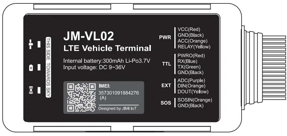
Product overview
Position tracking
GPS & LBS positioning
Real-time location query
Anti-theft
Ignition detection
Power/Fuel cut-off
SOS emergency call
Power supply disconnection alert
Geo-fence alert
Towing alert
Vibration alert
Configurable peripherals
Vehicle door status alert
Turn light/buzzer triggering
Fuel level monitoring
Temperature monitoring
Driver behavior monitoring
Specification
| GSM | B5(850MHz)/B2(1900 MHz) B8(900MHz)/B3(1800MHz) |
| LTE | 81/B2/B3/F34/B5/B12/B13/1328/B66 (JM-VLO2A) B1/B3/85/138/B18/819/820/826 (JM-VLO2E) |
| GNSS Type | MTK all-In-one multi-GNSS SOC |
| Sensitivity | Cold start: <32s Hot start: <1s |
| Position Accuracy (CEP50) | Autonomous: <10m |
| Dimensions | 106mm x 56.8mm x 22mm |
| Weight | 104g |
| Backup Battery | Li-Polymer, 300 mAh |
| Operating Voltage | 9V to 36V DC |
| Operating Temperature | —30°C to +70°C |
| —30°C to +85°C for storage | |
| Transmit Protocol | TCP |
Product setup
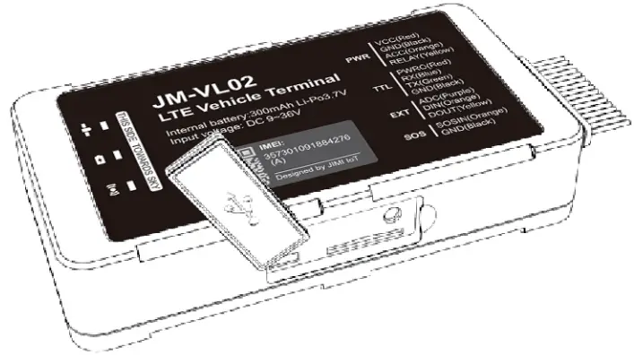
Insert SIM
Remove the soft plug on one side of the device and insert the SIM card into the card slot.
Power on & off
Toggle the power switch beside the SIM slot to power on or off the device.
LED indications
Power Status (Red)
| Behavior | Meaning |
| On for 0.1s and off for 1s | 0%–20% remaining battery |
| On for 0.1s and off for 4s | 20%–100% remaining battery |
| Solid on | Power supply connected |
| GNSS Status (Blue) | |
| Behavior | Meaning |
| On for 0.5s and off for 0.5s | GNSS synchronizing |
| On for 2s and off for 4s | Positioning |
| On for 0.1 s and off for 4s | Positioned |
| Off | GNSS module is in sleep mode or not working |
| Wireless Network & SIM Card Status (Green) | |
| Behavior | Meaning |
| On for 0.5s and off for 0.5s | SIM card not recognized |
| On for 2s and off for 4s | Registered but no inbound acknowledgment |
| On for 0.1s and off for 4s | Network connected |
| Off | No signal received or no SIM card detected |
Interfaces
| PWR | Red | DC 9 to 36v input |
| Black | GND | |
| Yellow | Relay control to cut vehicle fuel support | |
| Orange | Vehicle ignite 12v/24v detection | |
| TTL | Blue | TTL TX |
| Green | TTL RX | |
| Red | DV 5v output max.500mah | |
| Black | GND | |
| EXT | Purple | Analog detect Ov to 30v |
| Orange | GND triggers digital input | |
| Yellow | Extend relay control | |
| SOS | Orange | GND triggers digital input for the SOS function |
| Black | GND |
Wiring indication
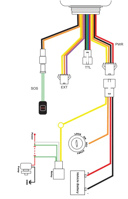
Power connection
The standard power supply ranges from 9V to 36VDC. During installation, the negative side should connect to the ground. Do not connect with other ground wires simultaneously.
Ignition wire
ACC line (orange) connects to the vehicle’s ACC, detecting ignition. Be sure to check if it’s a real ignition wire i.e.power does not disappear after starting the engine.
Relay wiring Relay’s white line (85) connects to the positive side of the battery (12V) while the yellow line (86) connects to the device relay control (yellow line on the power cord).
Find the fuel pump in the vehicle and cut off its positive power line. The positive side of the fuel pump connects to the green line (87a) while the side closing to the starter motor connects to the green line (30) , as the below chart. The switch of the two green lines has the same effect.
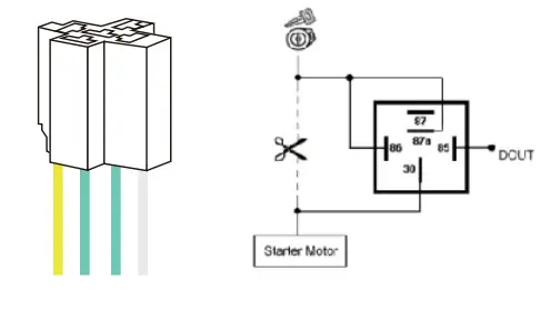 12V relay is standard. The device is suitable for vehicles with a 12V supply. If the vehicle power supply is 24V, use a 24V relay.
Configuration
If you need to change the setting of the device, you can either text the command to the device or use a PC tool from the supplier.
Note: Texting command might be filtered by local carrier network deployment. In this case, you can text through the web management center provided by the carrier.
Common commands
| Command | Description | Remark |
| APN | Set APN | In most countries, APNs could be automatically adapted to local mobile operators. If not, please confirm your APN and do the setting. APN, ApnName# or APN, ApnName, User, Password# Auto set APN will be turned off when set APN manually. APN# Query current APN |
| SERVER | Platform server setting | If you need to use your own server, make sure you have changed the server setting SERVER,1, domain name, port# SERVER, O, IP, portrait Default: SERVER,1, GPSDEV. TRACKSOLID.COM,21102# SERVER# Check the current server settings |
| PARAM | Query device parameters | |
| GPRSSET | Query platform server and APN Setting | |
| STATUS | Query status |
Package & Standard accessories
Standard package…………………………….
JM-VLO2 device……………………………..
Power cable………………………………………
I/O cable………………………………………..
Relay (12V/24V)………………………………
SOS button cable………………………………
Installation recommendation

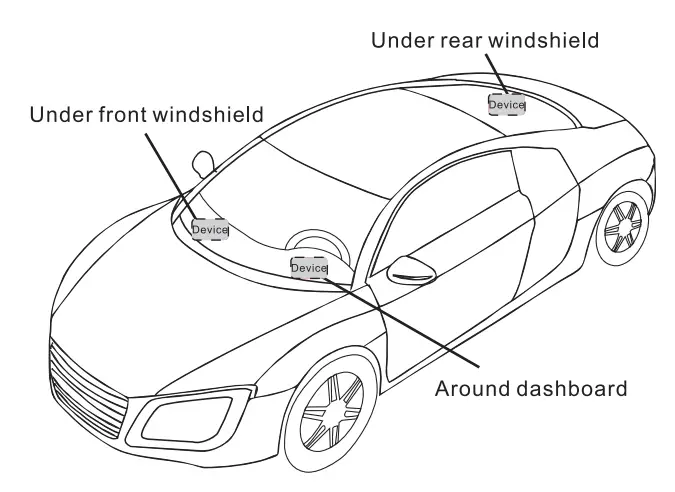
- The device should face up to the sky.
- The metal thermal barrier or heating layer of the windshield affects the signal.
Troubleshooting
| Type | Use |
| Unable to connect to tracking platform | Check the APN and IP settings. Check whether the data service of the SIM card is enabled. Check the balance of the SIM card. |
| Tracker shows offline | Check whether external power is still connected Check if the vehicle entered the network blind area. Check the balance of the SIM card. |
| Unable to locate | Make sure the top side facing upward without metallic things shielded. Make sure it’s not in an area with no satellite coverage. |
| Location drift | In areas with poor GNSS signal (tall buildings around or basement) , drifting may happen. Check whether vibration happens around to trigger the accelerator. |
| No command reply | Make sure the command format is correct. The vehicle may be in-network blind area. Make sure the SIM card is well inserted and has SMS service. |
Warranty instructions
- The warranty is valid only when the warranty card is properly completed and upon presentation of the proof of purchase consisting of the original invoice indicating the date of purchase, model, and serial No.of the product. We reserve the right to refuse a warranty if this information has been removed or changed after the original purchase of the product from the dealer.
- Our obligations are limited to repair of the defect or replacement of the defective part or at its discretion replacement of the product itself.
- Warranty repairs must be carried out by our Authorized Service Centre. Warranty cover will be void, even if a repair has been attempted by any unauthorized service center.
- Repair or replacement under the terms of this warranty does not provide the right to extension or renewal of the warranty period.
- The warranty is not applicable to cases other than defects in material, design, and workmanship.
Maintenance Record
| Date | Service by | ||
| Product Model | |||
| IMEI Number | |||
| FaultDescriptions | |||
| Comments | |||
JM-VLO2
LTE CAT M1 & NB2
VEHICLE TERMINAL
User Manual V1.0


